Service Manual
Page 4
...Dell Shield 39 Replacing the Dell Shield 40 Power Supply 41 Removing the Power Supply 41 Replacing the Power Supply 43 Computer Memory 45 System Memory Installation Guidelines 47 Removing a Memory Module 48 Installing a Memory Module 49 Removing Memory Riser Boards 50 Installing Memory Riser Boards 53 Disk Drives... and Media 55 Installing a CD, Zip, or Other Externally Accessible Drive . . . 57 Installing a Hard Drive 67 EIDE Device Installation Guidelines 74 SCSI Device Installation Guidelines 75 ...
...Dell Shield 39 Replacing the Dell Shield 40 Power Supply 41 Removing the Power Supply 41 Replacing the Power Supply 43 Computer Memory 45 System Memory Installation Guidelines 47 Removing a Memory Module 48 Installing a Memory Module 49 Removing Memory Riser Boards 50 Installing Memory Riser Boards 53 Disk Drives... and Media 55 Installing a CD, Zip, or Other Externally Accessible Drive . . . 57 Installing a Hard Drive 67 EIDE Device Installation Guidelines 74 SCSI Device Installation Guidelines 75 ...
Service Manual
Page 21
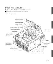
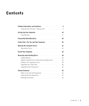
Inside Your Computer The following figure shows the computer with the cover open. NOTE: User service access points are color-coded green. Inside the Computer interior service label diskette drive bracket hard-drive bracket externally accessible-drive bracket chassis intrusion switch control panel memory riser board retention bracket (if needed) microprocessor airflow shroud I/O panel connectors expansion-card slots AGP card brace speaker expansion-card cooling fan system board power supply AC power receptacle power supply airflow vents 21
Inside Your Computer The following figure shows the computer with the cover open. NOTE: User service access points are color-coded green. Inside the Computer interior service label diskette drive bracket hard-drive bracket externally accessible-drive bracket chassis intrusion switch control panel memory riser board retention bracket (if needed) microprocessor airflow shroud I/O panel connectors expansion-card slots AGP card brace speaker expansion-card cooling fan system board power supply AC power receptacle power supply airflow vents 21

Service Manual
Page 55
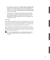
... three 1-inch-high drives, two 1-inch-high drives and one 3.5-inch hard drive. • Hard drive bay: holds up to three 3.5-inch hard drives. See the following drive bays: • One 3.5-inch diskette drive. • Externally accessible drive bay: holds up to three 5.25-inch externally accessible drives or up to two 5.25-inch externally accessible drives and one 1.6-inchhigh drive, or two 1.6-inch...
... three 1-inch-high drives, two 1-inch-high drives and one 3.5-inch hard drive. • Hard drive bay: holds up to three 3.5-inch hard drives. See the following drive bays: • One 3.5-inch diskette drive. • Externally accessible drive bay: holds up to three 5.25-inch externally accessible drives or up to two 5.25-inch externally accessible drives and one 1.6-inchhigh drive, or two 1.6-inch...

Service Manual
Page 57
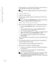
...System Board Components." 1 Turn off . a Squeeze together the tabs at each side of the drive you perform this procedure, see the following figures). 57 If you are installing a new drive, go to step 5. 3 Disconnect the DC power cable and interface cable from their electrical outlets.... To locate this procedure. CAUTION: Before you are replacing. 4 Remove the drive from the chassis (see "Safety First- Installing a CD, Zip, or Other Externally Accessible Drive NOTE: If you are replacing a hard drive that is already installed in the computer, continue with step 3. b Slide the...
...System Board Components." 1 Turn off . a Squeeze together the tabs at each side of the drive you perform this procedure, see the following figures). 57 If you are installing a new drive, go to step 5. 3 Disconnect the DC power cable and interface cable from their electrical outlets.... To locate this procedure. CAUTION: Before you are replacing. 4 Remove the drive from the chassis (see "Safety First- Installing a CD, Zip, or Other Externally Accessible Drive NOTE: If you are replacing a hard drive that is already installed in the computer, continue with step 3. b Slide the...

Service Manual
Page 63
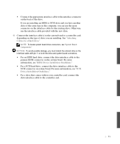
... on the system board. Otherwise, use the spare connector on system board. NOTE: To locate system board drive connectors, see "EIDE Device Installation Guidelines." • For an EIDE hard drive, connect the drive interface cable to the secondary EIDE connector on the back of the same type in the... drive bay cable clips. If you must match the colored strip on the interface cable with pin 1 on the ...
... on the system board. Otherwise, use the spare connector on system board. NOTE: To locate system board drive connectors, see "EIDE Device Installation Guidelines." • For an EIDE hard drive, connect the drive interface cable to the secondary EIDE connector on the back of the same type in the... drive bay cable clips. If you must match the colored strip on the interface cable with pin 1 on the ...
Service Manual
Page 66
...; For other types of the front panel. After you install a tape drive, refer to the documentation that it is operating properly. • If the drive you installed a hard drive, update the drive settings under Secondary Drives to Auto. • If you installed is a hard drive, run the Dell Diagnostics to their own operating software and documentation. See the operating...
...; For other types of the front panel. After you install a tape drive, refer to the documentation that it is operating properly. • If the drive you installed a hard drive, update the drive settings under Secondary Drives to Auto. • If you installed is a hard drive, run the Dell Diagnostics to their own operating software and documentation. See the operating...

Service Manual
Page 67
...disconnecting a device from the computer, wait 10 to disengage the drive bracket from the chassis. CAUTION: Before you perform this light, see "Safety First- a Squeeze together the tabs at each side of the drive you are replacing a hard drive that the standby power light on its electrical outlet. b ...Slide the drive bracket upward, and remove it from their electrical outlets, and wait 10 to back up your...
...disconnecting a device from the computer, wait 10 to disengage the drive bracket from the chassis. CAUTION: Before you perform this light, see "Safety First- a Squeeze together the tabs at each side of the drive you are replacing a hard drive that the standby power light on its electrical outlet. b ...Slide the drive bracket upward, and remove it from their electrical outlets, and wait 10 to back up your...

Service Manual
Page 68
... touching an unpainted metal surface on the back of the computer. See the documentation that accompanied the drive to verify that the drive is configured for your computer. www.dell.com | support.dell.com Removing a Hard Drive 5 Unpack the replacement drive and prepare it for installation. NOTICE: Ground yourself by removing the four screws that secure the...
... touching an unpainted metal surface on the back of the computer. See the documentation that accompanied the drive to verify that the drive is configured for your computer. www.dell.com | support.dell.com Removing a Hard Drive 5 Unpack the replacement drive and prepare it for installation. NOTICE: Ground yourself by removing the four screws that secure the...

Service Manual
Page 69
NOTE: If you are not replacing an existing drive and the new drive does not have bracket rails attached, install the extra rail set that is located inside your computer in an empty drive bay. Attaching Bracket Rails for a Hard Drive drive bracket rails (2) shoulder screws (4) 7 Slide the drive/bracket assembly into the drive bay until both drive bracket tabs snap securely into place (see the following figure). 69 NOTE: You must use the shoulder screws shipped with the spare drive rails.
NOTE: If you are not replacing an existing drive and the new drive does not have bracket rails attached, install the extra rail set that is located inside your computer in an empty drive bay. Attaching Bracket Rails for a Hard Drive drive bracket rails (2) shoulder screws (4) 7 Slide the drive/bracket assembly into the drive bay until both drive bracket tabs snap securely into place (see the following figure). 69 NOTE: You must use the shoulder screws shipped with the spare drive rails.

Service Manual
Page 70
Change any settings necessary for your computer. See the documentation that accompanied the drive and controller card to verify that has its own controller card, install the controller card in an expansion slot. www.dell.com | support.dell.com Installing a Hard Drive 8 If you are installing a drive that the configuration is correct for correct configuration. 9 Connect the cables to the drive. See "Attaching Cables for a Hard Drive." • Connect a DC power cable to the power input connector on the back of the drive. 70
Change any settings necessary for your computer. See the documentation that accompanied the drive and controller card to verify that has its own controller card, install the controller card in an expansion slot. www.dell.com | support.dell.com Installing a Hard Drive 8 If you are installing a drive that the configuration is correct for correct configuration. 9 Connect the cables to the drive. See "Attaching Cables for a Hard Drive." • Connect a DC power cable to the power input connector on the back of the drive. 70
Service Manual
Page 71
... For a SCSI hard drive, connect the drive interface cable to the SCSI connector on system board. NOTICE: To avoid possible damage, you must match the colored strip on the interface cable with pin 1 on both the drive and system board connectors. • For an EIDE hard drive, connect the drive interface cable to ...the primary EIDE connector on the type of drive you are installing an EIDE or SCSI drive and you have another drive of the same type in the computer,...
... For a SCSI hard drive, connect the drive interface cable to the SCSI connector on system board. NOTICE: To avoid possible damage, you must match the colored strip on the interface cable with pin 1 on both the drive and system board connectors. • For an EIDE hard drive, connect the drive interface cable to ...the primary EIDE connector on the type of drive you are installing an EIDE or SCSI drive and you have another drive of the same type in the computer,...

Service Manual
Page 72
Fold cables out of the way to provide airflow for a Hard Drive drive interface cable DC power cable primary EIDE system board connector LVD SCSI system board connector 11 Ensure that all cables are firmly connected. www.dell.com | support.dell.com Attaching Cables for the fan and cooling vents. 12 If the drive bay was previously empty, remove the corresponding insert from the front panel. 72
Fold cables out of the way to provide airflow for a Hard Drive drive interface cable DC power cable primary EIDE system board connector LVD SCSI system board connector 11 Ensure that all cables are firmly connected. www.dell.com | support.dell.com Attaching Cables for the fan and cooling vents. 12 If the drive bay was previously empty, remove the corresponding insert from the front panel. 72

Service Manual
Page 73
.... 15 Reconnect the computer and devices to test the drive. 19 If the hard drive you installed is the primary drive, install the operating system on . See the operating system's documentation for instructions. 18 Run the Dell Diagnostics to their electrical outlets, and turn them on the drive. NOTE: If you update the system settings, exit...
.... 15 Reconnect the computer and devices to test the drive. 19 If the hard drive you installed is the primary drive, install the operating system on . See the operating system's documentation for instructions. 18 Run the Dell Diagnostics to their electrical outlets, and turn them on the drive. NOTE: If you update the system settings, exit...
Service Manual
Page 74
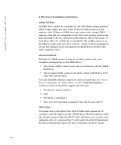
...dell.com | support.dell.com EIDE Device Installation Guidelines Jumper Settings All EIDE drives should be configured for the Cable Select jumper position, which assigns master and slave status to drives by their position on the interface cable. General Guidelines With the two EIDE interface connectors on the system board, your drive...; Ultra ATA/100 (backward-compatible with ATA/66 and ATA/33) EIDE Cables To transfer data at full speed, Ultra ATA/100 hard drives require an 80conductor cable like the ATA/33 cable, but data will operate properly, but it has twice as many wires within the...
...dell.com | support.dell.com EIDE Device Installation Guidelines Jumper Settings All EIDE drives should be configured for the Cable Select jumper position, which assigns master and slave status to drives by their position on the interface cable. General Guidelines With the two EIDE interface connectors on the system board, your drive...; Ultra ATA/100 (backward-compatible with ATA/66 and ATA/33) EIDE Cables To transfer data at full speed, Ultra ATA/100 hard drives require an 80conductor cable like the ATA/33 cable, but data will operate properly, but it has twice as many wires within the...

Service Manual
Page 75
...to 15. NOTICE: Dell recommends that devices be assigned sequentially or that you use one or both of SCSI ID numbers from 0 to 15. NOTE: The system board SCSI controller will have two separate SCSI buses operating. Each SCSI bus will support hard drives only. SCSI Device ...Installation Guidelines This section describes how to work with Dell computers. If you are not guaranteed to configure and install SCSI devices in your computer for ...
...to 15. NOTICE: Dell recommends that devices be assigned sequentially or that you use one or both of SCSI ID numbers from 0 to 15. NOTE: The system board SCSI controller will have two separate SCSI buses operating. Each SCSI bus will support hard drives only. SCSI Device ...Installation Guidelines This section describes how to work with Dell computers. If you are not guaranteed to configure and install SCSI devices in your computer for ...
Service Manual
Page 77
... on the second EIDE channel, such as tape drives, CD drives, and some hard drives) use a 50-pin cable. Refer to partition and format SCSI hard drives. SCSI Cables Ultra 160/m and Ultra2/Wide LVD drives (typically hard drives) both use only SCSI cables purchased from Dell. NOTICE: Dell recommends that came with Dell computers. 77 If you use a 68-pin cable...
... on the second EIDE channel, such as tape drives, CD drives, and some hard drives) use a 50-pin cable. Refer to partition and format SCSI hard drives. SCSI Cables Ultra 160/m and Ultra2/Wide LVD drives (typically hard drives) both use only SCSI cables purchased from Dell. NOTICE: Dell recommends that came with Dell computers. 77 If you use a 68-pin cable...

Service Manual
Page 93
Control Panel Components alignment hole control-panel connector hard-drive access light power button screw hole 93 Control Panel • Components • Removing the control panel • Replacing the control panel Components The following figure shows the control panel and the location of its principal connectors and components.
Control Panel Components alignment hole control-panel connector hard-drive access light power button screw hole 93 Control Panel • Components • Removing the control panel • Replacing the control panel Components The following figure shows the control panel and the location of its principal connectors and components.
Setup and Quick Reference Guide
Page 3
... Dell Precision™ ResourceCD 9 Setting Up Your Computer 10 Dual Monitors 17 Frequently Asked Questions 18 Safety First-For You and Your Computer 20 Opening the Computer Cover 21 Opening the Cover 21 Inside Your Computer 23 Removing and Installing Parts 24 Adding Memory 24 Adding a Hard Drive... or Externally Accessible Drive 24 Adding a PCI Expansion Card 24 Upgrading the Video Card 25 Upgrading Your Processor(s 25 Solving Problems 25 When to...
... Dell Precision™ ResourceCD 9 Setting Up Your Computer 10 Dual Monitors 17 Frequently Asked Questions 18 Safety First-For You and Your Computer 20 Opening the Computer Cover 21 Opening the Cover 21 Inside Your Computer 23 Removing and Installing Parts 24 Adding Memory 24 Adding a Hard Drive... or Externally Accessible Drive 24 Adding a PCI Expansion Card 24 Upgrading the Video Card 25 Upgrading Your Processor(s 25 Solving Problems 25 When to...

Setup and Quick Reference Guide
Page 7
...; Online discussions with other users and technical support • Documentation for components, such as memory, the hard drive, and the operating system • Customer Care - Drivers, patches, and software updates • Reference - Online discussion with other Dell customers • Upgrades - Windows XP Help and Support Center 1 Click the Start button and click Help...
...; Online discussions with other users and technical support • Documentation for components, such as memory, the hard drive, and the operating system • Customer Care - Drivers, patches, and software updates • Reference - Online discussion with other Dell customers • Upgrades - Windows XP Help and Support Center 1 Click the Start button and click Help...
Setup and Quick Reference Guide
Page 18
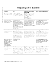
...the user's guide access your Go to the main menu on the Precision ResourceCD? Documentation such as the User's Guide is available on your hard drive. click the User's Guides icon Click User's Guides in the Dell Documents. Make selections on your desktop or click the Topic pull-...down menu and click Dell Precision ResourceCD Guide. Try... Welcome page, click click the User's ...
...the user's guide access your Go to the main menu on the Precision ResourceCD? Documentation such as the User's Guide is available on your hard drive. click the User's Guides icon Click User's Guides in the Dell Documents. Make selections on your desktop or click the Topic pull-...down menu and click Dell Precision ResourceCD Guide. Try... Welcome page, click click the User's ...


