Diagnostics and Troubleshooting Guide (.pdf)
Page 5
...If you use a surge suppressor, line conditioner, or uninterruptible power supply (UPS). • Be sure nothing rests on your ... To help avoid damaging your computer, be sure the voltage selection switch on the power supply is set to match the alternating current (AC) power available at your location: - 115 volts (V)/60 hertz (Hz) in most of... To help ensure proper grounding. If the computer gets wet, see "Troubleshooting a Wet Computer" in electrical power, use your computer system, observe the following safety guidelines to help protect your computer system from potential damage and...
...If you use a surge suppressor, line conditioner, or uninterruptible power supply (UPS). • Be sure nothing rests on your ... To help avoid damaging your computer, be sure the voltage selection switch on the power supply is set to match the alternating current (AC) power available at your location: - 115 volts (V)/60 hertz (Hz) in most of... To help ensure proper grounding. If the computer gets wet, see "Troubleshooting a Wet Computer" in electrical power, use your computer system, observe the following safety guidelines to help protect your computer system from potential damage and...

Diagnostics and Troubleshooting Guide (.pdf)
Page 76
...board problem, follow these steps to step 12. 10. Yes. Go to step 14. 6-8 Diagnostics and Troubleshooting Guide Remove the Dell Diagnostics Diskette from AC power, and remove the computer cover. 8. Turn off the system, disconnect it from drive A , turn it from the computer. 2....video expansion card, and repeat steps 11 and 12. Do the tests complete successfully? Remove all the AC power cables from a defective system board component, a faulty power supply, or a defective component connected to step 13. Enter the System Setup program, and update the system configuration...
...board problem, follow these steps to step 12. 10. Yes. Go to step 14. 6-8 Diagnostics and Troubleshooting Guide Remove the Dell Diagnostics Diskette from AC power, and remove the computer cover. 8. Turn off the system, disconnect it from drive A , turn it from the computer. 2....video expansion card, and repeat steps 11 and 12. Do the tests complete successfully? Remove all the AC power cables from a defective system board component, a faulty power supply, or a defective component connected to step 13. Enter the System Setup program, and update the system configuration...
Diagnostics and Troubleshooting Guide (.pdf)
Page 77
...8226; A diskette drive may be improperly configured. • The diskette drive or tape drive is faulty. • The computer's power supply is correct for the diskette/tape drive subsystem are divided into the following conditions: • The system configuration settings do not match the...Internal Tape Drive" • "Troubleshooting a SCSI Tape Drive" Before you begin the troubleshooting procedures, complete steps 1 and 2 in the Dell Diagnostics to remove it. If the system configuration settings are faulty. • An expansion card is interfering with one drive can affect the...
...8226; A diskette drive may be improperly configured. • The diskette drive or tape drive is faulty. • The computer's power supply is correct for the diskette/tape drive subsystem are divided into the following conditions: • The system configuration settings do not match the...Internal Tape Drive" • "Troubleshooting a SCSI Tape Drive" Before you begin the troubleshooting procedures, complete steps 1 and 2 in the Dell Diagnostics to remove it. If the system configuration settings are faulty. • An expansion card is interfering with one drive can affect the...

Diagnostics and Troubleshooting Guide (.pdf)
Page 83
... drive and reinstall the hard-disk drive. 11. Yes. Go to the drive. Verify that any telephone or telecommunication lines to AC power, reconnect any required SCSI device drivers are required and how they should be installed and configured. Go to step 14. 14. Replace ... drive or controller card, see the SCSI Device Driver Installation and Configuration Guide to your system documentation for the drive spinning up after the power supply turns on obtaining technical assistance. Check the hard-disk drive's jumpers and the controller card's jumpers (if a controller card is using the...
... drive and reinstall the hard-disk drive. 11. Yes. Go to the drive. Verify that any telephone or telecommunication lines to AC power, reconnect any required SCSI device drivers are required and how they should be installed and configured. Go to step 14. 14. Replace ... drive or controller card, see the SCSI Device Driver Installation and Configuration Guide to your system documentation for the drive spinning up after the power supply turns on obtaining technical assistance. Check the hard-disk drive's jumpers and the controller card's jumpers (if a controller card is using the...
Diagnostics and Troubleshooting Guide (.pdf)
Page 126
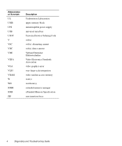
Abbreviation or Acronym UL UMB UPS USB USOC V VAC VDC VDE VESA VGA VLSI VRAM W WH XMM XMS ZIF Description Underwriters Laboratories upper memory block uninterruptible power supply universal serial bus Universal Service Ordering Code volt(s) volt(s) alternating current volt(s) direct current Verband Deutscher Elektrotechniker Video Electronics Standards Association video graphics array very-large-scale integration video random-access memory watt(s) watt-hour(s) extended memory manager eXtended Memory Specification zero insertion force 4 Diagnostics and Troubleshooting Guide
Abbreviation or Acronym UL UMB UPS USB USOC V VAC VDC VDE VESA VGA VLSI VRAM W WH XMM XMS ZIF Description Underwriters Laboratories upper memory block uninterruptible power supply universal serial bus Universal Service Ordering Code volt(s) volt(s) alternating current volt(s) direct current Verband Deutscher Elektrotechniker Video Electronics Standards Association video graphics array very-large-scale integration video random-access memory watt(s) watt-hour(s) extended memory manager eXtended Memory Specification zero insertion force 4 Diagnostics and Troubleshooting Guide
User's Guide (.pdf)
Page 5
... comfort and efficiency, observe the following safety guidelines to help protect your computer system from Dell and other sources) to ensure your own personal safety. Special shelves are equipped with the AC power available in your location. • To help avoid possible damage to the system board... disconnecting a peripheral device from the computer. • To help avoid damaging your computer, be sure the voltage selection switch on the power supply is set to help you use your computer system, observe the following safety guidelines: • To help prevent electric shock, plug the...
... comfort and efficiency, observe the following safety guidelines to help protect your computer system from Dell and other sources) to ensure your own personal safety. Special shelves are equipped with the AC power available in your location. • To help avoid possible damage to the system board... disconnecting a peripheral device from the computer. • To help avoid damaging your computer, be sure the voltage selection switch on the power supply is set to help you use your computer system, observe the following safety guidelines: • To help prevent electric shock, plug the...

User's Guide (.pdf)
Page 16
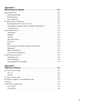
...Connecting to a Network 5-2 Network Cable Requirements 5-2 Configuring the NIC 5-2 Windows NT 4.0 NIC Driver 5-2 Windows 95 NIC Driver 5-3 Dell-Installed Windows 95 Service Release 2 5-3 Windows 95 Operating Systems Not Installed by Dell 5-4 Using the NDIS 2.01 Driver With Windows 95 5-5 Chapter 6 Using the Integrated Audio Controller 6-1 Connecting Audio Devices 6-1 Speakers ... Your Computer 7-3 Removing and Replacing the Expansion-Card Cage 7-4 Removing the Expansion-Card Cage 7-4 Replacing the Expansion-Card Cage 7-5 Rotating the Power Supply Away From the System Board 7-5 xvi
...Connecting to a Network 5-2 Network Cable Requirements 5-2 Configuring the NIC 5-2 Windows NT 4.0 NIC Driver 5-2 Windows 95 NIC Driver 5-3 Dell-Installed Windows 95 Service Release 2 5-3 Windows 95 Operating Systems Not Installed by Dell 5-4 Using the NDIS 2.01 Driver With Windows 95 5-5 Chapter 6 Using the Integrated Audio Controller 6-1 Connecting Audio Devices 6-1 Speakers ... Your Computer 7-3 Removing and Replacing the Expansion-Card Cage 7-4 Removing the Expansion-Card Cage 7-4 Replacing the Expansion-Card Cage 7-5 Rotating the Power Supply Away From the System Board 7-5 xvi
User's Guide (.pdf)
Page 19
... D-2 Cleaning Drives D-3 Environmental Factors D-3 Temperature D-3 Humidity D-3 Altitude D-4 Dust and Particles D-4 Corrosion D-4 ESD D-4 Electromagnetic and Radio Frequency Interference D-4 Magnetism D-5 Shock and Vibration D-5 Power Source Interruptions D-5 Power Protection Devices D-6 Surge Protectors D-6 Line Conditioners D-6 Uninterruptible Power Supply D-6 Appendix E Regulatory Notices E-1 FCC Notices (U.S. Only E-1 Class A E-1 Class B E-2 IC Notice (Canada Only E-2 EN 55022 Compliance (Czech Republic Only E-3 CE Notice...
... D-2 Cleaning Drives D-3 Environmental Factors D-3 Temperature D-3 Humidity D-3 Altitude D-4 Dust and Particles D-4 Corrosion D-4 ESD D-4 Electromagnetic and Radio Frequency Interference D-4 Magnetism D-5 Shock and Vibration D-5 Power Source Interruptions D-5 Power Protection Devices D-6 Surge Protectors D-6 Line Conditioners D-6 Uninterruptible Power Supply D-6 Appendix E Regulatory Notices E-1 FCC Notices (U.S. Only E-1 Class A E-1 Class B E-2 IC Notice (Canada Only E-2 EN 55022 Compliance (Czech Republic Only E-3 CE Notice...

User's Guide (.pdf)
Page 21
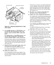
... 7-2 Replacing the Computer Cover 7-3 Computer Orientation View 7-3 Inside the Chassis 7-4 Removing the Expansion-Card Cage 7-5 Rotating the Power Supply 7-5 System Board Features 8-1 Expansion Cards 8-2 Riser-Board Expansion-Card Connectors 8-2 Removing the Filler Bracket 8-3 Installing an Expansion ...Cartridge/Heat Sink Assembly Removal 8-7 System Battery and Battery Socket 8-9 Drive Locations 9-1 Removing a Front-Panel Insert 9-2 DC Power Cable Connector 9-2 Drive Interface Connectors 9-3 Attaching Diskette Drive or Tape Drive Cables 9-5 Installing a Drive on the 3.5-Inch ...
... 7-2 Replacing the Computer Cover 7-3 Computer Orientation View 7-3 Inside the Chassis 7-4 Removing the Expansion-Card Cage 7-5 Rotating the Power Supply 7-5 System Board Features 8-1 Expansion Cards 8-2 Riser-Board Expansion-Card Connectors 8-2 Removing the Filler Bracket 8-3 Installing an Expansion ...Cartridge/Heat Sink Assembly Removal 8-7 System Battery and Battery Socket 8-9 Drive Locations 9-1 Removing a Front-Panel Insert 9-2 DC Power Cable Connector 9-2 Drive Interface Connectors 9-3 Attaching Diskette Drive or Tape Drive Cables 9-5 Installing a Drive on the 3.5-Inch ...
User's Guide (.pdf)
Page 27
...operates as a mouse and printer, to the switch. Rebooting the system in the following indicators and controls (see "Dell AutoShutdown Service" in Chapter 2.) NOTE: A Display Power Management Signaling (DPMS) monitor does not begin warming up when a hard-disk drive is turned on, pressing the button...on system components. Front Panel Your computer's front panel contains the following subsections. To completely remove all power from the system, unplug the AC power cable from the power supply to the input/output (I /O port or connector to which it is attached is turned off the ...
...operates as a mouse and printer, to the switch. Rebooting the system in the following indicators and controls (see "Dell AutoShutdown Service" in Chapter 2.) NOTE: A Display Power Management Signaling (DPMS) monitor does not begin warming up when a hard-disk drive is turned on, pressing the button...on system components. Front Panel Your computer's front panel contains the following subsections. To completely remove all power from the system, unplug the AC power cable from the power supply to the input/output (I /O port or connector to which it is attached is turned off the ...
User's Guide (.pdf)
Page 69
... the following precautions. Touch an unpainted metal surface on your computer. In addition, Dell recommends that you install a hardware option inside the computer. and it shows how to rotate the power supply to gain access to install options inside your computer and all peripherals. 2. If ...the internal components you may handle if you have adequate lighting and a clean work on the computer chassis, such as the power supply, before disconnecting the peripheral or removing the component to avoid possible damage to remove and replace the computer cover and expansion-card ...
... the following precautions. Touch an unpainted metal surface on your computer. In addition, Dell recommends that you install a hardware option inside the computer. and it shows how to rotate the power supply to gain access to install options inside your computer and all peripherals. 2. If ...the internal components you may handle if you have adequate lighting and a clean work on the computer chassis, such as the power supply, before disconnecting the peripheral or removing the component to avoid possible damage to remove and replace the computer cover and expansion-card ...
User's Guide (.pdf)
Page 71
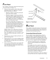
back of computer expansion card cage left side power supply hard-disk drive bracket drive cage right side hooks...install the option. Some hardware options are ready to secure your computer, note the direct current (DC) power cables coming from electrostatic damage. Pivot the cover down toward the back and into position (make sure the... peripherals. Replacing the Computer Cover 4. Unpacking Your Hardware Option When you may find it from the power supply. These cables supply power to change a jumper setting on the system board, and/or a jumper or switch setting on ...
back of computer expansion card cage left side power supply hard-disk drive bracket drive cage right side hooks...install the option. Some hardware options are ready to secure your computer, note the direct current (DC) power cables coming from electrostatic damage. Pivot the cover down toward the back and into position (make sure the... peripherals. Replacing the Computer Cover 4. Unpacking Your Hardware Option When you may find it from the power supply. These cables supply power to change a jumper setting on the system board, and/or a jumper or switch setting on ...

User's Guide (.pdf)
Page 72
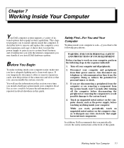
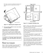
...through the back-panel openings. DC power cable diskette/tape drive interface cable power supply AC power receptacle voltage selection switch drive in jack line-out jack expansion-card cage system board video connector Removing and Replacing the Expansion-Card Cage Your Dell computer has a removable expansion-card ... Expansion-Card Cage Use the following procedure to where the cage must be placed while removed from the chassis. 7-4 Dell Workstation Midsize Systems User's Guide Remove the computer cover as instructed in "Removing the Computer Cover" found earlier in this chapter. 2.
...through the back-panel openings. DC power cable diskette/tape drive interface cable power supply AC power receptacle voltage selection switch drive in jack line-out jack expansion-card cage system board video connector Removing and Replacing the Expansion-Card Cage Your Dell computer has a removable expansion-card ... Expansion-Card Cage Use the following procedure to where the cage must be placed while removed from the chassis. 7-4 Dell Workstation Midsize Systems User's Guide Remove the computer cover as instructed in "Removing the Computer Cover" found earlier in this chapter. 2.
User's Guide (.pdf)
Page 73
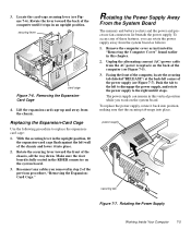
...lever toward the back of the computer (see Figure 7-5). 3. Rotating the Power Supply Away From the System Board The memory and battery sockets and the power and processor fan connectors lie beneath the power supply. power supply securing tab Figure 7-7. 3. With the securing lever in an upright position... Facing the front of the computer, locate the securing tab (labeled "RELEASE") at the back-left to disengage the power supply, and rotate the power supply to replace the expansioncard cage: 1. Remove the computer cover as follows: 1. To access any cables you removed in the...
...lever toward the back of the computer (see Figure 7-5). 3. Rotating the Power Supply Away From the System Board The memory and battery sockets and the power and processor fan connectors lie beneath the power supply. power supply securing tab Figure 7-7. 3. With the securing lever in an upright position... Facing the front of the computer, locate the securing tab (labeled "RELEASE") at the back-left to disengage the power supply, and rotate the power supply to replace the expansioncard cage: 1. Remove the computer cover as follows: 1. To access any cables you removed in the...

User's Guide (.pdf)
Page 79
... are operating properly. To do so, follow the instructions in Chapter 7. 3. Determine the DIMM sockets into place. 6. Run the Dell Diagnostics to verify that may occur. See your Diagnostics and Troubleshooting Guide for information on . To access the DIMM sockets on self-...section. 5. CAUTION: See "Protecting Against Electrostatic Discharge" in the socket you want to exit the System Setup program. 9. Rotate the power supply back into position, making sure the securing tab snaps into which you will install DIMMs or replace existing DIMMs. 4. Replace the computer cover...
... are operating properly. To do so, follow the instructions in Chapter 7. 3. Determine the DIMM sockets into place. 6. Run the Dell Diagnostics to verify that may occur. See your Diagnostics and Troubleshooting Guide for information on . To access the DIMM sockets on self-...section. 5. CAUTION: See "Protecting Against Electrostatic Discharge" in the socket you want to exit the System Setup program. 9. Rotate the power supply back into position, making sure the securing tab snaps into which you will install DIMMs or replace existing DIMMs. 4. Replace the computer cover...
User's Guide (.pdf)
Page 80
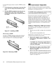
... of the socket. Removing a DIMM Microprocessor Upgrades To take advantage of tabs on the system board. Rotate the power supply as the first processor. Remove the airflow shroud from the socket (see Figure 8-9). 8-6 Dell Workstation Midsize Systems User's Guide Squeeze both pairs of future options in speed and functionality, you can add a second...
... of the socket. Removing a DIMM Microprocessor Upgrades To take advantage of tabs on the system board. Rotate the power supply as the first processor. Remove the airflow shroud from the socket (see Figure 8-9). 8-6 Dell Workstation Midsize Systems User's Guide Squeeze both pairs of future options in speed and functionality, you can add a second...
User's Guide (.pdf)
Page 82
...new SEC cartridge/heat sink assembly into the alignment slot on the left side of the fan and between the fan and the power supply bracket on running Windows NT 4.0, reinstall the operating system. Install or replace the two large thumbscrews that the securing tab snaps... into position. Enter the System Setup program. however, without a battery; In 8-8 Dell Workstation Midsize Systems User's Guide Rotate the power supply back into place. Replace the airflow shroud over the processor(s). The processor speed jumper should be set - As the...
...new SEC cartridge/heat sink assembly into the alignment slot on the left side of the fan and between the fan and the power supply bracket on running Windows NT 4.0, reinstall the operating system. Install or replace the two large thumbscrews that the securing tab snaps... into position. Enter the System Setup program. however, without a battery; In 8-8 Dell Workstation Midsize Systems User's Guide Rotate the power supply back into place. Replace the airflow shroud over the processor(s). The processor speed jumper should be set - As the...

User's Guide (.pdf)
Page 83
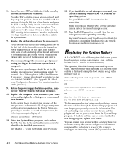
...system battery with the side labeled "+" facing up. Replace the battery only with the object. System Battery and Battery Socket 5. Rotate the power supply back into position, making sure that the object is inserted between the battery and the socket before attempting to your fingers or with a ...on the system board. Otherwise, you have not already done so, make a copy of the system board (as described in "Rotating the Power Supply Away From the System Board" in Chapter 7. Pry the battery out of the system). Discard used batteries according to the instructions in "...
...system battery with the side labeled "+" facing up. Replace the battery only with the object. System Battery and Battery Socket 5. Rotate the power supply back into position, making sure that the object is inserted between the battery and the socket before attempting to your fingers or with a ...on the system board. Otherwise, you have not already done so, make a copy of the system board (as described in "Rotating the Power Supply Away From the System Board" in Chapter 7. Pry the battery out of the system). Discard used batteries according to the instructions in "...
User's Guide (.pdf)
Page 88
... tape drive interface cable, check the documentation for connecting the new EIDE drive. Otherwise, use . If you want to rotate the power supply out of Cable Select, see Figure 9-5). Change any jumper and switch settings necessary for your computer system. CAUTION: See "Protecting Against ...Electrostatic Discharge" in the drive kit. Attach the bracket to your system. 9-4 Dell Workstation Midsize Systems User's Guide and check the documentation that accompanied the drive to verify that the drive is configured for your configuration.
... tape drive interface cable, check the documentation for connecting the new EIDE drive. Otherwise, use . If you want to rotate the power supply out of Cable Select, see Figure 9-5). Change any jumper and switch settings necessary for your computer system. CAUTION: See "Protecting Against ...Electrostatic Discharge" in the drive kit. Attach the bracket to your system. 9-4 Dell Workstation Midsize Systems User's Guide and check the documentation that accompanied the drive to verify that the drive is configured for your configuration.
User's Guide (.pdf)
Page 89
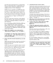
... . 12. For a diskette drive, enter the System Setup program and update the appropriate Diskette Drive category (A or B) on Page 1 of the Dell Diagnostics. If you installed a non-EIDE tape drive as instructed in the order marked. Check all the subtests in step 7, the cable may occur.... If you install a tape drive, refer to the documentation that came with the drive for easier access inside the chassis, rotate the power supply back into position, making sure to their own operating software and documentation. Replace the drive in this chapter. 10. Then perform a tape...
... . 12. For a diskette drive, enter the System Setup program and update the appropriate Diskette Drive category (A or B) on Page 1 of the Dell Diagnostics. If you installed a non-EIDE tape drive as instructed in the order marked. Check all the subtests in step 7, the cable may occur.... If you install a tape drive, refer to the documentation that came with the drive for easier access inside the chassis, rotate the power supply back into position, making sure to their own operating software and documentation. Replace the drive in this chapter. 10. Then perform a tape...


