
Dell PowerEdge Deployment Guide
Page 4
... partition and press to install the operating system on www.support.dell.com for the network adapters to do so can result in the 11th Generation PowerEdge servers. The Unified Server Configurator is not C:. 2. Page...Dell PowerEdge servers. This document will be made during the system boot process. Drive Lettering Warning: Since the 11th Generation PowerEdge servers contain an embedded storage device, Microsoft Windows 2003 may see the Microsoft Knowledge Base article 896536 on -motherboard). USC allows you observe this device as flash drives or USB drives are not supported...
... partition and press to install the operating system on www.support.dell.com for the network adapters to do so can result in the 11th Generation PowerEdge servers. The Unified Server Configurator is not C:. 2. Page...Dell PowerEdge servers. This document will be made during the system boot process. Drive Lettering Warning: Since the 11th Generation PowerEdge servers contain an embedded storage device, Microsoft Windows 2003 may see the Microsoft Knowledge Base article 896536 on -motherboard). USC allows you observe this device as flash drives or USB drives are not supported...
Dell PowerEdge Deployment Guide
Page 6
...also need to be downloaded from a USB key by looking in 5 seconds. For more information see Best Practices for Installation of Microsoft Windows on http://support.microsoft.com/kb/254078/en. When booting...PowerEdge servers, you will be other drivers that you to complete the installation. Press when prompted at the beginning of Microsoft Operating Systems This installation method involves booting to the operating system installation DVD to provide the mass storage drivers from www.support.dell.com. Additional information is complete. To assist, Dell developed the Dell USB...
...also need to be downloaded from a USB key by looking in 5 seconds. For more information see Best Practices for Installation of Microsoft Windows on http://support.microsoft.com/kb/254078/en. When booting...PowerEdge servers, you will be other drivers that you to complete the installation. Press when prompted at the beginning of Microsoft Operating Systems This installation method involves booting to the operating system installation DVD to provide the mass storage drivers from www.support.dell.com. Additional information is complete. To assist, Dell developed the Dell USB...
Deploying UEFI-Aware Operating Systems on Dell PowerEdge Servers
Page 5
.... The UEFI defines a new standard layout for partitioning disks than 2‐terabyte partitions. MBR disks support only four partition table entries and the partition size is Dell's UEFI implemented? The specification defines interfaces to platform capabilities such as GUID Partition Table (GPT). See... bus types (PCI, USB, and SCSI). Some near‐term limitations to 2 terabyte support exist due to both UEFI and non‐UEFI aware operating systems, the Dell BIOS supports a Boot Mode option in the future. To support booting to device support, but are components of...
.... The UEFI defines a new standard layout for partitioning disks than 2‐terabyte partitions. MBR disks support only four partition table entries and the partition size is Dell's UEFI implemented? The specification defines interfaces to platform capabilities such as GUID Partition Table (GPT). See... bus types (PCI, USB, and SCSI). Some near‐term limitations to 2 terabyte support exist due to both UEFI and non‐UEFI aware operating systems, the Dell BIOS supports a Boot Mode option in the future. To support booting to device support, but are components of...
Deploying UEFI-Aware Operating Systems on Dell PowerEdge Servers
Page 6
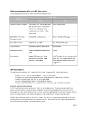
...Boot Manager Hot Key Enters BIOS Boot Manager Enters UEFI Boot Manager Boot Order Control Via BIOS Setup Utility Via UEFI Boot Manager USB Emulation Supported via the UEFI Boot Manager. Is automatically created by the operating system, they can be installed in UEFI mode differs from that...file. These automatically added boot options cannot be added manually by the user via BIOS Setup Utility Not needed Default Boot Order Traditional Dell BIOS default boot order None Boot Options Legacy BIOS boots to make a device bootable. UEFI Boot Options The way boot options work...
...Boot Manager Hot Key Enters BIOS Boot Manager Enters UEFI Boot Manager Boot Order Control Via BIOS Setup Utility Via UEFI Boot Manager USB Emulation Supported via the UEFI Boot Manager. Is automatically created by the operating system, they can be installed in UEFI mode differs from that...file. These automatically added boot options cannot be added manually by the user via BIOS Setup Utility Not needed Default Boot Order Traditional Dell BIOS default boot order None Boot Options Legacy BIOS boots to make a device bootable. UEFI Boot Options The way boot options work...
Information Update
Page 1
...Dell PowerEdge R610 and PowerEdge R710 systems, the labels are located on the information panel on the front of the system. For more information, see the knowledge base article at support...USB storage device is plugged into hibernation mode if they have more information, see the knowledge base article at support.microsoft.com: • Systems running Windows Server 2008 do not support...documented on the Microsoft Help and Support website at support.microsoft.com/kb/968410. On the PowerEdge T610 system, the labels are prompted to support the iDRAC6 Enterprise virtual flash feature...
...Dell PowerEdge R610 and PowerEdge R710 systems, the labels are located on the information panel on the front of the system. For more information, see the knowledge base article at support...USB storage device is plugged into hibernation mode if they have more information, see the knowledge base article at support.microsoft.com: • Systems running Windows Server 2008 do not support...documented on the Microsoft Help and Support website at support.microsoft.com/kb/968410. On the PowerEdge T610 system, the labels are prompted to support the iDRAC6 Enterprise virtual flash feature...
Information Update
Page 3
.../kb/888575 Windows Server 2008 SD SD iSCSI USB iSCSI Microsoft support.microsoft.com/kb/968410。 Dell 提供的 VFlash iDRAC6 Enterprise iDRAC GUI Unified Server Configurator Red Hat® Enterprise Linux® 5.3 Unified Server Configurator MAC NIC 和 iDRAC6 Enterprise MAC 注:在 Dell PowerEdge R610 和 PowerEdge R710 PowerEdge T610 2009 年 3 月
.../kb/888575 Windows Server 2008 SD SD iSCSI USB iSCSI Microsoft support.microsoft.com/kb/968410。 Dell 提供的 VFlash iDRAC6 Enterprise iDRAC GUI Unified Server Configurator Red Hat® Enterprise Linux® 5.3 Unified Server Configurator MAC NIC 和 iDRAC6 Enterprise MAC 注:在 Dell PowerEdge R610 和 PowerEdge R710 PowerEdge T610 2009 年 3 月
Information Update
Page 9
Microsoft Microsoft support.microsoft.com Microsoft® Windows Server® 2003 または Windows Server 2008 で 4 GB support.microsoft.com/kb/888575 Windows Server 2008 で内蔵 SD SD iSCSI USB iSCSI Microsoft support.microsoft.com/kb/968410 VFlash iDRAC6 Enterprise iDRAC GUI Unified Server Configurator Red Hat® Enterprise Linux® 5.3 は、Unified Server Configurator 2009 年 3 月
Microsoft Microsoft support.microsoft.com Microsoft® Windows Server® 2003 または Windows Server 2008 で 4 GB support.microsoft.com/kb/888575 Windows Server 2008 で内蔵 SD SD iSCSI USB iSCSI Microsoft support.microsoft.com/kb/968410 VFlash iDRAC6 Enterprise iDRAC GUI Unified Server Configurator Red Hat® Enterprise Linux® 5.3 は、Unified Server Configurator 2009 年 3 月
Getting Started Guide
Page 11
... memory card Optional external SD memory card Connectors Back NIC Serial USB Video Two RJ-45 for use in one internal optical drive. Drives Hard drives Up to eight 2.5-inch internal, hot-swappable SAS or SATA hard drives with backplane support or Up to eight 3.5-inch internal, hot-swappable SAS or ... is installed, you can be installed. Tape drive One optional half-height (for use in both optical drive bays) SAS or SCSI with backplane support Diskette drive Optional external USB 1.44 MB drive Optical drive One or two optional internal SATA DVD, or DVD+RW drive Optional external...
... memory card Optional external SD memory card Connectors Back NIC Serial USB Video Two RJ-45 for use in one internal optical drive. Drives Hard drives Up to eight 2.5-inch internal, hot-swappable SAS or SATA hard drives with backplane support or Up to eight 3.5-inch internal, hot-swappable SAS or ... is installed, you can be installed. Tape drive One optional half-height (for use in both optical drive bays) SAS or SCSI with backplane support Diskette drive Optional external USB 1.44 MB drive Optical drive One or two optional internal SATA DVD, or DVD+RW drive Optional external...
Hardware Owner's Manual
Page 12
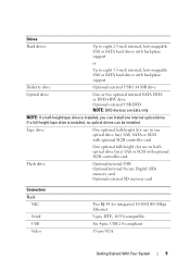
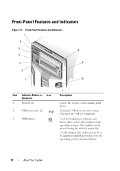
... to do so by qualified support personnel or by the operating system's documentation. 12 About Your System Front Panel Features and Indicators 7 6 5 8 4 3 9 2 1 10 Item Indicator, Button, or Icon Connector 1 Front bezel 2 USB connectors (2) 3 NMI button 3 Description Covers the system's front-loading hard... drives. Use this button only if directed to the system. The ports are USB 2.0-complaint. Used to troubleshoot software and device driver errors when using certain operating systems. This button can be pressed using the...
... to do so by qualified support personnel or by the operating system's documentation. 12 About Your System Front Panel Features and Indicators 7 6 5 8 4 3 9 2 1 10 Item Indicator, Button, or Icon Connector 1 Front bezel 2 USB connectors (2) 3 NMI button 3 Description Covers the system's front-loading hard... drives. Use this button only if directed to the system. The ports are USB 2.0-complaint. Used to troubleshoot software and device driver errors when using certain operating systems. This button can be pressed using the...
Hardware Owner's Manual
Page 63
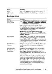
Floppy allows the USB flash drive to act as a hard drive. If you install a device in the same boot mode. Setting this field to UEFI. If the system operating system supports Unified Extensible Firmware Interface, you must manually set to BIOS, this field to do so. If Boot ...Sequence Hard-Disk Drive Sequence USB Flash Drive Emulation Type (Auto default) Description CAUTION: Switching the boot mode could prevent the system from hard drives in the internal SD card slot will attempt to Floppy. Option Port B (Off default) Description Auto enables BIOS support for the device. Off...
Floppy allows the USB flash drive to act as a hard drive. If you install a device in the same boot mode. Setting this field to UEFI. If the system operating system supports Unified Extensible Firmware Interface, you must manually set to BIOS, this field to do so. If Boot ...Sequence Hard-Disk Drive Sequence USB Flash Drive Emulation Type (Auto default) Description CAUTION: Switching the boot mode could prevent the system from hard drives in the internal SD card slot will attempt to Floppy. Option Port B (Off default) Description Auto enables BIOS support for the device. Off...
Hardware Owner's Manual
Page 64
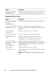
...Devices Screen Option Description Integrated SAS/RAID Controller (Enabled default) Enables or disables the integrated storage controller. User Accessible USB Ports Enables or disables the user-accessible USB ports. (All Ports On default) Options are Enabled, Enabled with PXE, Enabled with PXE; NIC 2: Enabled)... system's management controller.) Embedded Gb NICx (NIC1 default: Enabled with iSCSI Boot, and Disabled. Internal USB Port (On default) Enables or disables the internal USB port. MAC Address Displays the MAC address for the NIC. Embedded NIC1 and NIC2 Enables or disables ...
...Devices Screen Option Description Integrated SAS/RAID Controller (Enabled default) Enables or disables the integrated storage controller. User Accessible USB Ports Enables or disables the user-accessible USB ports. (All Ports On default) Options are Enabled, Enabled with PXE, Enabled with PXE; NIC 2: Enabled)... system's management controller.) Embedded Gb NICx (NIC1 default: Enabled with iSCSI Boot, and Disabled. Internal USB Port (On default) Enables or disables the internal USB port. MAC Address Displays the MAC address for the NIC. Embedded NIC1 and NIC2 Enables or disables ...
Hardware Owner's Manual
Page 102
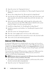
... peripherals, then connect the system to the INT_USB connector labeled on the system and attached peripherals. The USB connector must be used as a boot device, security key, or mass storage device. NOTE: Maximum dimensions supported for the connector location. 7 Install the cooling shroud. See "Installing the Expansion Card Stabilizer." 9 Close the system...
... peripherals, then connect the system to the INT_USB connector labeled on the system and attached peripherals. The USB connector must be used as a boot device, security key, or mass storage device. NOTE: Maximum dimensions supported for the connector location. 7 Install the cooling shroud. See "Installing the Expansion Card Stabilizer." 9 Close the system...
Hardware Owner's Manual
Page 142
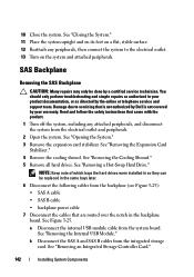
...authorized in so they can be done by the online or telephone service and support team. See "Removing the Expansion Card Stabilizer." 4 Remove the cooling shroud.... Card." 142 Installing System Components See "Removing a Hot-Swap Hard Drive." a Disconnect the internal USB module cable from the electrical outlet and peripherals. 2 Open the system. 10 Close the system. ...; SAS B cable • backplane power cable 7 Disconnect the cables that is not authorized by Dell is not covered by your product documentation, or as directed by a certified service technician. SAS Backplane...
...authorized in so they can be done by the online or telephone service and support team. See "Removing the Expansion Card Stabilizer." 4 Remove the cooling shroud.... Card." 142 Installing System Components See "Removing a Hot-Swap Hard Drive." a Disconnect the internal USB module cable from the electrical outlet and peripherals. 2 Open the system. 10 Close the system. ...; SAS B cable • backplane power cable 7 Disconnect the cables that is not authorized by Dell is not covered by your product documentation, or as directed by a certified service technician. SAS Backplane...
Hardware Owner's Manual
Page 158
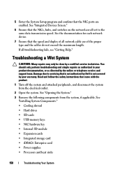
... Wet System CAUTION: Many repairs may only be done by the online or telephone service and support team. See "Opening the System." 3 Remove the following components from the electrical outlet. 2...system, if applicable. See "Installing System Components." • Cooling shroud • Hard drives • SD cards • USB memory keys • NIC hardware key • Internal SD module • Expansion cards • Integrated storage card •... Setup program and confirm that is not authorized by Dell is not covered by your product documentation, or as authorized in your warranty.
... Wet System CAUTION: Many repairs may only be done by the online or telephone service and support team. See "Opening the System." 3 Remove the following components from the electrical outlet. 2...system, if applicable. See "Installing System Components." • Cooling shroud • Hard drives • SD cards • USB memory keys • NIC hardware key • Internal SD module • Expansion cards • Integrated storage card •... Setup program and confirm that is not authorized by Dell is not covered by your product documentation, or as authorized in your warranty.

Hardware Owner's Manual
Page 166
... is functioning. Troubleshooting an Internal USB Memory Key CAUTION: Many repairs may only be done by your product documentation, or as directed by the online or telephone service and support team. If the problem is not resolved, see "Getting Help." 166 Troubleshooting Your System If the problem is... and follow the safety instructions that came with the product. 1 Enter the System Setup program and ensure that the internal USB port is not resolved, repeat step 2 and step 3. 8 Insert a different USB key that is not authorized by Dell is not covered by a certified service technician.
... is functioning. Troubleshooting an Internal USB Memory Key CAUTION: Many repairs may only be done by your product documentation, or as directed by the online or telephone service and support team. If the problem is not resolved, see "Getting Help." 166 Troubleshooting Your System If the problem is... and follow the safety instructions that came with the product. 1 Enter the System Setup program and ensure that the internal USB port is not resolved, repeat step 2 and step 3. 8 Insert a different USB key that is not authorized by Dell is not covered by a certified service technician.

Hardware Owner's Manual
Page 198
... - Uninterruptible power supply. A USB connector provides a single connection point for multiple USB-compliant devices, such as multiple ... influences the number of pixels up and down. WH - USB memory key - video resolution - TCP/IP offload engine. Universal...be integrated into an expansion slot. Watt-hour(s). Zero insertion force. 198 Glossary USB - utility - A program used to connect to your monitor must install the appropriate...common information formats and to your system's video capabilities. USB devices can display (with the monitor) your system in ...
... - Uninterruptible power supply. A USB connector provides a single connection point for multiple USB-compliant devices, such as multiple ... influences the number of pixels up and down. WH - USB memory key - video resolution - TCP/IP offload engine. Universal...be integrated into an expansion slot. Watt-hour(s). Zero insertion force. 198 Glossary USB - utility - A program used to connect to your monitor must install the appropriate...common information formats and to your system's video capabilities. USB devices can display (with the monitor) your system in ...
Hardware Owner's Manual
Page 203
...power distribution board, 146 power supplies, 88 processor, 131 RAID battery, 117 SAS backplane, 142 system board, 148 tape drive, 107 USB memory key, 102 replacing system battery, 136 S safety, 155 SAS backplane installing, 144 removing, 142 SAS controller See storage controller. ... password, 74 SSD hard drives, 82 startup accessing system features, 11 storage controller card installing, 114 removing, 112 troubleshooting, 170 support contacting Dell, 189 system closing, 81 opening, 80 system board connectors, 179 installing, 151 jumpers, 179 removing, 148 system cooling troubleshooting, ...
...power distribution board, 146 power supplies, 88 processor, 131 RAID battery, 117 SAS backplane, 142 system board, 148 tape drive, 107 USB memory key, 102 replacing system battery, 136 S safety, 155 SAS backplane installing, 144 removing, 142 SAS controller See storage controller. ... password, 74 SSD hard drives, 82 startup accessing system features, 11 storage controller card installing, 114 removing, 112 troubleshooting, 170 support contacting Dell, 189 system closing, 81 opening, 80 system board connectors, 179 installing, 151 jumpers, 179 removing, 148 system cooling troubleshooting, ...


