
Tower-to-Rack Conversion Guide
Page 4
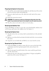
...Figure 1-1. WARNING: The system may weigh up to -Rack Conversion Guide See Figure 1-1. 4 Tower-to 38 kilograms (84 pounds) when fully loaded. Removing the Stabilizer Feet Using a #2 Phillips screwdriver, remove the screws that secure the top chassis panel to the unlocked position. 2 Pull the cover ...cover away from the electrical outlet and peripherals. 2 If present, unlock and remove the cable lock on the back of the system chassis. 3 Rotate the system feet inward. Preparing the System for Conversion 1 Turn off the system and attached peripherals, and disconnect the system...
...Figure 1-1. WARNING: The system may weigh up to -Rack Conversion Guide See Figure 1-1. 4 Tower-to 38 kilograms (84 pounds) when fully loaded. Removing the Stabilizer Feet Using a #2 Phillips screwdriver, remove the screws that secure the top chassis panel to the unlocked position. 2 Pull the cover ...cover away from the electrical outlet and peripherals. 2 If present, unlock and remove the cable lock on the back of the system chassis. 3 Rotate the system feet inward. Preparing the System for Conversion 1 Turn off the system and attached peripherals, and disconnect the system...
Tower-to-Rack Conversion Guide
Page 5
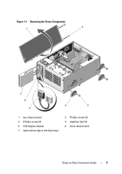
Figure 1-1. Removing the Tower Components 1 2 7 6 5 4 3 1 top chassis panel 3 Phillips screw (4) 5 LCD display module 7 optical drive (top or left drive bay) 2 Phillips screw (2) 4 stabilizer foot (4) 6 drive release latch Tower-to-Rack Conversion Guide 5
Figure 1-1. Removing the Tower Components 1 2 7 6 5 4 3 1 top chassis panel 3 Phillips screw (4) 5 LCD display module 7 optical drive (top or left drive bay) 2 Phillips screw (2) 4 stabilizer foot (4) 6 drive release latch Tower-to-Rack Conversion Guide 5
Tower-to-Rack Conversion Guide
Page 6
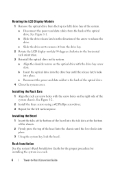
... to release the drive. See Figure 1-2. 2 Install the three screws using a #2 Phillips screwdriver. 3 Repeat for installing the system in a rack. 6 Tower-to the back of the system chassis. Installing the Bezel 1 Insert the tabs at the bottom of the bezel into the tab slots at the bottom of the... chassis. 2 Firmly press the top of the arrow to the horizontal rack orientation. 3 Reinstall the optical drive in the direction of the bezel into the chassis until the release latch locks into place. 3 Using the system key,...
... to release the drive. See Figure 1-2. 2 Install the three screws using a #2 Phillips screwdriver. 3 Repeat for installing the system in a rack. 6 Tower-to the back of the system chassis. Installing the Bezel 1 Insert the tabs at the bottom of the bezel into the tab slots at the bottom of the... chassis. 2 Firmly press the top of the arrow to the horizontal rack orientation. 3 Reinstall the optical drive in the direction of the bezel into the chassis until the release latch locks into place. 3 Using the system key,...
Hardware Owner's Manual
Page 88
... supply out of High Output and Energy Smart power supplies. See "Installing a Power Supply Blank." For information about the cable management arm, see the system's rack documentation. 1 Disconnect the power cable from the power source and the power supply you intend to remove, and remove the cables from a High Output configuration... output. NOTE: You may have to make a matched pair can result in a non-redundant configuration. NOTE: The system does not support a mixed installation of the chassis.
... supply out of High Output and Energy Smart power supplies. See "Installing a Power Supply Blank." For information about the cable management arm, see the system's rack documentation. 1 Disconnect the power cable from the power source and the power supply you intend to remove, and remove the cables from a High Output configuration... output. NOTE: You may have to make a matched pair can result in a non-redundant configuration. NOTE: The system does not support a mixed installation of the chassis.
Hardware Owner's Manual
Page 89
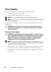
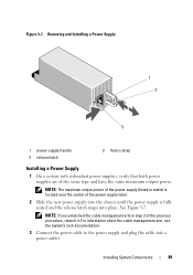
See Figure 3-7. Installing System Components 89 Figure 3-7. For information about the cable management arm, see the system's rack documentation. 3 Connect the power cable to the power supply and plug the cable into place. NOTE: The maximum output power of the power supply (listed ... Supply 1 On a system with redundant power supplies, verify that both power supplies are of the power supply label. 2 Slide the new power supply into the chassis until the power supply is fully seated and the release latch snaps into a power outlet.
See Figure 3-7. Installing System Components 89 Figure 3-7. For information about the cable management arm, see the system's rack documentation. 3 Connect the power cable to the power supply and plug the cable into place. NOTE: The maximum output power of the power supply (listed ... Supply 1 On a system with redundant power supplies, verify that both power supplies are of the power supply label. 2 Slide the new power supply into the chassis until the power supply is fully seated and the release latch snaps into a power outlet.
Hardware Owner's Manual
Page 152
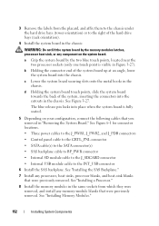
...Backplane." 7 Install any memory-module blanks that you removed in Figure 3-27). c Lower the system board securing slots onto the metal hooks in the chassis. See Figure 6-1 for connector locations. • Three power cables to the J_PWR1, J_PWR2, and J_PDB connectors • Control panel cable to the... connector • Internal USB module cable to the right of the hard drive bays (rack orientation). 4 Install the system board in the same sockets from the placard, and affix them to the chassis under the hard drive bays (tower orientation) or to the INT_USB connector 6 Install the...
...Backplane." 7 Install any memory-module blanks that you removed in Figure 3-27). c Lower the system board securing slots onto the metal hooks in the chassis. See Figure 6-1 for connector locations. • Three power cables to the J_PWR1, J_PWR2, and J_PDB connectors • Control panel cable to the... connector • Internal USB module cable to the right of the hard drive bays (rack orientation). 4 Install the system board in the same sockets from the placard, and affix them to the chassis under the hard drive bays (tower orientation) or to the INT_USB connector 6 Install the...


