

Glossary
Page 1
... not boot from SNMP agents. A CD, diskette, or USB memory key that is located. Your system contains an expansion bus that includes power supplies and fans. C - Alternating current. ANSI - blade - A - BMC - bus - ambient temperature - backup - American National Standards... authority. CIM - ACPI - An individual code assigned to the system. Celsius. bootable media - asset tag - Centimeter(s). 1 Dell™ Glossary NOTE: For additional information on storage terminology, visit the Storage Networking Industry Association's website at www.snia.org and ...
... not boot from SNMP agents. A CD, diskette, or USB memory key that is located. Your system contains an expansion bus that includes power supplies and fans. C - Alternating current. ANSI - blade - A - BMC - bus - ambient temperature - backup - American National Standards... authority. CIM - ACPI - An individual code assigned to the system. Celsius. bootable media - asset tag - Centimeter(s). 1 Dell™ Glossary NOTE: For additional information on storage terminology, visit the Storage Networking Industry Association's website at www.snia.org and ...

Glossary
Page 8
... in the cable. The amount of your system in an array. system board - Data stored in memory that automatically supplies power to I/O devices. Transmission Control Protocol/Internet Protocol. termination - A port on each disk used to connect to enable ...with greater resolution and color display capabilities than previous standards. striping - system configuration information - Uninterruptible power supply. Universal Serial Bus. uplink port - A battery-powered unit that tells a system what hardware is installed and how the system should be connected and disconnected...
... in the cable. The amount of your system in an array. system board - Data stored in memory that automatically supplies power to I/O devices. Transmission Control Protocol/Internet Protocol. termination - A port on each disk used to connect to enable ...with greater resolution and color display capabilities than previous standards. striping - system configuration information - Uninterruptible power supply. Universal Serial Bus. uplink port - A battery-powered unit that tells a system what hardware is installed and how the system should be connected and disconnected...

Glossary
Page 48
... WH - Windows Management Instrumentation。CIM ZIF - Unregistered DDR3 UPS - Volt VAC - Volts alternating current VDC - SMART - Symmetric multiprocessing I/O OS SNMP - TCP/IP U-DIMM - Uninterruptible power supply USB - Universal Serial Bus USB USB USB USB V - Transmission Control Protocol/Internet Protocol TOE - Volt direct current VGA - Watt-hour WMI - Zero insertion force 48
... WH - Windows Management Instrumentation。CIM ZIF - Unregistered DDR3 UPS - Volt VAC - Volts alternating current VDC - SMART - Symmetric multiprocessing I/O OS SNMP - TCP/IP U-DIMM - Uninterruptible power supply USB - Universal Serial Bus USB USB USB USB V - Transmission Control Protocol/Internet Protocol TOE - Volt direct current VGA - Watt-hour WMI - Zero insertion force 48

Glossary
Page 58
... Management Instrumentation 은 CIM ZIF Zero Insertion Force provider CIM management station managed system) 은 Dell OpenManage™ Server Administrator x x y x z 58 TCP/IP TCP/IP Offload Engine U-DIMM DDR3 Unregistered(Unbuffered) DDR3 Memory Module UPS Uninterruptible Power Supply USB Universal Serial Bus USB USB USB USB V - 볼트 (Volt VAC Volt Alternating Current...
... Management Instrumentation 은 CIM ZIF Zero Insertion Force provider CIM management station managed system) 은 Dell OpenManage™ Server Administrator x x y x z 58 TCP/IP TCP/IP Offload Engine U-DIMM DDR3 Unregistered(Unbuffered) DDR3 Memory Module UPS Uninterruptible Power Supply USB Universal Serial Bus USB USB USB USB V - 볼트 (Volt VAC Volt Alternating Current...

Information Update - Power Infrastructure Sizing
Page 1
... gain optimal performance and to avoid costly over-provisioning, you need to understand how to assess power consumption of the power supply power rating. If a system is used for peak power consumption. On-line capacity planning tools available from Dell system management software provide additional predictability for sizing the infrastructure. June 2009 Systems characterized while using...
... gain optimal performance and to avoid costly over-provisioning, you need to understand how to assess power consumption of the power supply power rating. If a system is used for peak power consumption. On-line capacity planning tools available from Dell system management software provide additional predictability for sizing the infrastructure. June 2009 Systems characterized while using...
Tower-to-Rack Conversion Guide
Page 3
... the bezel and pull the bezel away from the bottom up, and load the heaviest items first. • Do not overload the AC power supply branch circuit that provides power to the rack. • Do not stand or step on any components in this document or as to various peripherals or supporting hardware... and warranties with your equipment in a rack. For complete safety and regulatory information, see the safety instructions that shipped with respect to -Rack Conversion Guide 3 Dell disclaims all front and side stabilizers.
... the bezel and pull the bezel away from the bottom up, and load the heaviest items first. • Do not overload the AC power supply branch circuit that provides power to the rack. • Do not stand or step on any components in this document or as to various peripherals or supporting hardware... and warranties with your equipment in a rack. For complete safety and regulatory information, see the safety instructions that shipped with respect to -Rack Conversion Guide 3 Dell disclaims all front and side stabilizers.

Getting Started Guide
Page 7
Getting Started With Your System 5 Securing the Power Cord Bend the system power cable into a grounded electrical outlet or a separate power source such as shown in the illustration and secure the cable to the bracket using the provided strap. The power indicators should light. Turning on the System Press the power button on the system. Plug the other end of the power cables into a loop as an uninterruptible power supply (UPS) or a power distribution unit (PDU).
Getting Started With Your System 5 Securing the Power Cord Bend the system power cable into a grounded electrical outlet or a separate power source such as shown in the illustration and secure the cable to the bracket using the provided strap. The power indicators should light. Turning on the System Press the power button on the system. Plug the other end of the power cables into a loop as an uninterruptible power supply (UPS) or a power distribution unit (PDU).
Getting Started Guide
Page 12
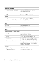
... One 4-pin, USB 2.0-compliant One optional flash memory card slot on internal SD module Video Video type Video memory Integrated Matrox G200 8 MB shared Power AC Power Supply (per power supply) Wattage 870 Watt (High Output) 570 Watt (Energy Smart) Voltage 90-264 VAC, autoranging, 47-63 Hz Heat dissipation 2968.6 BTU/hr maximum (High... maximum (Energy Smart) Maximum inrush current Under typical line conditions and over the entire system ambient operating range, the inrush current may reach 55 A per power supply for 10 ms or less.
... One 4-pin, USB 2.0-compliant One optional flash memory card slot on internal SD module Video Video type Video memory Integrated Matrox G200 8 MB shared Power AC Power Supply (per power supply) Wattage 870 Watt (High Output) 570 Watt (Energy Smart) Voltage 90-264 VAC, autoranging, 47-63 Hz Heat dissipation 2968.6 BTU/hr maximum (High... maximum (Energy Smart) Maximum inrush current Under typical line conditions and over the entire system ambient operating range, the inrush current may reach 55 A per power supply for 10 ms or less.

Getting Started Guide
Page 13
... (8.57 in) 48.25 cm (19.00 in) (includes left and right rack latches) 62.10 cm (24.45 in) (includes power supply with bezel) 35 kg (77 lb) 20.2 kg (44.53 lb) 44.10 cm (17.40 in) 27.40 cm (10....80 in) 62.10 cm (24.45 in) (includes power supply with a maximum humidity gradation of 10°C per hour Getting Started With Your System 11 Storage -40° to 65°C (-40... kg (45.30 lb) Environmental NOTE: For additional information about environmental measurements for specific system configurations, see www.dell.com/environmental_datasheets.
... (8.57 in) 48.25 cm (19.00 in) (includes left and right rack latches) 62.10 cm (24.45 in) (includes power supply with bezel) 35 kg (77 lb) 20.2 kg (44.53 lb) 44.10 cm (17.40 in) 27.40 cm (10....80 in) 62.10 cm (24.45 in) (includes power supply with a maximum humidity gradation of 10°C per hour Getting Started With Your System 11 Storage -40° to 65°C (-40... kg (45.30 lb) Environmental NOTE: For additional information about environmental measurements for specific system configurations, see www.dell.com/environmental_datasheets.
Hardware Owner's Manual
Page 5
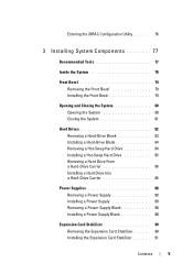
... Installing a Hot-Swap Hard Drive 85 Removing a Hard Drive From a Hard-Drive Carrier 86 Installing a Hard Drive Into a Hard-Drive Carrier 86 Power Supplies 88 Removing a Power Supply 88 Installing a Power Supply 89 Removing a Power Supply Blank 90 Installing a Power Supply Blank 90 Expansion Card Stabilizer 90 Removing the Expansion Card Stabilizer 90 Installing the Expansion Card Stabilizer 91 Contents 5
... Installing a Hot-Swap Hard Drive 85 Removing a Hard Drive From a Hard-Drive Carrier 86 Installing a Hard Drive Into a Hard-Drive Carrier 86 Power Supplies 88 Removing a Power Supply 88 Installing a Power Supply 89 Removing a Power Supply Blank 90 Installing a Power Supply Blank 90 Expansion Card Stabilizer 90 Removing the Expansion Card Stabilizer 90 Installing the Expansion Card Stabilizer 91 Contents 5
Hardware Owner's Manual
Page 8
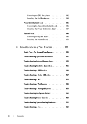
Removing the SAS Backplane 142 Installing the SAS Backplane 144 Power Distribution Board 146 Removing the Power Distribution Board . . . . . 146 Installing the Power Distribution Board . . . . . 147 System Board 148 Removing the System Board 148 Installing the System Board 151 4 Troubleshooting Your System ... a Serial I/O Device 157 Troubleshooting a NIC 157 Troubleshooting a Wet System 158 Troubleshooting a Damaged System 159 Troubleshooting the System Battery 160 Troubleshooting Power Supplies 160 Troubleshooting System Cooling Problems 161 Troubleshooting a Fan 162 8 Contents
Removing the SAS Backplane 142 Installing the SAS Backplane 144 Power Distribution Board 146 Removing the Power Distribution Board . . . . . 146 Installing the Power Distribution Board . . . . . 147 System Board 148 Removing the System Board 148 Installing the System Board 151 4 Troubleshooting Your System ... a Serial I/O Device 157 Troubleshooting a NIC 157 Troubleshooting a Wet System 158 Troubleshooting a Damaged System 159 Troubleshooting the System Battery 160 Troubleshooting Power Supplies 160 Troubleshooting System Cooling Problems 161 Troubleshooting a Fan 162 8 Contents

Hardware Owner's Manual
Page 13
...buttons Description The power-on indicator lights when the system power is on the front and back panels can take up to 25 seconds to display an image, depending on the back flashes blue until one of memory installed in the system. The power button controls the DC power supply output to ...locate a particular system within a rack. NOTE: When powering on the system, the video monitor can be used to the system. NOTE: To force an ungraceful...
...buttons Description The power-on indicator lights when the system power is on the front and back panels can take up to 25 seconds to display an image, depending on the back flashes blue until one of memory installed in the system. The power button controls the DC power supply output to ...locate a particular system within a rack. NOTE: When powering on the system, the video monitor can be used to the system. NOTE: To force an ungraceful...
Hardware Owner's Manual
Page 21
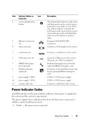
... device to the system. 6 USB connectors (6) 7 iDRAC6 Enterprise port (optional) 8 VFlash media slot (optional) 9 power supply 2 (PS2) 10 power supply 1 (PS1) 11 security cable slot Connects USB devices to locate a particular system within a rack. The ports are USB 2.0-complaint. ... card for the optional iDRAC6 Enterprise card. The power supplies have indicators that show whether power is not connected. Dedicated management port for the optional iDRAC6 Enterprise card. 870-W or 570-W power supply. 870-W or 570-W power supply. Item Indicator, Button, or Icon Connector 2 ...
... device to the system. 6 USB connectors (6) 7 iDRAC6 Enterprise port (optional) 8 VFlash media slot (optional) 9 power supply 2 (PS2) 10 power supply 1 (PS1) 11 security cable slot Connects USB devices to locate a particular system within a rack. The ports are USB 2.0-complaint. ... card for the optional iDRAC6 Enterprise card. The power supplies have indicators that show whether power is not connected. Dedicated management port for the optional iDRAC6 Enterprise card. 870-W or 570-W power supply. 870-W or 570-W power supply. Item Indicator, Button, or Icon Connector 2 ...
Hardware Owner's Manual
Page 22
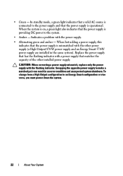
... system is on, a green light also indicates that the power supply is providing DC power to make a matched pair can result in the same system). Replace the power supply that has the flashing indicator with the other installed power supply. CAUTION: When correcting a power supply mismatch, replace only the power supply with the power supply. • Alternating green and amber - • Green - In...
... system is on, a green light also indicates that the power supply is providing DC power to make a matched pair can result in the same system). Replace the power supply that has the flashing indicator with the other installed power supply. CAUTION: When correcting a power supply mismatch, replace only the power supply with the power supply. • Alternating green and amber - • Green - In...
Hardware Owner's Manual
Page 29
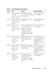
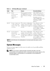
... power supply failure. Check power supply. Check supply communication PSU. cables. "Troubleshooting Power Supplies." See "Troubleshooting Power Supplies." E1614 Power Supply # Specified power supply (### W) error. Power Supply # condition, or a power (### W). error has caused the predictive warning of the source for the specified power supply. E1620 Power Supply # Specified power supply's Check the AC power (### W) AC AC input is missing Power Supplies." If the Check PSU problem persists, see "Troubleshooting Power Supplies." The power supply subsystem...
... power supply failure. Check power supply. Check supply communication PSU. cables. "Troubleshooting Power Supplies." See "Troubleshooting Power Supplies." E1614 Power Supply # Specified power supply (### W) error. Power Supply # condition, or a power (### W). error has caused the predictive warning of the source for the specified power supply. E1620 Power Supply # Specified power supply's Check the AC power (### W) AC AC input is missing Power Supplies." If the Check PSU problem persists, see "Troubleshooting Power Supplies." The power supply subsystem...
Hardware Owner's Manual
Page 30
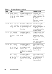
...channel check error. Check the SEL for 10 seconds and restart the system. Remove AC power to the system, reduce the hardware configuration or install higher-wattage power supplies, and then restart the system. E1711 PCI parity error on Slot #. The system ... Specifications outlined in PCI "Troubleshooting configuration space at bus Expansion Cards." ##, device ##, function ##. E1629 Power required > PSU wattage. Turn off power to the system for more power than the power supplies can provide, even with matching = ### W, PSU2 wattage. PCI parity error on Bus ## Device ...
...channel check error. Check the SEL for 10 seconds and restart the system. Remove AC power to the system, reduce the hardware configuration or install higher-wattage power supplies, and then restart the system. E1711 PCI parity error on Slot #. The system ... Specifications outlined in PCI "Troubleshooting configuration space at bus Expansion Cards." ##, device ##, function ##. E1629 Power required > PSU wattage. Turn off power to the system for more power than the power supplies can provide, even with matching = ### W, PSU2 wattage. PCI parity error on Bus ## Device ...
Hardware Owner's Manual
Page 37
...or acronym used in the table, check the documentation for an explanation of a possible problem with the system. install higher-wattage power supplies, and then restart the system. NOTE: If you of the message and recommended action. Warns predictively that is running when the... documentation for the application that the RAID battery has less than system, reduce the Check PSU and what the power supply can boot if install higher-wattage configuration. power supplies, and then restart the system. Table 1-1. NOTE: For the full name of charge left. LCD Status Messages...
...or acronym used in the table, check the documentation for an explanation of a possible problem with the system. install higher-wattage power supplies, and then restart the system. NOTE: If you of the message and recommended action. Warns predictively that is running when the... documentation for the application that the RAID battery has less than system, reduce the Check PSU and what the power supply can boot if install higher-wattage configuration. power supplies, and then restart the system. Table 1-1. NOTE: For the full name of charge left. LCD Status Messages...
Hardware Owner's Manual
Page 40
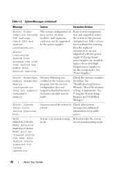
... previous configuration. BIOS MANUFACTURING MODE detected. Alert! If Energy Smart power supplies are installed, replace them with this warning, then the replaced component(s) are not supported with High Output power supplies to take the system mode. Check the memory modules for possible ...system setup program, but the current configuration does not support redundant memory. A memory module may power down without this power supply. The system configuration of manufacturing mode. 40 About Your System System Messages (continued) Message Causes Corrective Actions Alert!
... previous configuration. BIOS MANUFACTURING MODE detected. Alert! If Energy Smart power supplies are installed, replace them with this warning, then the replaced component(s) are not supported with High Output power supplies to take the system mode. Check the memory modules for possible ...system setup program, but the current configuration does not support redundant memory. A memory module may power down without this power supply. The system configuration of manufacturing mode. 40 About Your System System Messages (continued) Message Causes Corrective Actions Alert!
Hardware Owner's Manual
Page 53
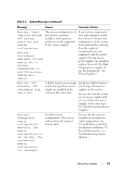
... run but with this warning, then the replaced component(s) are installed, replace them with the High Output power supplies to use the components. The system will reboot. If the system boots without this power supply. If Energy Smart power supplies are not supported with reduced functionality. Warning! About Your System 53 System Messages (continued) Message Causes...
... run but with this warning, then the replaced component(s) are installed, replace them with the High Output power supplies to use the components. The system will reboot. If the system boots without this power supply. If Energy Smart power supplies are not supported with reduced functionality. Warning! About Your System 53 System Messages (continued) Message Causes...
Hardware Owner's Manual
Page 79
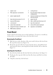
... pull the bezel away from the chassis, removing the bezel tabs from the slots as shown in the chassis. 1 system cover 3 PCIe expansion card slots (5) 5 power supply bays (2) 7 heat sink and processor (1 or 2) 9 internal USB module 11 control panel 13 optical drive (optional) 15 integrated storage controller card 17 RAID battery (optional...
... pull the bezel away from the chassis, removing the bezel tabs from the slots as shown in the chassis. 1 system cover 3 PCIe expansion card slots (5) 5 power supply bays (2) 7 heat sink and processor (1 or 2) 9 internal USB module 11 control panel 13 optical drive (optional) 15 integrated storage controller card 17 RAID battery (optional...


