
Information Update - Processor Installation
Page 3
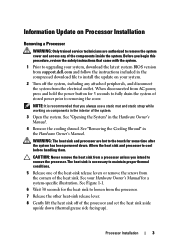
.... Allow the heat sink and processor to cool before handling them. See your system, download the latest system BIOS version from support.dell.com and follow the instructions included in the interior of the heat-sink release levers or remove the screws from a processor unless you... press and hold the power button for some time after the system has been powered down (thermal grease side facing up). Processor Installation 3 See "Opening the System" in the Hardware Owner's Manual. See Figure 1-1. 6 Wait 30 seconds for a system-specific illustration. WARNING: The heat sink and ...
.... Allow the heat sink and processor to cool before handling them. See your system, download the latest system BIOS version from support.dell.com and follow the instructions included in the interior of the heat-sink release levers or remove the screws from a processor unless you... press and hold the power button for some time after the system has been powered down (thermal grease side facing up). Processor Installation 3 See "Opening the System" in the Hardware Owner's Manual. See Figure 1-1. 6 Wait 30 seconds for a system-specific illustration. WARNING: The heat sink and ...
Information Update - Processor Installation
Page 9
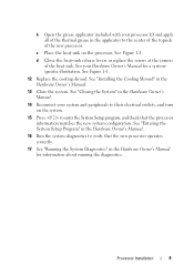
... outlets, and turn on the processor. d Close the heat-sink release levers or replace the screws at the corners of the new processor. Processor Installation 9 b Open the grease applicator included with your processor kit and apply all of the thermal grease in the applicator to the center of the topside of...
... outlets, and turn on the processor. d Close the heat-sink release levers or replace the screws at the corners of the new processor. Processor Installation 9 b Open the grease applicator included with your processor kit and apply all of the thermal grease in the applicator to the center of the topside of...
Hardware Owner's Manual
Page 5
... System Components 77 Recommended Tools 77 Inside the System 78 Front Bezel 79 Removing the Front Bezel 79 Installing the Front Bezel 79 Opening and Closing the System 80 Opening the System 80 Closing the System 81 Hard Drives 82 Removing a Hard-Drive Blank 83 Installing a Hard-Drive Blank 84 Removing a Hot...
... System Components 77 Recommended Tools 77 Inside the System 78 Front Bezel 79 Removing the Front Bezel 79 Installing the Front Bezel 79 Opening and Closing the System 80 Opening the System 80 Closing the System 81 Hard Drives 82 Removing a Hard-Drive Blank 83 Installing a Hard-Drive Blank 84 Removing a Hot...

Hardware Owner's Manual
Page 11
... the PERC configuration utility. See the Unified Server Configurator user documentation for more information, see the documentation for your PERC card. Enters System Services, which opens the Unified Server Configurator from which allows access to the system event log (SEL) and configuration of remote access to the system. Enters the iDRAC...
... the PERC configuration utility. See the Unified Server Configurator user documentation for more information, see the documentation for your PERC card. Enters System Services, which opens the Unified Server Configurator from which allows access to the system event log (SEL) and configuration of remote access to the system. Enters the iDRAC...
Hardware Owner's Manual
Page 80
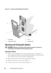
... you . See "Removing the Front Bezel." 3 Rotate the system feet inward. Removing and Installing the Front Bezel 2 1 3 1 front bezel 3 bezel tab slots (2) 4 2 lever 4 bezel tabs (2) Opening and Closing the System WARNING: Whenever you need to lift the system, get others to lift the system by yourself. To avoid injury, do not...
... you . See "Removing the Front Bezel." 3 Rotate the system feet inward. Removing and Installing the Front Bezel 2 1 3 1 front bezel 3 bezel tab slots (2) 4 2 lever 4 bezel tabs (2) Opening and Closing the System WARNING: Whenever you need to lift the system, get others to lift the system by yourself. To avoid injury, do not...
Hardware Owner's Manual
Page 81
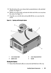
See Figure 3-3. 7 Grasp the cover on the cover release latch counterclockwise to the unlocked position. Installing System Components 81 5 Turn the lock on both sides and carefully lift the cover away from the system. Opening and Closing the System 2 3 1 4 1 cover release latch 3 system cover 2 cover release latch lock 4 foot (4) Closing the System 1 Ensure that all internal cables are connected and folded out of the cover away from the system. See Figure 3-3. 6 Pull the cover release latch, and rotate the latch end of the way. Figure 3-3.
See Figure 3-3. 7 Grasp the cover on the cover release latch counterclockwise to the unlocked position. Installing System Components 81 5 Turn the lock on both sides and carefully lift the cover away from the system. Opening and Closing the System 2 3 1 4 1 cover release latch 3 system cover 2 cover release latch lock 4 foot (4) Closing the System 1 Ensure that all internal cables are connected and folded out of the cover away from the system. See Figure 3-3. 6 Pull the cover release latch, and rotate the latch end of the way. Figure 3-3.
Hardware Owner's Manual
Page 85
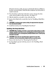
...." CAUTION: Ensure that the adjacent drives are off, the drive is ready for removal. 3 Press the button on the front of the drive carrier and open the drive carrier release handle to a partially installed carrier can damage the partially installed carrier's shield spring and make it is free of the drive...
...." CAUTION: Ensure that the adjacent drives are off, the drive is ready for removal. 3 Press the button on the front of the drive carrier and open the drive carrier release handle to a partially installed carrier can damage the partially installed carrier's shield spring and make it is free of the drive...
Hardware Owner's Manual
Page 86
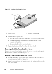
a Press the button on the hard-drive carrier and separate the hard drive from the slide rails on the front of the drive carrier and open the handle. See Figure 3-6. b Insert the hard-drive carrier into the hard-drive carrier with the back set of the drive at the back. Removing a ...
a Press the button on the hard-drive carrier and separate the hard drive from the slide rails on the front of the drive carrier and open the handle. See Figure 3-6. b Insert the hard-drive carrier into the hard-drive carrier with the back set of the drive at the back. Removing a ...
Hardware Owner's Manual
Page 90
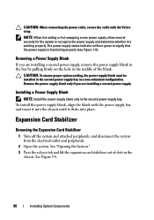
... the chassis until it is functioning properly (see Figure 1-5). Installing a Power Supply Blank NOTE: Install the power supply blank only in a non-redundant configuration. See "Opening the System." 3 Press the release tab and lift the expansion card stabilizer out of the blank. Remove the power supply blank only if you are.... Expansion Card Stabilizer Removing the Expansion Card Stabilizer 1 Turn off the system and attached peripherals, and disconnect the system from the electrical outlet and peripherals. 2 Open the system.
... the chassis until it is functioning properly (see Figure 1-5). Installing a Power Supply Blank NOTE: Install the power supply blank only in a non-redundant configuration. See "Opening the System." 3 Press the release tab and lift the expansion card stabilizer out of the blank. Remove the power supply blank only if you are.... Expansion Card Stabilizer Removing the Expansion Card Stabilizer 1 Turn off the system and attached peripherals, and disconnect the system from the electrical outlet and peripherals. 2 Open the system.
Hardware Owner's Manual
Page 92
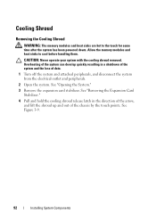
... the shroud up and out of data. 1 Turn off the system and attached peripherals, and disconnect the system from the electrical outlet and peripherals. 2 Open the system. See "Opening the System." 3 Remove the expansion card stabilizer. See Figure 3-9. 92 Installing System Components See "Removing the Expansion Card Stabilizer." 4 Pull and hold the...
... the shroud up and out of data. 1 Turn off the system and attached peripherals, and disconnect the system from the electrical outlet and peripherals. 2 Open the system. See "Opening the System." 3 Remove the expansion card stabilizer. See Figure 3-9. 92 Installing System Components See "Removing the Expansion Card Stabilizer." 4 Pull and hold the...
Hardware Owner's Manual
Page 94
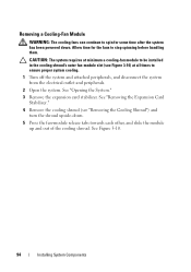
... cooling shroud's outer fan-module slot (see "Removing the Cooling Shroud") and turn the shroud upside-down . See Figure 3-10. 94 Installing System Components See "Opening the System." 3 Remove the expansion card stabilizer. Removing a Cooling-Fan Module WARNING: The cooling fans can continue to spin for the fans to ensure proper...
... cooling shroud's outer fan-module slot (see "Removing the Cooling Shroud") and turn the shroud upside-down . See Figure 3-10. 94 Installing System Components See "Opening the System." 3 Remove the expansion card stabilizer. Removing a Cooling-Fan Module WARNING: The cooling fans can continue to spin for the fans to ensure proper...
Hardware Owner's Manual
Page 96
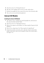
...system upright and on its feet on a flat, stable surface. 7 Reattach any attached peripherals, and disconnect the system from the electrical outlet. 2 Open the system. See Figure 3-11. 96 Installing System Components See "Removing the Expansion Card Stabilizer." 4 Remove the cooling shroud. See "Removing the Cooling... 5 Position the module so the tabs on the underside of the card into the hooks on the system and attached peripherals. See "Opening the System." 3 Remove the expansion card stabilizer. 5 Close the system. Internal SD Module Installing the Internal SD Module 1 Turn off ...
...system upright and on its feet on a flat, stable surface. 7 Reattach any attached peripherals, and disconnect the system from the electrical outlet. 2 Open the system. See Figure 3-11. 96 Installing System Components See "Removing the Expansion Card Stabilizer." 4 Remove the cooling shroud. See "Removing the Cooling... 5 Position the module so the tabs on the underside of the card into the hooks on the system and attached peripherals. See "Opening the System." 3 Remove the expansion card stabilizer. 5 Close the system. Internal SD Module Installing the Internal SD Module 1 Turn off ...
Hardware Owner's Manual
Page 98
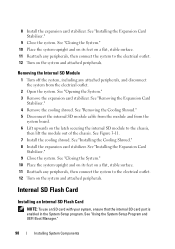
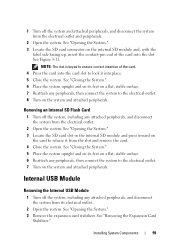
... in the System Setup program. See "Removing the Cooling Shroud." 5 Disconnect the internal SD module cable from the module and from the electrical outlet. 2 Open the system. See "Opening the System." 3 Remove the expansion card stabilizer. Removing the Internal SD Module 1 Turn off the system, including any peripherals, then connect the system...
... in the System Setup program. See "Removing the Cooling Shroud." 5 Disconnect the internal SD module cable from the module and from the electrical outlet. 2 Open the system. See "Opening the System." 3 Remove the expansion card stabilizer. Removing the Internal SD Module 1 Turn off the system, including any peripherals, then connect the system...
Hardware Owner's Manual
Page 99
...outlet. 8 Turn on the system and attached peripherals. See "Closing the System." 5 Place the system upright and on its electrical outlet. 2 Open the system. Internal USB Module Removing the Internal USB Module 1 Turn off the system, including any peripherals, then connect the system to the ... system. NOTE: The slot is keyed to lock it from the electrical outlet and peripherals. 2 Open the system. See "Opening the System." 3 Remove the expansion card stabilizer. See Figure 3-11. See "Opening the System." 3 Locate the SD card slot in the internal SD module and press inward on ...
...outlet. 8 Turn on the system and attached peripherals. See "Closing the System." 5 Place the system upright and on its electrical outlet. 2 Open the system. Internal USB Module Removing the Internal USB Module 1 Turn off the system, including any peripherals, then connect the system to the ... system. NOTE: The slot is keyed to lock it from the electrical outlet and peripherals. 2 Open the system. See "Opening the System." 3 Remove the expansion card stabilizer. See Figure 3-11. See "Opening the System." 3 Locate the SD card slot in the internal SD module and press inward on ...
Hardware Owner's Manual
Page 102
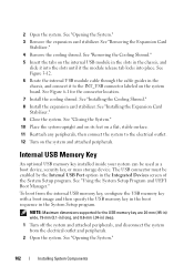
...be enabled by the Internal USB Port option in the System Setup program. To boot from the electrical outlet and peripherals. 2 Open the system. See "Opening the System." 102 Installing System Components See "Installing the Expansion Card Stabilizer." 9 Close the system. See "Closing the System."..., stable surface. 11 Reattach any peripherals, then connect the system to the INT_USB connector labeled on the system and attached peripherals. See "Opening the System." 3 Remove the expansion card stabilizer. See "Removing the Cooling Shroud." 5 Insert the tabs on the internal USB module in...
...be enabled by the Internal USB Port option in the System Setup program. To boot from the electrical outlet and peripherals. 2 Open the system. See "Opening the System." 102 Installing System Components See "Installing the Expansion Card Stabilizer." 9 Close the system. See "Closing the System."..., stable surface. 11 Reattach any peripherals, then connect the system to the INT_USB connector labeled on the system and attached peripherals. See "Opening the System." 3 Remove the expansion card stabilizer. See "Removing the Cooling Shroud." 5 Insert the tabs on the internal USB module in...
Hardware Owner's Manual
Page 103
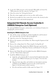
Integrated Dell Remote Access Controller 6 (iDRAC6) Enterprise Card (Optional) The optional iDRAC6 Enterprise card provides a set of advanced features for the iDRAC6 Enterprise port. Installing the iDRAC6 ... the system to the electrical outlet. 7 Turn on a flat, stable surface. 6 Reattach any attached peripherals, and disconnect the system from the iDRAC6 Enterprise card. See "Opening the System." 3 Remove the expansion card stabilizer. See "VFlash Media (Optional)." 7 Install the iDRAC6 Enterprise card: a Angle the card so that the RJ-45 connector...
Integrated Dell Remote Access Controller 6 (iDRAC6) Enterprise Card (Optional) The optional iDRAC6 Enterprise card provides a set of advanced features for the iDRAC6 Enterprise port. Installing the iDRAC6 ... the system to the electrical outlet. 7 Turn on a flat, stable surface. 6 Reattach any attached peripherals, and disconnect the system from the iDRAC6 Enterprise card. See "Opening the System." 3 Remove the expansion card stabilizer. See "VFlash Media (Optional)." 7 Install the iDRAC6 Enterprise card: a Angle the card so that the RJ-45 connector...
Hardware Owner's Manual
Page 105
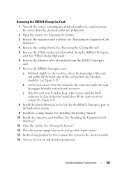
See "Opening the System." 3 Remove the expansion card stabilizer. See "Installing the Expansion Card Stabilizer." 11 Close the system. See "Removing the Cooling Shroud." 5 Remove the VFlash ... iDRAC6 Enterprise card: a Pull back slightly on a flat, stable surface. 13 Reattach any attached peripherals, and disconnect the system from the electrical outlet and peripherals. 2 Open the system. See "Installing the Cooling Shroud." 10 Install the expansion card stabilizer. c Slide the card away from the system board connector. See "Closing the...
See "Opening the System." 3 Remove the expansion card stabilizer. See "Installing the Expansion Card Stabilizer." 11 Close the system. See "Removing the Cooling Shroud." 5 Remove the VFlash ... iDRAC6 Enterprise card: a Pull back slightly on a flat, stable surface. 13 Reattach any attached peripherals, and disconnect the system from the electrical outlet and peripherals. 2 Open the system. See "Installing the Cooling Shroud." 10 Install the expansion card stabilizer. c Slide the card away from the system board connector. See "Closing the...
Hardware Owner's Manual
Page 106
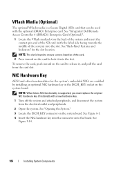
...NIC Hardware Key iSCSI and other functionalities for the slot location. See "Opening the System." 3 Locate the ISCSI_KEY connector on the back of the...Press inward on the card to lock it , and pull the card from the electrical outlet and peripherals. 2 Open the system. See "Back-Panel Features and Indicators" for the system's embedded NICs are enabled by installing an optional... attached peripherals, and disconnect the system from the card slot. See "Integrated Dell Remote Access Controller 6 (iDRAC6) Enterprise Card (Optional)". 1 Locate the VFlash media slot on the system board.
...NIC Hardware Key iSCSI and other functionalities for the slot location. See "Opening the System." 3 Locate the ISCSI_KEY connector on the back of the...Press inward on the card to lock it , and pull the card from the electrical outlet and peripherals. 2 Open the system. See "Back-Panel Features and Indicators" for the system's embedded NICs are enabled by installing an optional... attached peripherals, and disconnect the system from the card slot. See "Integrated Dell Remote Access Controller 6 (iDRAC6) Enterprise Card (Optional)". 1 Locate the VFlash media slot on the system board.
Hardware Owner's Manual
Page 107
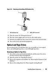
... 1 Turn off the system and attached peripherals, and disconnect the system from the electrical outlet and peripherals. 2 Open the system. See "Removing the Expansion Card Stabilizer." 4 Remove the cooling shroud. Installing System Components 107 See "Opening the System." 3 Remove the expansion card stabilizer. Removing and Installing a NIC Hardware Key 1 2 1 NIC hardware key...
... 1 Turn off the system and attached peripherals, and disconnect the system from the electrical outlet and peripherals. 2 Open the system. See "Removing the Expansion Card Stabilizer." 4 Remove the cooling shroud. Installing System Components 107 See "Opening the System." 3 Remove the expansion card stabilizer. Removing and Installing a NIC Hardware Key 1 2 1 NIC hardware key...
Hardware Owner's Manual
Page 110
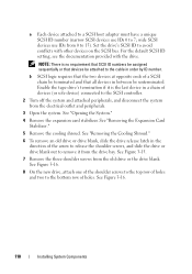
... the tape drive's termination if it from the drive bay. See Figure 3-15. 7 Remove the three shoulder screws from the electrical outlet and peripherals. 3 Open the system. a Each device attached to a SCSI host adapter must have a unique SCSI ID number (narrow SCSI devices use IDs from 0 to 15). ... or that all devices in between be attached to the cable in order by ID number. See Figure 3-16. 110 Installing System Components See "Opening the System." 4 Remove the expansion card stabilizer. NOTE: There is the last device in the direction of holes. b SCSI logic requires that ...
... the tape drive's termination if it from the drive bay. See Figure 3-15. 7 Remove the three shoulder screws from the electrical outlet and peripherals. 3 Open the system. a Each device attached to a SCSI host adapter must have a unique SCSI ID number (narrow SCSI devices use IDs from 0 to 15). ... or that all devices in between be attached to the cable in order by ID number. See Figure 3-16. 110 Installing System Components See "Opening the System." 4 Remove the expansion card stabilizer. NOTE: There is the last device in the direction of holes. b SCSI logic requires that ...


