

Glossary
Page 5
...provided by software. MB - Mbps - MBR - Master boot record. Milliampere-hour(s). A managed system is monitored and managed using Dell OpenManage™ Server Administrator. However, when referring to serve specific storage needs. MBps - memory - A portable flash memory storage ...number, in your system that contains the CIM schema definition. ms - memory key - mirroring - See also striping and RAID. Network interface controller. management station - Megabytes per second. Millisecond(s). An area in the system's RAM. Mirroring functionality is often rounded to a...
...provided by software. MB - Mbps - MBR - Master boot record. Milliampere-hour(s). A managed system is monitored and managed using Dell OpenManage™ Server Administrator. However, when referring to serve specific storage needs. MBps - memory - A portable flash memory storage ...number, in your system that contains the CIM schema definition. ms - memory key - mirroring - See also striping and RAID. Network interface controller. management station - Megabytes per second. Millisecond(s). An area in the system's RAM. Mirroring functionality is often rounded to a...

Glossary
Page 6
... the number of pixels across by the number of data. processor - Nonvolatile random-access memory. parity stripe - PERC - PowerEdge RAID controller. pixel - POST - Software written for maintaining the date, time, and system configuration information. Remote access controller. 6 Nonmaskable interrupt. ns - NVRAM - NVRAM is associated with multiple power outlets that is used for one processor...
... the number of pixels across by the number of data. processor - Nonvolatile random-access memory. parity stripe - PERC - PowerEdge RAID controller. pixel - POST - Software written for maintaining the date, time, and system configuration information. Remote access controller. 6 Nonmaskable interrupt. ns - NVRAM - NVRAM is associated with multiple power outlets that is used for one processor...

Glossary
Page 8
...a crossover cable. See also guarding, mirroring, and RAID. system configuration information - termination - U-DIMM - A USB connector provides a single connection point for multiple USB-compliant devices, such as the processor(s), RAM, controllers for video adapters with greater resolution and color display ...to connect to I/O devices. SVGA - VGA and SVGA are connected in the cable. See RAM. System Setup program - Transmission Control Protocol/Internet Protocol. Some devices (such as password protection. A port on the same set of an electrical failure. UPS - A...
...a crossover cable. See also guarding, mirroring, and RAID. system configuration information - termination - U-DIMM - A USB connector provides a single connection point for multiple USB-compliant devices, such as the processor(s), RAM, controllers for video adapters with greater resolution and color display ...to connect to I/O devices. SVGA - VGA and SVGA are connected in the cable. See RAM. System Setup program - Transmission Control Protocol/Internet Protocol. Some devices (such as password protection. A port on the same set of an electrical failure. UPS - A...
Glossary
Page 46
... - Milliampere-hour Mb - Megabit 1 Mb = 1,048,576 MB - Object Identifier PCI - Network Interface Controller NMI - Millimeter MOF - Managed Object Format CIM ASCII ms - Power distribution unit PDU PERC - Master boot record MHz - Nanosecond NVRAM - MAC Media Access Control mAh - PowerEdge RAID 46 Megabytes per second MBps - Nonvolatile random access memory NVRAM OID - Network Attached...
... - Milliampere-hour Mb - Megabit 1 Mb = 1,048,576 MB - Object Identifier PCI - Network Interface Controller NMI - Millimeter MOF - Managed Object Format CIM ASCII ms - Power distribution unit PDU PERC - Master boot record MHz - Nanosecond NVRAM - MAC Media Access Control mAh - PowerEdge RAID 46 Megabytes per second MBps - Nonvolatile random access memory NVRAM OID - Network Attached...
Glossary
Page 47
... self-test OS RAM PXE - Serial Advanced Technology Attachment SCSI - Small computer system interface I/O SD SD SDRAM - Remote access controller RAID - Redundant array of independent disks RAID には、RAID 0、RAID 1、RAID 5、 RAID 10 RAID 50 RAM - Storage Area Network SAS - Serial-attached SCSI SCSI)。 SATA - Second(秒)。 SEL...
... self-test OS RAM PXE - Serial Advanced Technology Attachment SCSI - Small computer system interface I/O SD SD SDRAM - Remote access controller RAID - Redundant array of independent disks RAID には、RAID 0、RAID 1、RAID 5、 RAID 10 RAID 50 RAM - Storage Area Network SAS - Serial-attached SCSI SCSI)。 SATA - Second(秒)。 SEL...
Glossary
Page 56
...; CIM ASCII ms Millisecond NAS Network Attached Storage NAS NAS NIC Network Interface Controller NMI Nonmaskable Interrupt NMI ns Nanosecond NVRAM Nonvolatile Random-Access Memory NVRAM OID Object Identifier PCI Peripheral Component Interconnect PDU Power Distribution Unit PERC - PowerEdge RAID POST Power-On Self-Test POST RAM PXE Preboot eXecution Environment LAN R-DIMM...
...; CIM ASCII ms Millisecond NAS Network Attached Storage NAS NAS NIC Network Interface Controller NMI Nonmaskable Interrupt NMI ns Nanosecond NVRAM Nonvolatile Random-Access Memory NVRAM OID Object Identifier PCI Peripheral Component Interconnect PDU Power Distribution Unit PERC - PowerEdge RAID POST Power-On Self-Test POST RAM PXE Preboot eXecution Environment LAN R-DIMM...
Glossary
Page 57
... Analysis and Reporting Technology BIOS SMP Symmetric Multiprocessing 2 I /O SD 카드 - RAC Remote Access Controller RAID Redundant Array of Independent Disk RAID RAID 0, RAID 1, RAID 5, RAID 10 및 RAID 50 RAM Random-Access Memory RAM ROM Read-Only Memory ROM ROM ROM POST ROMB RAID(RAID On Motherboard SAN Storage Area Network SAS SCSI(Serial-Attached SCSI SATA Serial Advanced...
... Analysis and Reporting Technology BIOS SMP Symmetric Multiprocessing 2 I /O SD 카드 - RAC Remote Access Controller RAID Redundant Array of Independent Disk RAID RAID 0, RAID 1, RAID 5, RAID 10 및 RAID 50 RAM Random-Access Memory RAM ROM Read-Only Memory ROM ROM ROM POST ROMB RAID(RAID On Motherboard SAN Storage Area Network SAS SCSI(Serial-Attached SCSI SATA Serial Advanced...
Dell PowerEdge Deployment Guide
Page 4
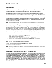
...Unified Server Configurator is not C:. 2. Unified Server Configurator (USC) Deployment The Lifecycle Controller is an embedded system management tool that you normally would in order for your operating system, RAID, and to download drivers and firmware updates. Page 2 This document will briefly cover...The purpose of this document is to provide tips on -motherboard). The 11th Generation PowerEdge servers include 5709-based LOMs (LAN-on deploying Microsoft® operating systems to Dell PowerEdge servers. This document will not cover how to support iSCSI and TOE. This ...
...Unified Server Configurator is not C:. 2. Unified Server Configurator (USC) Deployment The Lifecycle Controller is an embedded system management tool that you normally would in order for your operating system, RAID, and to download drivers and firmware updates. Page 2 This document will briefly cover...The purpose of this document is to provide tips on -motherboard). The 11th Generation PowerEdge servers include 5709-based LOMs (LAN-on deploying Microsoft® operating systems to Dell PowerEdge servers. This document will not cover how to support iSCSI and TOE. This ...
Hardware Owner's Manual
Page 7
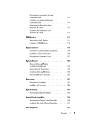
Removing an Integrated Storage Controller Card 112 Installing an Integrated Storage Controller Card 114 Removing the Expansion Card Stabilizer Bracket 115 Installing the Expansion Card Stabilizer Bracket 116 RAID Battery 117 Removing a RAID Battery 117 Installing a RAID Battery 118 Expansion Cards 118 Expansion Card Installation ...131 Removing a Processor 131 Installing a Processor 134 System Battery 136 Replacing the System Battery 136 Control Panel Assembly 138 Removing the Control Panel Assembly 138 Installing the Control Panel Assembly 141 SAS Backplane 142 Contents 7
Removing an Integrated Storage Controller Card 112 Installing an Integrated Storage Controller Card 114 Removing the Expansion Card Stabilizer Bracket 115 Installing the Expansion Card Stabilizer Bracket 116 RAID Battery 117 Removing a RAID Battery 117 Installing a RAID Battery 118 Expansion Cards 118 Expansion Card Installation ...131 Removing a Processor 131 Installing a Processor 134 System Battery 136 Replacing the System Battery 136 Control Panel Assembly 138 Removing the Control Panel Assembly 138 Installing the Control Panel Assembly 141 SAS Backplane 142 Contents 7
Hardware Owner's Manual
Page 26
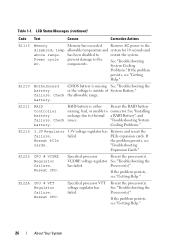
...26 About Your System E1210 Motherboard CMOS battery is missing See "Troubleshooting the battery or the voltage is either Reseat the RAID battery Controller missing, bad, or unable to the disabled, temp allowable temperature and system for 10 seconds and above range. PCIe expansion...continued) Code Text Causes Corrective Actions E1116 Memory Memory has exceeded Remove AC power to connector. has been disabled to thermal a RAID Battery", and failure. See "Installing battery recharge due to restart the system. prevent damage to the components. If Reseat PCIe the...
...26 About Your System E1210 Motherboard CMOS battery is missing See "Troubleshooting the battery or the voltage is either Reseat the RAID battery Controller missing, bad, or unable to the disabled, temp allowable temperature and system for 10 seconds and above range. PCIe expansion...continued) Code Text Causes Corrective Actions E1116 Memory Memory has exceeded Remove AC power to connector. has been disabled to thermal a RAID Battery", and failure. See "Installing battery recharge due to restart the system. prevent damage to the components. If Reseat PCIe the...
Hardware Owner's Manual
Page 37
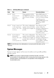
... Corrective Actions W1228 RAID Controller battery capacity < 24hr. See "Installing a RAID Battery." W1627 Power required The system configuration Turn off power to the > PSU wattage. W1628 Performance The system configuration Turn off power to the degraded. If problem persists, replace RAID battery. provide. ...config. Warns predictively that is running when the message appears or the operating system's documentation for the application that the RAID battery has less than 24 hours of charge left. install higher-wattage power supplies, and then restart the system....
... Corrective Actions W1228 RAID Controller battery capacity < 24hr. See "Installing a RAID Battery." W1627 Power required The system configuration Turn off power to the > PSU wattage. W1628 Performance The system configuration Turn off power to the degraded. If problem persists, replace RAID battery. provide. ...config. Warns predictively that is running when the message appears or the operating system's documentation for the application that the RAID battery has less than 24 hours of charge left. install higher-wattage power supplies, and then restart the system....
Hardware Owner's Manual
Page 64
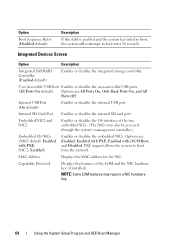
...of the LOM and the NIC hardware key (if installed). NOTE: Some LOM features may also be accessed through the system's management controller.) Embedded Gb NICx (NIC1 default: Enabled with iSCSI Boot, and Disabled. Internal SD Card Port Enables or disables the internal SD ... NICs. MAC Address Displays the MAC address for the NIC. Integrated Devices Screen Option Description Integrated SAS/RAID Controller (Enabled default) Enables or disables the integrated storage controller. PXE support allows the system to boot after 30 seconds. Internal USB Port (On default) Enables ...
...of the LOM and the NIC hardware key (if installed). NOTE: Some LOM features may also be accessed through the system's management controller.) Embedded Gb NICx (NIC1 default: Enabled with iSCSI Boot, and Disabled. Internal SD Card Port Enables or disables the internal SD ... NICs. MAC Address Displays the MAC address for the NIC. Integrated Devices Screen Option Description Integrated SAS/RAID Controller (Enabled default) Enables or disables the integrated storage controller. PXE support allows the system to boot after 30 seconds. Internal USB Port (On default) Enables ...
Hardware Owner's Manual
Page 79
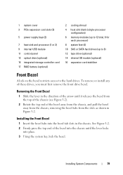
... the chassis. 1 system cover 3 PCIe expansion card slots (5) 5 power supply bays (2) 7 heat sink and processor (1 or 2) 9 internal USB module 11 control panel 13 optical drive (optional) 15 integrated storage controller card 17 RAID battery (optional) 2 cooling shroud 4 heat sink blank (single-processor configuration) 6 memory modules (up to 12 total, 6 for each processor) 8 system...
... the chassis. 1 system cover 3 PCIe expansion card slots (5) 5 power supply bays (2) 7 heat sink and processor (1 or 2) 9 internal USB module 11 control panel 13 optical drive (optional) 15 integrated storage controller card 17 RAID battery (optional) 2 cooling shroud 4 heat sink blank (single-processor configuration) 6 memory modules (up to 12 total, 6 for each processor) 8 system...
Hardware Owner's Manual
Page 84
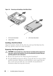
See your controller documentation for removal. Wait until the release lever clicks into place. Removing and Installing a Hard Drive Blank 1 2 3 3 1 3.5-in hard drive blank 3 release latch 2 2.5-in hard ... a Hard-Drive Blank Align the hard-drive blank with your operating system supports hotswap drive removal and installation. See "Removing the Front Bezel." 2 From the RAID management software, prepare the drive for information about hot-swap drive removal. 84 Installing System Components Figure 3-4. See the documentation provided with the drive bay...
See your controller documentation for removal. Wait until the release lever clicks into place. Removing and Installing a Hard Drive Blank 1 2 3 3 1 3.5-in hard drive blank 3 release latch 2 2.5-in hard ... a Hard-Drive Blank Align the hard-drive blank with your operating system supports hotswap drive removal and installation. See "Removing the Front Bezel." 2 From the RAID management software, prepare the drive for information about hot-swap drive removal. 84 Installing System Components Figure 3-4. See the documentation provided with the drive bay...
Hardware Owner's Manual
Page 112
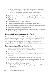
... on the system and attached peripherals. 18 (Optional) Test the drive by the version of the storage controller included with your system's internal hard drives. The controller supports SAS and SATA hard drives and also enables you are installing a SCSI tape drive, connect the SCSI... interface cable in RAID configurations as supported by running the system diagnostics. Removing an Integrated Storage Controller Card 1 Turn off the system, including any peripherals, then connect the system to the electrical ...
... on the system and attached peripherals. 18 (Optional) Test the drive by the version of the storage controller included with your system's internal hard drives. The controller supports SAS and SATA hard drives and also enables you are installing a SCSI tape drive, connect the SCSI... interface cable in RAID configurations as supported by running the system diagnostics. Removing an Integrated Storage Controller Card 1 Turn off the system, including any peripherals, then connect the system to the electrical ...
Hardware Owner's Manual
Page 113
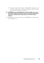
See Figure 3-17. See Figure 3-17. The LED indicates that data is lit. Installing System Components 113 b Grasp the storage card by its edge, carefully pull the card up to pull the card up and out of the card guides. CAUTION: Disconnecting the RAID battery cable from a PERC card can cause data loss if the "dirty cache" LED on the card is still cached in controller memory and the data was not cleared at system shutdown. 6 If applicable and necessary, disconnect the RAID battery cable from the storage-card connector, and continue to remove it from the card.
See Figure 3-17. See Figure 3-17. The LED indicates that data is lit. Installing System Components 113 b Grasp the storage card by its edge, carefully pull the card up to pull the card up and out of the card guides. CAUTION: Disconnecting the RAID battery cable from a PERC card can cause data loss if the "dirty cache" LED on the card is still cached in controller memory and the data was not cleared at system shutdown. 6 If applicable and necessary, disconnect the RAID battery cable from the storage-card connector, and continue to remove it from the card.
Hardware Owner's Manual
Page 114
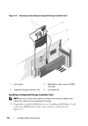
Removing and Installing an Integrated Storage Controller Card 1 2 3 4 1 data cables 3 integrated storage controller card 2 RAID battery cable connector (PERC card only) 4 card guides (2) Installing an Integrated Storage Controller Card NOTE: Be sure to connect the cables according to the connector on the cables. See Figure 3-17. 114 Installing System Components Figure 3-17. The cables are not operational if reversed. 1 If applicable, install the RAID battery (see "Installing a RAID Battery") and connect the RAID battery cable to the connector labels on the card.
Removing and Installing an Integrated Storage Controller Card 1 2 3 4 1 data cables 3 integrated storage controller card 2 RAID battery cable connector (PERC card only) 4 card guides (2) Installing an Integrated Storage Controller Card NOTE: Be sure to connect the cables according to the connector on the cables. See Figure 3-17. 114 Installing System Components Figure 3-17. The cables are not operational if reversed. 1 If applicable, install the RAID battery (see "Installing a RAID Battery") and connect the RAID battery cable to the connector labels on the card.
Hardware Owner's Manual
Page 116
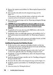
... release tab on the expansion card stabilizer bracket over the four metal guides in controller memory and the data was not cleared at system shutdown. 6 If applicable and necessary, disconnect the RAID battery cable from the integrated storage card. See Figure 3-27. See "Installing ...an Expansion Card." 3 If applicable, reconnect the RAID battery cable to the integrated storage card. To disconnect a cable, press the blue latches on both sides of the chassis. See "Installing an Integrated Storage Controller Card." 5 Reconnect the data cables to the integrated storage ...
... release tab on the expansion card stabilizer bracket over the four metal guides in controller memory and the data was not cleared at system shutdown. 6 If applicable and necessary, disconnect the RAID battery cable from the integrated storage card. See Figure 3-27. See "Installing ...an Expansion Card." 3 If applicable, reconnect the RAID battery cable to the integrated storage card. To disconnect a cable, press the blue latches on both sides of the chassis. See "Installing an Integrated Storage Controller Card." 5 Reconnect the data cables to the integrated storage ...
Hardware Owner's Manual
Page 117
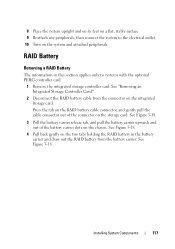
..., stable surface. 9 Reattach any peripherals, then connect the system to systems with the optional PERC controller card. 1 Remove the integrated storage controller card. RAID Battery Removing a RAID Battery The information in the battery carrier and draw out the RAID battery from the connector on the storage card. See Figure 3-18. Installing System Components 117 Press...
..., stable surface. 9 Reattach any peripherals, then connect the system to systems with the optional PERC controller card. 1 Remove the integrated storage controller card. RAID Battery Removing a RAID Battery The information in the battery carrier and draw out the RAID battery from the connector on the storage card. See Figure 3-18. Installing System Components 117 Press...
Hardware Owner's Manual
Page 118
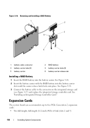
... 1 2 3 6 5 4 1 battery cable connector 3 battery carrier tabs (2) 5 battery carrier 2 RAID battery 4 battery carrier slots (2) 6 battery carrier release tab Installing a RAID Battery 1 Insert the RAID battery into place. See Figure 3-18. 3 Connect the battery cable to five PCIe Generation 2 expansion cards:...See Figure 3-18. 2 Insert the battery carrier with the RAID battery into the battery carrier slots until the carrier release latch locks into the battery carrier. See "Installing an Integrated Storage Controller Card." Expansion Cards The system board can accommodate up to ...
... 1 2 3 6 5 4 1 battery cable connector 3 battery carrier tabs (2) 5 battery carrier 2 RAID battery 4 battery carrier slots (2) 6 battery carrier release tab Installing a RAID Battery 1 Insert the RAID battery into place. See Figure 3-18. 3 Connect the battery cable to five PCIe Generation 2 expansion cards:...See Figure 3-18. 2 Insert the battery carrier with the RAID battery into the battery carrier slots until the carrier release latch locks into the battery carrier. See "Installing an Integrated Storage Controller Card." Expansion Cards The system board can accommodate up to ...


