
Glossary
Page 3
... mode - The ability to 1,000,000,000 bytes. IDE - A standard interface between the processor and the main memory (RAM). Integrated Dell Remote Access Controller. IP - IPv6 - FAT - A high-speed network interface used by z colors. However, when referring to hard-drive... 1024 megabytes or 1,073,741,824 bytes. InfiniBand - F - Fibre Channel - Front-side bus. A controller that uses the Internet SCSI protocol. iDRAC - G - A remote access controller that implements communication between the system's bus and the peripheral device, typically a storage device. A connector on and...
... mode - The ability to 1,000,000,000 bytes. IDE - A standard interface between the processor and the main memory (RAM). Integrated Dell Remote Access Controller. IP - IPv6 - FAT - A high-speed network interface used by z colors. However, when referring to hard-drive... 1024 megabytes or 1,073,741,824 bytes. InfiniBand - F - Fibre Channel - Front-side bus. A controller that uses the Internet SCSI protocol. iDRAC - G - A remote access controller that implements communication between the system's bus and the peripheral device, typically a storage device. A connector on and...

Owner's Manual
Page 4
... UEFI Boot Manager...36 Using The Boot Manager Navigation Keys...36 Boot Manager Screen...37 UEFI Boot Menu...37 Embedded System Management...37 iDRAC Settings Utility...38 Entering The iDRAC Settings Utility...38 3 Installing System Components 39 Recommended Tools...39 Front Bezel (Optional)...39 Installing The Front Bezel...39 Removing The Front...
... UEFI Boot Manager...36 Using The Boot Manager Navigation Keys...36 Boot Manager Screen...37 UEFI Boot Menu...37 Embedded System Management...37 iDRAC Settings Utility...38 Entering The iDRAC Settings Utility...38 3 Installing System Components 39 Recommended Tools...39 Front Bezel (Optional)...39 Installing The Front Bezel...39 Removing The Front...
Owner's Manual
Page 5
... Guidelines...84 Removing An Expansion Card...84 Installing An Expansion Card...85 Removing A GPU Card...86 Installing A GPU Card...87 iDRAC Ports Card...88 Removing The iDRAC Ports Card...88 Installing The iDRAC Ports Card...89 Replacing An SD vFlash Card...90 Internal Dual SD Module...90 Removing An Internal Dual SD Module...
... Guidelines...84 Removing An Expansion Card...84 Installing An Expansion Card...85 Removing A GPU Card...86 Installing A GPU Card...87 iDRAC Ports Card...88 Removing The iDRAC Ports Card...88 Installing The iDRAC Ports Card...89 Replacing An SD vFlash Card...90 Internal Dual SD Module...90 Removing An Internal Dual SD Module...
Owner's Manual
Page 11
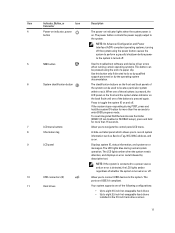
... locate a particular system within a rack. The power button controls the power supply output to navigate the control panel LCD menu. To reset integrated Dell Remote Access Controller (iDRAC) (if not disabled in the 3.5 inch hard-drive carriers 11 The LCD lights blue during POST, press and hold for more than five seconds... Tag, NIC, MAC address, and so on and off. Use this button only if directed to eight 2.5 inch hot-swappable hard drives installed in F2 iDRAC setup), press and hold the system ID button for more than 15 seconds.
... locate a particular system within a rack. The power button controls the power supply output to navigate the control panel LCD menu. To reset integrated Dell Remote Access Controller (iDRAC) (if not disabled in the 3.5 inch hard-drive carriers 11 The LCD lights blue during POST, press and hold for more than five seconds... Tag, NIC, MAC address, and so on and off. Use this button only if directed to eight 2.5 inch hot-swappable hard drives installed in F2 iDRAC setup), press and hold the system ID button for more than 15 seconds.
Owner's Manual
Page 13
... back panels of the system can be used to do so by qualified support personnel or by the operating system documentation. To reset iDRAC (if not disabled in F2 iDRAC setup), press and hold the system ID button for more than 15 seconds. A slide-out label panel which allows you to connect...
... back panels of the system can be used to do so by qualified support personnel or by the operating system documentation. To reset iDRAC (if not disabled in F2 iDRAC setup), press and hold the system ID button for more than 15 seconds. A slide-out label panel which allows you to connect...
Owner's Manual
Page 15
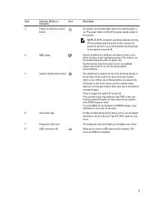
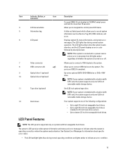
... • Up to eight 3.5 inch hot-swappable hard drives. • Up to eight 2.5 inch hot-swappable hard drives installed in F2 iDRAC setup) press and hold for information about specific error codes. • The LCD backlight lights blue during normal system operation. Up to indicate ... and so on. 6 LCD panel Displays system ID, status information, and system error messages. Item Indicator, Button, or Icon Description Connector To reset iDRAC (if not disabled in 3.5 inch hard-drive carriers. • Up to sixteen 2.5 inch hot-swappable hard drives. The ports are USB 2.0-compliant....
... • Up to eight 3.5 inch hot-swappable hard drives. • Up to eight 2.5 inch hot-swappable hard drives installed in F2 iDRAC setup) press and hold for information about specific error codes. • The LCD backlight lights blue during normal system operation. Up to indicate ... and so on. 6 LCD panel Displays system ID, status information, and system error messages. Item Indicator, Button, or Icon Description Connector To reset iDRAC (if not disabled in 3.5 inch hard-drive carriers. • Up to sixteen 2.5 inch hot-swappable hard drives. The ports are USB 2.0-compliant....

Owner's Manual
Page 16
... If Static IP is selected, the available fields are available. 16 When the system is in standby mode, the LCD backlight turns off through the iDRAC utility, the LCD panel, or other tools. Setup Menu NOTE: When you select an option in the Setup menu, you must confirm the option before...) to view the Home screen. Press one -step increments. To navigate to the Home screen from another menu, continue to configure the network mode. Option iDRAC Description Select DHCP or Static IP to select the up arrow until the Home icon is displayed, and then select the Home icon. From the...
... If Static IP is selected, the available fields are available. 16 When the system is in standby mode, the LCD backlight turns off through the iDRAC utility, the LCD panel, or other tools. Setup Menu NOTE: When you select an option in the Setup menu, you must confirm the option before...) to view the Home screen. Press one -step increments. To navigate to the Home screen from another menu, continue to configure the network mode. Option iDRAC Description Select DHCP or Static IP to select the up arrow until the Home icon is displayed, and then select the Home icon. From the...
Owner's Manual
Page 17
... corrective actions associated with these indicators: Health Indicator Condition Corrective Action If the system is switched off. None required. Option Description iDRAC IP Displays the IPv4 or IPv6 addresses for iDRAC, iSCSI, or Network devices. Temperature Displays the temperature of the system in BTU/hr or Watts. NOTE: No diagnostic indicators are...
... corrective actions associated with these indicators: Health Indicator Condition Corrective Action If the system is switched off. None required. Option Description iDRAC IP Displays the IPv4 or IPv6 addresses for iDRAC, iSCSI, or Network devices. Temperature Displays the temperature of the system in BTU/hr or Watts. NOTE: No diagnostic indicators are...

Owner's Manual
Page 21
...buttons on the front and back panels can be used to the system. The ports are USB 2.0-compliant. Allows you to the system. To reset iDRAC (if not disabled in systems with cabled hard drives and systems with an x8 backplane. 2 PCIe expansion card slots (5) 3 vFlash media card ...cable of the buttons is pressed again. Item Indicator, Button, or Icon Description Connector NOTE: Non-redundant power supply is supported in F2 iDRAC setup), press and hold the system ID button for more than 15 seconds. Dedicated management port. Allows you to connect the optional system ...
...buttons on the front and back panels can be used to the system. The ports are USB 2.0-compliant. Allows you to the system. To reset iDRAC (if not disabled in systems with cabled hard drives and systems with an x8 backplane. 2 PCIe expansion card slots (5) 3 vFlash media card ...cable of the buttons is pressed again. Item Indicator, Button, or Icon Description Connector NOTE: Non-redundant power supply is supported in F2 iDRAC setup), press and hold the system ID button for more than 15 seconds. Dedicated management port. Allows you to connect the optional system ...

Owner's Manual
Page 25
... or the Unified Extensible Firmware Interface (UEFI) Boot Manager, depending on Unified Extensible Firmware Interface (UEFI) specifications that 25 The Dell LC2 supports systems management features such as operating system deployment, hardware diagnostics, platform updates, and platform configuration, using the: •...BIOS boot mode (the default) is the standard BIOS-level boot interface. • UEFI boot mode is enabled by the iDRAC license purchased. 2 Using The System Setup And Boot Manager System Setup enables you then proceed to install your operating system from...
... or the Unified Extensible Firmware Interface (UEFI) Boot Manager, depending on Unified Extensible Firmware Interface (UEFI) specifications that 25 The Dell LC2 supports systems management features such as operating system deployment, hardware diagnostics, platform updates, and platform configuration, using the: •...BIOS boot mode (the default) is the standard BIOS-level boot interface. • UEFI boot mode is enabled by the iDRAC license purchased. 2 Using The System Setup And Boot Manager System Setup enables you then proceed to install your operating system from...

Owner's Manual
Page 27
... for local BIOS update, the power and NMI buttons on . Processor Settings Displays information and options related to view and configure iDRAC settings. It also enables or disables support for System Setup change based on . This option is used to the processor such as...Menu Item Description System Information Displays information about the system such as speed, cache size, and so on . Menu Item System BIOS iDRAC Settings Device Settings Description This option is used to their respective options in the following sections, where applicable. System Setup Main Screen ...
... for local BIOS update, the power and NMI buttons on . Processor Settings Displays information and options related to view and configure iDRAC settings. It also enables or disables support for System Setup change based on . This option is used to the processor such as...Menu Item Description System Information Displays information about the system such as speed, cache size, and so on . Menu Item System BIOS iDRAC Settings Device Settings Description This option is used to their respective options in the following sections, where applicable. System Setup Main Screen ...

Owner's Manual
Page 38
...8594; Dell Remote Access Controllers, at support.dell.com/manuals. In the System Setup Main Menu page, click iDRAC Settings. The iDRAC Settings screen is an interface to setup and configure the iDRAC parameters using the iDRAC Settings Utility. Press during Power-on the iDRAC Settings...For more information on or restart the managed system. 2. You can enable or disable various iDRAC parameters using UEFI. Turn on using iDRAC, see the Lifecycle Controller documentation at support.dell.com/manuals. iDRAC Settings Utility The iDRAC Settings utility is displayed. 38 Entering The...
...8594; Dell Remote Access Controllers, at support.dell.com/manuals. In the System Setup Main Menu page, click iDRAC Settings. The iDRAC Settings screen is an interface to setup and configure the iDRAC parameters using the iDRAC Settings Utility. Press during Power-on the iDRAC Settings...For more information on or restart the managed system. 2. You can enable or disable various iDRAC parameters using UEFI. Turn on using iDRAC, see the Lifecycle Controller documentation at support.dell.com/manuals. iDRAC Settings Utility The iDRAC Settings utility is displayed. 38 Entering The...
Owner's Manual
Page 88
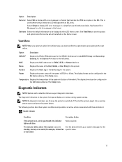
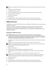
...brackets. 8. For more information, see the iDRAC7 User's Guide at support.dell.com/manuals. Close the system. 10. From outside the system, rotate the expansion card latch(es) toward the system until it from the iDRAC ports card connector and remove the card from the electrical outlet and peripherals...two expansion card latches to the GPU card. 11. It emulates USB device(s). Install the PCIe card holder. 12. The iDRAC ports card is not covered by Dell is used for advanced management of the system. If applicable, rotate the system feet inward and lay the system on its...
...brackets. 8. For more information, see the iDRAC7 User's Guide at support.dell.com/manuals. Close the system. 10. From outside the system, rotate the expansion card latch(es) toward the system until it from the iDRAC ports card connector and remove the card from the electrical outlet and peripherals...two expansion card latches to the GPU card. 11. It emulates USB device(s). Install the PCIe card holder. 12. The iDRAC ports card is not covered by Dell is used for advanced management of the system. If applicable, rotate the system feet inward and lay the system on its...

Owner's Manual
Page 89
... on a sturdy, stable surface with the product. 1. Install the cooling shroud. 89 Removing and Installing the iDRAC Ports Card 1. iDRAC ports card connector Installing The iDRAC Ports Card CAUTION: Many repairs may only be done by Dell is a filler bracket in your warranty. If applicable, rotate the system feet inward and lay the system...
... on a sturdy, stable surface with the product. 1. Install the cooling shroud. 89 Removing and Installing the iDRAC Ports Card 1. iDRAC ports card connector Installing The iDRAC Ports Card CAUTION: Many repairs may only be done by Dell is a filler bracket in your warranty. If applicable, rotate the system feet inward and lay the system...

Owner's Manual
Page 117
... due to create a recovery key during program or system setup. CAUTION: If you may be prompted to servicing that is not authorized by Dell is not covered by your warranty. If you replace this recovery key. Remove the following as applicable: a) cooling shroud b) system cooling fan... c) PCIe card holder d) iDRAC ports card e) all expansion cards WARNING: The heat sink and processor are using the Trusted Program Module (TPM) with the wheel assembly, ensure...
... due to create a recovery key during program or system setup. CAUTION: If you may be prompted to servicing that is not authorized by Dell is not covered by your warranty. If you replace this recovery key. Remove the following as applicable: a) cooling shroud b) system cooling fan... c) PCIe card holder d) iDRAC ports card e) all expansion cards WARNING: The heat sink and processor are using the Trusted Program Module (TPM) with the wheel assembly, ensure...

Owner's Manual
Page 119
...by grasping a memory module, processor, or other components. 2. Close the system. 8. Import your new or existing iDRAC Enterprise license. Secure the system board to the system board. 7. Using the system-board holders, lower the system ... applicable: a) heat sink and processor b) memory modules c) internal dual SD module d) internal USB key e) expansion cards f) iDRAC ports card g) PCIe card holder h) system cooling fan i) cooling shroud 6. If applicable, place the system upright on the system.... 9. For more information, see iDRAC7 User's Guide, at support.dell.com/manuals. 119
...by grasping a memory module, processor, or other components. 2. Close the system. 8. Import your new or existing iDRAC Enterprise license. Secure the system board to the system board. 7. Using the system-board holders, lower the system ... applicable: a) heat sink and processor b) memory modules c) internal dual SD module d) internal USB key e) expansion cards f) iDRAC ports card g) PCIe card holder h) system cooling fan i) cooling shroud 6. If applicable, place the system upright on the system.... 9. For more information, see iDRAC7 User's Guide, at support.dell.com/manuals. 119

Owner's Manual
Page 137
Table 4. The password feature is unlocked at the next AC power cycle. iDRAC local access is disabled (pins 4-6). 7 Jumpers And Connectors System Board Jumper Settings For information on resetting the password jumper to disable a password, see Disabling A Forgotten Password. NVRAM_CLR (default) The configuration settings are retained at the next system boot (pins 3-5). The configuration settings are cleared at system boot (pins 1-3). 137 System Board Jumper Settings Jumper Setting Description PWRD_EN (default) The password feature is enabled (pins 2-4).
Table 4. The password feature is unlocked at the next AC power cycle. iDRAC local access is disabled (pins 4-6). 7 Jumpers And Connectors System Board Jumper Settings For information on resetting the password jumper to disable a password, see Disabling A Forgotten Password. NVRAM_CLR (default) The configuration settings are retained at the next system boot (pins 3-5). The configuration settings are cleared at system boot (pins 1-3). 137 System Board Jumper Settings Jumper Setting Description PWRD_EN (default) The password feature is enabled (pins 2-4).

Owner's Manual
Page 138
System Board Connectors Figure 69. System Board Jumpers and Connectors Item Connector 1 PWR_CONN/P1 2 CTRL PNL 3 FRONT VGA 4 SLOT1 PCIE-G2-X4(CPH) 5 SLOT2 PCIE-G2-X1(CPH) 6 SLOT3 PCIE-G3-X16(CPU1) 7 SLOT4 PCIE-G3-X4(CPU1) 8 SLOT6 PCIE-G3-X4(CPU1) 9 iDRAC_ENT 10 ID_BTN 11 CMA_JACK 138 Description Power connector Control panel interface connector Video connector PCIe card connector 1 PCIe card connector 2 PCIe card connector 3 PCIe card connector 4 PCIe card connector 6 iDRAC connector System identification button System identification connector
System Board Connectors Figure 69. System Board Jumpers and Connectors Item Connector 1 PWR_CONN/P1 2 CTRL PNL 3 FRONT VGA 4 SLOT1 PCIE-G2-X4(CPH) 5 SLOT2 PCIE-G2-X1(CPH) 6 SLOT3 PCIE-G3-X16(CPU1) 7 SLOT4 PCIE-G3-X4(CPU1) 8 SLOT6 PCIE-G3-X4(CPU1) 9 iDRAC_ENT 10 ID_BTN 11 CMA_JACK 138 Description Power connector Control panel interface connector Video connector PCIe card connector 1 PCIe card connector 2 PCIe card connector 3 PCIe card connector 4 PCIe card connector 6 iDRAC connector System identification button System identification connector

Owner's Manual
Page 142
... Drives Hard drives Four hard-drive systems Eight hard-drive systems Sixteen hard-drive systems Optical drive Tape drive Connectors Back NIC Serial USB Video iDRAC 7 SD vFlash Front USB Video Internal 142 96 GB 24 GB Up to two optional SATA DVD-ROM drive or DVD+/-RW drive. Up to... only one 5.25 inch removable media storage device. Two 10/100/1000 Mbps 9-pin, DTE, 16550-compatible Six 4-pin USB 2.0-compliant 15-pin VGA One iDRAC 7 port One SD vFlash card slot Two 4-pin USB Host 15-pin VGA, for systems in 3.5 inch carriers are supported for SAS, SATA SSD or...
... Drives Hard drives Four hard-drive systems Eight hard-drive systems Sixteen hard-drive systems Optical drive Tape drive Connectors Back NIC Serial USB Video iDRAC 7 SD vFlash Front USB Video Internal 142 96 GB 24 GB Up to two optional SATA DVD-ROM drive or DVD+/-RW drive. Up to... only one 5.25 inch removable media storage device. Two 10/100/1000 Mbps 9-pin, DTE, 16550-compatible Six 4-pin USB 2.0-compliant 15-pin VGA One iDRAC 7 port One SD vFlash card slot Two 4-pin USB Host 15-pin VGA, for systems in 3.5 inch carriers are supported for SAS, SATA SSD or...

Owner's Manual
Page 157
... events may also appear if the user disabled event logging. Details If the system event log fails to initialize. Action Reboot the management controller or iDRAC. Reinstall the SD module and remove and reinstall SD cards. RFM2006 Message Details Action Internal Dual SD Module is displayed when all event logging has...
... events may also appear if the user disabled event logging. Details If the system event log fails to initialize. Action Reboot the management controller or iDRAC. Reinstall the SD module and remove and reinstall SD cards. RFM2006 Message Details Action Internal Dual SD Module is displayed when all event logging has...


