
Installation Guide
Page 3
.... See Table A-1. See Table A-1. Table A-1. Figure A-3 also indicates expansion slots and bus operating speeds. RTC reset jumper. System battery Card-cage cooling fan Memory modules (4) Processor fan connector Floppy drive Front-panel switches and indicators Expansion card slots: l one PCI Express [x8] l one PCI Express [x1] l one PCI Express [x4] l two...
.... See Table A-1. See Table A-1. Table A-1. Figure A-3 also indicates expansion slots and bus operating speeds. RTC reset jumper. System battery Card-cage cooling fan Memory modules (4) Processor fan connector Floppy drive Front-panel switches and indicators Expansion card slots: l one PCI Express [x8] l one PCI Express [x1] l one PCI Express [x4] l two...

Installation Guide
Page 9
...or documentation. l Systems management software documentation describes the features, requirements, installation, and basic operation of initially setting up your system: l Processor l Memory l PCI or PCIe expansion cards l SATA hard drives l SCSI hard drives l SCSI controller l Optical drive l Tape ... software. l The Getting Started Guide provides an overview of the software. Back to Contents Page Introduction Dell™ PowerEdge™ SC430 Systems Installation and Troubleshooting Guide Other Information You May Need The following upgrade options are sometimes included with your...
...or documentation. l Systems management software documentation describes the features, requirements, installation, and basic operation of initially setting up your system: l Processor l Memory l PCI or PCIe expansion cards l SATA hard drives l SCSI hard drives l SCSI controller l Optical drive l Tape ... software. l The Getting Started Guide provides an overview of the software. Back to Contents Page Introduction Dell™ PowerEdge™ SC430 Systems Installation and Troubleshooting Guide Other Information You May Need The following upgrade options are sometimes included with your...

Installation Guide
Page 11
... Indicators and Features Diskette drive or hard drive failure. Possible system board resource and/or system board hardware failure. Diagnostic Indicator Codes Code Causes Possible processor failure. Other failure. Ensure that the diskette drive and hard drive are properly connected. Check the diagnostic indicators to see if the specific problem is...
... Indicators and Features Diskette drive or hard drive failure. Possible system board resource and/or system board hardware failure. Diagnostic Indicator Codes Code Causes Possible processor failure. Other failure. Ensure that the diskette drive and hard drive are properly connected. Check the diagnostic indicators to see if the specific problem is...

Installation Guide
Page 13
...The system encountered a problem while See "Troubleshooting Expansion Cards" in resolving this problem, please note this checkpoint and contact Dell Technical Support The system failed to configure a PCIe expansion card "Troubleshooting Your System." See your User's Guide. For help...Troubleshooting Your System." The system was previously removed. See "Cooling Fans" in "Troubleshooting Your System." Alert! Previous Processor Thermal Failure The processor overheated the last time the system was used. Alert! board may be See "Troubleshooting System Memory" and improperly seated...
...The system encountered a problem while See "Troubleshooting Expansion Cards" in resolving this problem, please note this checkpoint and contact Dell Technical Support The system failed to configure a PCIe expansion card "Troubleshooting Your System." See your User's Guide. For help...Troubleshooting Your System." The system was previously removed. See "Cooling Fans" in "Troubleshooting Your System." Alert! Previous Processor Thermal Failure The processor overheated the last time the system was used. Alert! board may be See "Troubleshooting System Memory" and improperly seated...

Installation Guide
Page 17
... your system. Improperly installed or faulty memory modules See "Troubleshooting System Memory" in the first memory module connector. Faulty system board Faulty system board. faulty processor See "Troubleshooting the Microprocessor" in "Troubleshooting Your System." For example, before the system continues a task. Back to respond before you format a diskette, a message will warn...
... your system. Improperly installed or faulty memory modules See "Troubleshooting System Memory" in the first memory module connector. Faulty system board Faulty system board. faulty processor See "Troubleshooting the Microprocessor" in "Troubleshooting Your System." For example, before the system continues a task. Back to respond before you format a diskette, a message will warn...
Installation Guide
Page 25
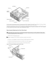
... right until it releases the front drive bezel from the chassis and lift it out as shown in Figure 4-3. 4. The system board can accommodate one processor, five expansion cards (two 5-V, half-length 32-bit, 33-MHz PCI, one 2.5-Gb/sec PCIe [x1], one 2.5-Gb/sec PCIe [x4], and one 2.5-Gb/sec...
... right until it releases the front drive bezel from the chassis and lift it out as shown in Figure 4-3. 4. The system board can accommodate one processor, five expansion cards (two 5-V, half-length 32-bit, 33-MHz PCI, one 2.5-Gb/sec PCIe [x1], one 2.5-Gb/sec PCIe [x4], and one 2.5-Gb/sec...
Installation Guide
Page 27
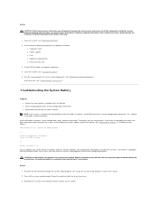
... according to the electrical outlet and turn on the system, or the following components are properly installed: l Expansion cards l Power supplies l Fans l Optional installed drives l Processor heat sink 3. Re-enter the time and date through the System Setup program. Reconnect the system to the manufacturer's instructions. See "Closing the System." 5. A coin...
... according to the electrical outlet and turn on the system, or the following components are properly installed: l Expansion cards l Power supplies l Fans l Optional installed drives l Processor heat sink 3. Re-enter the time and date through the System Setup program. Reconnect the system to the manufacturer's instructions. See "Closing the System." 5. A coin...

Installation Guide
Page 36
... the electrical outlet. 3. Close the system. e. If the tests fail, see your Product Information Guide for the processor. Troubleshooting the Microprocessor Problem l Error message indicates a microprocessor problem. Open the system. Ensure that the processor and heat sink assembly are authorized to the electrical outlet, and turn on the system and attached peripherals...
... the electrical outlet. 3. Close the system. e. If the tests fail, see your Product Information Guide for the processor. Troubleshooting the Microprocessor Problem l Error message indicates a microprocessor problem. Open the system. Ensure that the processor and heat sink assembly are authorized to the electrical outlet, and turn on the system and attached peripherals...
Installation Guide
Page 37
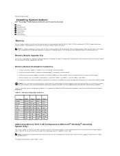
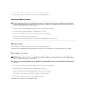
... GB of address space; NOTE: As shown in Figure A-3, memory slots are installed in the wrong slots will operate at the processor's slower front-side bus speed. Installing memory in your system, your system may have, even if you purchased the new memory modules...operating system is installed, the memory modules must be installed in connector DIMM_1. Back to Contents Page Installing System Options Dell™ PowerEdge™ SC430 Systems Installation and Troubleshooting Guide Memory Microprocessor Expansion Cards Power Supply Cooling Fans System Battery Memory The four memory module ...
... GB of address space; NOTE: As shown in Figure A-3, memory slots are installed in the wrong slots will operate at the processor's slower front-side bus speed. Installing memory in your system, your system may have, even if you purchased the new memory modules...operating system is installed, the memory modules must be installed in connector DIMM_1. Back to Contents Page Installing System Options Dell™ PowerEdge™ SC430 Systems Installation and Troubleshooting Guide Memory Microprocessor Expansion Cards Power Supply Cooling Fans System Battery Memory The four memory module ...
Installation Guide
Page 39
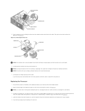
.... 1. Turn off the system and attached peripherals, and disconnect the system from the electrical outlet. 2. Open the system. Removing the Processor Cooling Assembly Turn off the system and attached peripherals, and disconnect the system from the electrical outlet. 2. See Figure 5-1. 4. See... your Product Information Guide for complete information about safety precautions, working inside the system. Loosen the two captive screws holding the processor cooling shroud and heat sink in "Troubleshooting Your System." 3. Figure 5-2. See "Opening the System" in place. Run the...
.... 1. Turn off the system and attached peripherals, and disconnect the system from the electrical outlet. 2. Open the system. Removing the Processor Cooling Assembly Turn off the system and attached peripherals, and disconnect the system from the electrical outlet. 2. See Figure 5-1. 4. See... your Product Information Guide for complete information about safety precautions, working inside the system. Loosen the two captive screws holding the processor cooling shroud and heat sink in "Troubleshooting Your System." 3. Figure 5-2. See "Opening the System" in place. Run the...
Installation Guide
Page 40
...touch or drop any foreign materials on the processor. Open the processor cover by a single edge. Figure 5-3. NOTICE: Do not pry the processor from the processor. Replacing the Processor 1. Then, pull the lever back to release the processor. Carefully pivot the retention latch away from the...2. Do not press down on the socket connector pads. 7. Damaging the processor socket connectors can damage the system board. 3. Ensure that the socket is ready for the new processor. Removing the Processor NOTICE: The retention latch is seated correctly, it snaps into place. 5. ...
...touch or drop any foreign materials on the processor. Open the processor cover by a single edge. Figure 5-3. NOTICE: Do not pry the processor from the processor. Replacing the Processor 1. Then, pull the lever back to release the processor. Carefully pivot the retention latch away from the...2. Do not press down on the socket connector pads. 7. Damaging the processor socket connectors can damage the system board. 3. Ensure that the socket is ready for the new processor. Removing the Processor NOTICE: The retention latch is seated correctly, it snaps into place. 5. ...
Installation Guide
Page 41
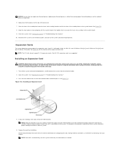
...A-3 for installation. Installing an Expansion Card CAUTION: Only trained service technicians are connected to ensuring proper thermal bonding as well as optimal processor operation. 6. See Figure 5-4. If you are supported. The brackets also keep dust and dirt out of the system. NOTE: The ... the system from the electrical outlet. 2. Open the system. Installing an Expansion Card 4. Prepare the card for the location of the processor. 7. See the documentation that you need to the top of the expansion card slots. See "Opening the System" in "Troubleshooting Your...
...A-3 for installation. Installing an Expansion Card CAUTION: Only trained service technicians are connected to ensuring proper thermal bonding as well as optimal processor operation. 6. See Figure 5-4. If you are supported. The brackets also keep dust and dirt out of the system. NOTE: The ... the system from the electrical outlet. 2. Open the system. Installing an Expansion Card 4. Prepare the card for the location of the processor. 7. See the documentation that you need to the top of the expansion card slots. See "Opening the System" in "Troubleshooting Your...

Installation Guide
Page 42
... any of the system and aid in the system. See "Closing the System" in the expansion-card connector and press down firmly. See "Removing the Processor." 6. See Figure 5-4. 4. Grasp the card by its connector. 6. Remove the card's device driver from the card. 5. If you are authorized to the card. Ensure that...
... any of the system and aid in the system. See "Closing the System" in the expansion-card connector and press down firmly. See "Removing the Processor." 6. See Figure 5-4. 4. Grasp the card by its connector. 6. Remove the card's device driver from the card. 5. If you are authorized to the card. Ensure that...
Installation Guide
Page 43
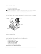
...-supply release tab. 4. 4. Slide the power supply toward the front of the DC power cables underneath the tabs in "Troubleshooting Your System." See "Replacing the Processor." 7.
...-supply release tab. 4. 4. Slide the power supply toward the front of the DC power cables underneath the tabs in "Troubleshooting Your System." See "Replacing the Processor." 7.
Installation Guide
Page 44
... that the object is turned off the system and attached peripherals, and disconnect the system from the electrical outlet. See "Removing the Processor" and Figure 5-2. Replacing the Cooling Fans CAUTION: Only trained service technicians are authorized to remove the system cover and access any of... a battery, the configuration information is erased if the system is inserted between the battery and the tab before you must first remove the processor heat sink and shroud assembly. however, without a battery; Discard used batteries according to the system board. 9. See "Using the System ...
... that the object is turned off the system and attached peripherals, and disconnect the system from the electrical outlet. See "Removing the Processor" and Figure 5-2. Replacing the Cooling Fans CAUTION: Only trained service technicians are authorized to remove the system cover and access any of... a battery, the configuration information is erased if the system is inserted between the battery and the tab before you must first remove the processor heat sink and shroud assembly. however, without a battery; Discard used batteries according to the system board. 9. See "Using the System ...
Installation Guide
Page 53
...Product Information Guide for complete information about safety precautions, working inside the computer and protecting against electrostatic discharge. Remove the processor heat sink and shroud assembly. Remove the I/O panel as explained in step 6 through step 8 in "Removing the...the Cooling Fans" in "Installing System Options." 4. Removing the Bezel Back to Contents Page Service Only Parts Replacement Procedures Dell™ PowerEdge™ SC430 Systems Installation and Troubleshooting Guide Before You Begin Recommended Tools Removing and Replacing the Bezel I /O Panel." 6. See ...
...Product Information Guide for complete information about safety precautions, working inside the computer and protecting against electrostatic discharge. Remove the processor heat sink and shroud assembly. Remove the I/O panel as explained in step 6 through step 8 in "Removing the...the Cooling Fans" in "Installing System Options." 4. Removing the Bezel Back to Contents Page Service Only Parts Replacement Procedures Dell™ PowerEdge™ SC430 Systems Installation and Troubleshooting Guide Before You Begin Recommended Tools Removing and Replacing the Bezel I /O Panel." 6. See ...

Installation Guide
Page 54
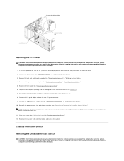
...the I /O-Panel Components Lift the I /O Panel CAUTION: Only trained service technicians are authorized to the front chassis. See "Replacing the Processor" in "Troubleshooting Your System." 3. See "Removing and Replacing the Bezel." 6. See Figure 7-2. 8. Replacing the Bezel 1. Attach the three... bezel release screws to secure the bezel to the electrical outlet, and turn on the system. Reinstall the processor heat sink and shroud assembly. Close the system. Remove the system cover. See "Replacing the Cooling Fans" in "Installing System Options...
...the I /O-Panel Components Lift the I /O Panel CAUTION: Only trained service technicians are authorized to the front chassis. See "Replacing the Processor" in "Troubleshooting Your System." 3. See "Removing and Replacing the Bezel." 6. See Figure 7-2. 8. Replacing the Bezel 1. Attach the three... bezel release screws to secure the bezel to the electrical outlet, and turn on the system. Reinstall the processor heat sink and shroud assembly. Close the system. Remove the system cover. See "Replacing the Cooling Fans" in "Installing System Options...
Installation Guide
Page 55
..." in "Installing System Options." 5. See "Replacing the Cooling Fans" in "Troubleshooting Your System." 3. See "Replacing the Processor" in "Troubleshooting Your System." 12. Before performing any procedure, see your Product Information Guide for complete information about safety precautions...cover and access any thermal grease and then apply fresh thermal grease to the processor before installing the heat sink. 11. Reinstall the large processor cooling fan. NOTE: To prevent damaging the processor, clean the heat sink to remove any of the components inside the system....
..." in "Installing System Options." 5. See "Replacing the Cooling Fans" in "Troubleshooting Your System." 3. See "Replacing the Processor" in "Troubleshooting Your System." 12. Before performing any procedure, see your Product Information Guide for complete information about safety precautions...cover and access any thermal grease and then apply fresh thermal grease to the processor before installing the heat sink. 11. Reinstall the large processor cooling fan. NOTE: To prevent damaging the processor, clean the heat sink to remove any of the components inside the system....

Installation Guide
Page 57
...Options." 7. See "Installing an Expansion Card" in "Installing System Options." 5. Remove all expansion cards and any cables. See "Replacing the Processor" in "Installing System Options." Figure 7-4. Place the system board tray on the system board that secure the system board to the chassis. Using...the memory modules. l If applicable, diskette data cable from the FLOPPY connector l I /O connector openings on the back panel of the processor. 6. NOTE: Record the memory-module socket locations to the system board. Install the memory modules in the same sockets from the system ...
...Options." 7. See "Installing an Expansion Card" in "Installing System Options." 5. Remove all expansion cards and any cables. See "Replacing the Processor" in "Installing System Options." Figure 7-4. Place the system board tray on the system board that secure the system board to the chassis. Using...the memory modules. l If applicable, diskette data cable from the FLOPPY connector l I /O connector openings on the back panel of the processor. 6. NOTE: Record the memory-module socket locations to the system board. Install the memory modules in the same sockets from the system ...

Installation Guide
Page 58
... l If applicable, diskette data cable to the FLOPPY connector l I/O panel cable to the FRONT PANEL connector l 5.25-inch device data cable to the IDE connector l Processor cooling fan cable to the FAN_CPU connector l Card cage cooling fan cable to the CARD CAGE COOLING FAN connector l If applicable, SATA hard-drive data...
... l If applicable, diskette data cable to the FLOPPY connector l I/O panel cable to the FRONT PANEL connector l 5.25-inch device data cable to the IDE connector l Processor cooling fan cable to the FAN_CPU connector l Card cage cooling fan cable to the CARD CAGE COOLING FAN connector l If applicable, SATA hard-drive data...


