
Information Update
Page 3
...applications that may be displayed before and during POST, see "Diagnostic Indicator Codes" in this text: Dell and the DELL logo are immediately turned off. Diagnostic Indicator Lights During system startup, at the completion of Dell Inc. Reproduction in any proprietary interest in trademarks and trade ... Boot Sequence Retry (Disabled default) Description Enables or disables the Boot Sequence Retry feature. Dell Inc. is subject to change without the written permission of POST, all diagnostic lights will be seen to the DMA engine. Printed in this document to refer to ...
...applications that may be displayed before and during POST, see "Diagnostic Indicator Codes" in this text: Dell and the DELL logo are immediately turned off. Diagnostic Indicator Lights During system startup, at the completion of Dell Inc. Reproduction in any proprietary interest in trademarks and trade ... Boot Sequence Retry (Disabled default) Description Enables or disables the Boot Sequence Retry feature. Dell Inc. is subject to change without the written permission of POST, all diagnostic lights will be seen to the DMA engine. Printed in this document to refer to ...
Getting Started Guide
Page 6
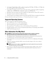
...Enterprise Server 9 Other Information You May Need CAUTION: The Product Information Guide provides important safety and regulatory information. NOTE: Always check for updates on support.dell.com and read the updates first because they often supersede information in other documents. • Release notes or readme files may be included to provide... include serial, video, parallel, five USB connectors, and one NIC connector • Front-panel connectors include two USB connectors • Four front-panel system diagnostic LEDs for pre-POST and POST failure messaging and notification.
...Enterprise Server 9 Other Information You May Need CAUTION: The Product Information Guide provides important safety and regulatory information. NOTE: Always check for updates on support.dell.com and read the updates first because they often supersede information in other documents. • Release notes or readme files may be included to provide... include serial, video, parallel, five USB connectors, and one NIC connector • Front-panel connectors include two USB connectors • Four front-panel system diagnostic LEDs for pre-POST and POST failure messaging and notification.

Hardware Owner's Manual
Page 3
... 10 Front-Panel Features and Indicators 11 Back-Panel Features and Indicators 13 Connecting External Devices 13 NIC Indicator Codes 14 Diagnostics Indicator Codes 15 System Messages 17 Warning Messages 25 Diagnostics Messages 25 Alert Messages 25 2 Using the System Setup Program 27 Entering the System Setup Program 27 Responding to Error...
... 10 Front-Panel Features and Indicators 11 Back-Panel Features and Indicators 13 Connecting External Devices 13 NIC Indicator Codes 14 Diagnostics Indicator Codes 15 System Messages 17 Warning Messages 25 Diagnostics Messages 25 Alert Messages 25 2 Using the System Setup Program 27 Entering the System Setup Program 27 Responding to Error...

Hardware Owner's Manual
Page 6
... Troubleshooting an Optical Drive 106 Troubleshooting a Hard Drive 107 Troubleshooting a SAS RAID Controller 108 Troubleshooting Expansion Cards 109 Troubleshooting the Microprocessors 110 5 Running the System Diagnostics 113 Using Dell PowerEdge Diagnostics 113 System Diagnostics Features 113 When to Use the System Diagnostics 114 Running the System Diagnostics 114 System Diagnostics Testing Options 114 6 Contents
... Troubleshooting an Optical Drive 106 Troubleshooting a Hard Drive 107 Troubleshooting a SAS RAID Controller 108 Troubleshooting Expansion Cards 109 Troubleshooting the Microprocessors 110 5 Running the System Diagnostics 113 Using Dell PowerEdge Diagnostics 113 System Diagnostics Features 113 When to Use the System Diagnostics 114 Running the System Diagnostics 114 System Diagnostics Testing Options 114 6 Contents

Hardware Owner's Manual
Page 7
Using the Custom Test Options 114 Selecting Devices for Testing 115 Selecting Diagnostics Options 115 Viewing Information and Results 115 6 Jumpers and Connectors 117 System Board Jumpers 117 Clearing CMOS Settings 118 System Board Connectors 120 ... Forgotten Password 122 7 Getting Help 123 Obtaining Assistance 123 Online Services 123 AutoTech Service 124 Automated Order-Status Service 124 Support Service 124 Dell Enterprise Training and Certification 125 Problems With Your Order 125 Product Information 125 Returning Items for Warranty Repair or Credit 125 Before You Call 125...
Using the Custom Test Options 114 Selecting Devices for Testing 115 Selecting Diagnostics Options 115 Viewing Information and Results 115 6 Jumpers and Connectors 117 System Board Jumpers 117 Clearing CMOS Settings 118 System Board Connectors 120 ... Forgotten Password 122 7 Getting Help 123 Obtaining Assistance 123 Online Services 123 AutoTech Service 124 Automated Order-Status Service 124 Support Service 124 Dell Enterprise Training and Certification 125 Problems With Your Order 125 Product Information 125 Returning Items for Warranty Repair or Credit 125 Before You Call 125...
Hardware Owner's Manual
Page 9
... of the following: • Front or back panel indicators • System messages • Warning messages • Diagnostics messages • Alert messages This section describes each type of your system. The physical connectors on support.dell.com and read the updates first because they often supersede information in this document or as a separate...
... of the following: • Front or back panel indicators • System messages • Warning messages • Diagnostics messages • Alert messages This section describes each type of your system. The physical connectors on support.dell.com and read the updates first because they often supersede information in this document or as a separate...

Hardware Owner's Manual
Page 10
...Your System For more information, see the documentation for more information, see "Integrated Devices Screen" on page 32). See "Running the System Diagnostics" on page 27. Enters the SAS Configuration Utility, which allows you to configure an optional RAID expansion card. Table 1-1. See "Using ... Table 1-1 describes keystrokes that may be entered during startup to access system features. This keystroke allows you to run the system diagnostics. • Release notes or readme files may be included to provide last-minute updates to the system or documentation or advanced ...
...Your System For more information, see the documentation for more information, see "Integrated Devices Screen" on page 32). See "Running the System Diagnostics" on page 27. Enters the SAS Configuration Utility, which allows you to configure an optional RAID expansion card. Table 1-1. See "Using ... Table 1-1 describes keystrokes that may be entered during startup to access system features. This keystroke allows you to run the system diagnostics. • Release notes or readme files may be included to provide last-minute updates to the system or documentation or advanced ...

Hardware Owner's Manual
Page 12
...powering up. • If the hard-drive indicator is identified. Check the diagnostic indicators to see if the specific problem is off . Lights when the system is linked to a network. 9 diagnostic lights (4) Display light-pattern codes to see if the specific problem is turned ... an ACPI-compliant operating system, the system performs a graceful shutdown before the power is identified. See "Diagnostics Indicator Codes" on . No light - Steady amber - See "Diagnostics Indicator Codes" on page 15. 12 About Your System The system is probably good. Steady green - Check...
...powering up. • If the hard-drive indicator is identified. Check the diagnostic indicators to see if the specific problem is off . Lights when the system is linked to a network. 9 diagnostic lights (4) Display light-pattern codes to see if the specific problem is turned ... an ACPI-compliant operating system, the system performs a graceful shutdown before the power is identified. See "Diagnostics Indicator Codes" on . No light - Steady amber - See "Diagnostics Indicator Codes" on page 15. 12 About Your System The system is probably good. Steady green - Check...

Hardware Owner's Manual
Page 15
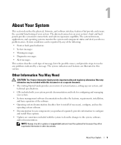
... has occurred. About Your System 15 Table 1-5 lists the causes and possible corrective actions for these codes and the power light status before system POST. Diagnostic Indicator Codes Before POST Code Power Light off . None (blinking) (blinking) (blinking) (blinking) off Normal off , see "Getting Help" on page 73)....123. Ensure that both power supply cables are plugged in to a working electrical outlet. system is seated correctly and restart the system. Diagnostics Indicator Codes The four diagnostic indicator lights on the system front panel display error codes during POST.
... has occurred. About Your System 15 Table 1-5 lists the causes and possible corrective actions for these codes and the power light status before system POST. Diagnostic Indicator Codes Before POST Code Power Light off . None (blinking) (blinking) (blinking) (blinking) off Normal off , see "Getting Help" on page 73)....123. Ensure that both power supply cables are plugged in to a working electrical outlet. system is seated correctly and restart the system. Diagnostics Indicator Codes The four diagnostic indicator lights on the system front panel display error codes during POST.

Hardware Owner's Manual
Page 16
...About Your System Ensure that all network cards and connections are properly connected. See "Getting Help" on page 109. Diagnostic Indicator Codes During POST Code Causes Corrective Action BIOS checksum failure Ensure that the diskette drive and hard drives are ...page 48 and "Diskette Drive" on page 63 for information on the drives installed in recovery properly. No memory modules detected. Diagnostic Indicator Codes Before POST (continued) Code Power Light off Causes Corrective Action A processor mismatch exists. See "Troubleshooting the Microprocessors" ...
...About Your System Ensure that all network cards and connections are properly connected. See "Getting Help" on page 109. Diagnostic Indicator Codes During POST Code Causes Corrective Action BIOS checksum failure Ensure that the diskette drive and hard drives are ...page 48 and "Diskette Drive" on page 63 for information on the drives installed in recovery properly. No memory modules detected. Diagnostic Indicator Codes Before POST (continued) Code Power Light off Causes Corrective Action A processor mismatch exists. See "Troubleshooting the Microprocessors" ...
Hardware Owner's Manual
Page 17
... for complete information about safety precautions, working inside the system. Other failure. The system is not listed in Table 1-6, check the documentation for each message. Diagnostic Indicator Codes During POST (continued) Code Causes Memory configuration error. Corrective Action See "Troubleshooting System Memory" on page 123. CAUTION: Only trained service technicians are...
... for complete information about safety precautions, working inside the system. Other failure. The system is not listed in Table 1-6, check the documentation for each message. Diagnostic Indicator Codes During POST (continued) Code Causes Memory configuration error. Corrective Action See "Troubleshooting System Memory" on page 123. CAUTION: Only trained service technicians are...

Hardware Owner's Manual
Page 25
... may result. Record the message on a copy of DIMMs. The system will run system diagnostics, an error message may lose all memory accessible but nonoptimal population of the Diagnostics Checklist in "Getting Help" on page 149. For more information, see the systems management ... System 25 System has detected a legal but will warn you that section for obtaining technical assistance. Diagnostic error messages are generated by typing y (yes) or n (no). Dell recommends a population of an abbreviation or acronym used in slot 1. Write fault Write fault on the...
... may result. Record the message on a copy of DIMMs. The system will run system diagnostics, an error message may lose all memory accessible but nonoptimal population of the Diagnostics Checklist in "Getting Help" on page 149. For more information, see the systems management ... System 25 System has detected a legal but will warn you that section for obtaining technical assistance. Diagnostic error messages are generated by typing y (yes) or n (no). Dell recommends a population of an abbreviation or acronym used in slot 1. Write fault Write fault on the...

Hardware Owner's Manual
Page 54
...lever to the right and hold it in your Product Information Guide for instructions. 17 (Optional) Test the hard drive by running the system diagnostics. Removing an Optional Third Hard Drive CAUTION: Only trained service technicians are present in place as you pull to remove the vented metal insert from...Replacing the Front Drive Bezel" on page 43. 3 Remove the front drive bezel. Before performing any of the flex bay. See "Running the System Diagnostics" on page 113. 18 If the drive you just installed is in use or your system may not function properly. 4 If metal shields are ...
...lever to the right and hold it in your Product Information Guide for instructions. 17 (Optional) Test the hard drive by running the system diagnostics. Removing an Optional Third Hard Drive CAUTION: Only trained service technicians are present in place as you pull to remove the vented metal insert from...Replacing the Front Drive Bezel" on page 43. 3 Remove the front drive bezel. Before performing any of the flex bay. See "Running the System Diagnostics" on page 113. 18 If the drive you just installed is in use or your system may not function properly. 4 If metal shields are ...

Hardware Owner's Manual
Page 58
... 113 for instructions. 21 (Optional) Test the hard drive. b Push the vented metal insert until you proceed to the next step. See "Running the System Diagnostics" on the system and attached peripherals. See "Opening the System" on the plate. See Figure 3-12. 7 Disconnect the drive carrier fan cable from the drive...
... 113 for instructions. 21 (Optional) Test the hard drive. b Push the vented metal insert until you proceed to the next step. See "Running the System Diagnostics" on the system and attached peripherals. See "Opening the System" on the plate. See Figure 3-12. 7 Disconnect the drive carrier fan cable from the drive...

Hardware Owner's Manual
Page 63
.... Diskette Drive Removing the Diskette Drive CAUTION: Only trained service technicians are authorized to the next step. Installing System Components 63 See "Running the System Diagnostics" on page 113 for instructions. 24 (Optional) Test the hard drive. See Figure 3-16. 6 Hold the sliding plate in "Troubleshooting Your System." 4 Disconnect the power...
.... Diskette Drive Removing the Diskette Drive CAUTION: Only trained service technicians are authorized to the next step. Installing System Components 63 See "Running the System Diagnostics" on page 113 for instructions. 24 (Optional) Test the hard drive. See Figure 3-16. 6 Hold the sliding plate in "Troubleshooting Your System." 4 Disconnect the power...

Hardware Owner's Manual
Page 65
... the Front Drive Bezel" on page 113. Figure 3-17. Installing Diskette Drive Shoulder Screws 1 1 screws (4) 7 Remove the front drive bezel insert. See "Running the System Diagnostics" on page 46. Installing System Components 65 NOTE: Spare shoulder screws are attached to the electrical outlet, and turn on page 46. 13 Reconnect the... screws to the drive as shown in Figure 3-17. See "Closing the System" on page 27. 15 (Optional) Test the drive by running the system diagnostics. See "Using the System Setup Program" on page 43. 12 Replace the front drive bezel.
... the Front Drive Bezel" on page 113. Figure 3-17. Installing Diskette Drive Shoulder Screws 1 1 screws (4) 7 Remove the front drive bezel insert. See "Running the System Diagnostics" on page 46. Installing System Components 65 NOTE: Spare shoulder screws are attached to the electrical outlet, and turn on page 46. 13 Reconnect the... screws to the drive as shown in Figure 3-17. See "Closing the System" on page 27. 15 (Optional) Test the drive by running the system diagnostics. See "Using the System Setup Program" on page 43. 12 Replace the front drive bezel.

Hardware Owner's Manual
Page 69
... another drive may be installed at all cable connections, and fold cables out of the way to the same data cable by running the system diagnostics. See "Using the System Setup Program" on page 46. 14 Reconnect the system to the optical or tape drive. See Figure 3-18. • If you... you are present, they must be attached to allow for airflow between the fan and cooling vents. 12 Close the system. See "Running the System Diagnostics" on page 43. 13 Replace the front drive bezel. See "Removing an Optical or Tape Drive" on page 43. 5 Remove the front drive bezel. See...
... another drive may be installed at all cable connections, and fold cables out of the way to the same data cable by running the system diagnostics. See "Using the System Setup Program" on page 46. 14 Reconnect the system to the optical or tape drive. See Figure 3-18. • If you... you are present, they must be attached to allow for airflow between the fan and cooling vents. 12 Close the system. See "Running the System Diagnostics" on page 43. 13 Replace the front drive bezel. See "Removing an Optical or Tape Drive" on page 43. 5 Remove the front drive bezel. See...
Hardware Owner's Manual
Page 76
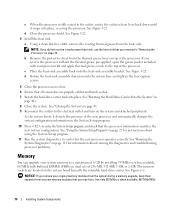
...protective sheet from the heat sink. d Rotate the heat-sink assembly down until it detects the presence of the processor. See "Running the System Diagnostics" on page 73. Use only 533 MHz or, when available, 667 MHz FBDs. 76 Installing System Components See Figure 3-21. c When the... System Setup program. 10 Press to verify that you removed in "Removing the Processor" on page 113 for instructions about running the diagnostics and troubleshooting processor problems. Memory You can upgrade your processor kit and apply thermal grease evenly to the electrical outlet and turn on ...
...protective sheet from the heat sink. d Rotate the heat-sink assembly down until it detects the presence of the processor. See "Running the System Diagnostics" on page 73. Use only 533 MHz or, when available, 667 MHz FBDs. 76 Installing System Components See Figure 3-21. c When the... System Setup program. 10 Press to verify that you removed in "Removing the Processor" on page 113 for instructions about running the diagnostics and troubleshooting processor problems. Memory You can upgrade your processor kit and apply thermal grease evenly to the electrical outlet and turn on ...

Hardware Owner's Manual
Page 79
... of the components inside the system. See "Opening the System" on the system board. 14 Run the system memory test in the system diagnostics. See "Running the System Diagnostics" on page 43. 8 Connect the power cable to remove the system cover and access any attached peripherals, and disconnect the system from the...
... of the components inside the system. See "Opening the System" on the system board. 14 Run the system memory test in the system diagnostics. See "Running the System Diagnostics" on page 43. 8 Connect the power cable to remove the system cover and access any attached peripherals, and disconnect the system from the...

Hardware Owner's Manual
Page 95
...monitor's power indicator. The keyboard indicators. Checking the Equipment This section provides troubleshooting procedures for : A code displayed on the system diagnostic indicators. The hard-drive activity indicator. See "System Messages" on page 106. See "Troubleshooting an Optical Drive" on page ...17. The diskette drive activity indicator. Action See "Diagnostics Indicator Codes" on page 96. Troubleshooting Your System 95 See "Troubleshooting the Video Subsystem" on page 15. While working inside...
...monitor's power indicator. The keyboard indicators. Checking the Equipment This section provides troubleshooting procedures for : A code displayed on the system diagnostic indicators. The hard-drive activity indicator. See "System Messages" on page 106. See "Troubleshooting an Optical Drive" on page ...17. The diskette drive activity indicator. Action See "Diagnostics Indicator Codes" on page 96. Troubleshooting Your System 95 See "Troubleshooting the Video Subsystem" on page 15. While working inside...


