
Glossary
Page 1
... SNMP agents. The modules are mounted into a chassis that contains a processor, memory, and a hard drive. A CD, diskette, or USB memory key that is located. A fast storage area that allows the processor to communicate with MIB data from the hard drive. CIM -... - Certificate authority. asset tag - ANSI - It provides mapping techniques for the peripheral devices connected to direct configuration and power management. Dell™ Glossary NOTE: For additional information on storage terminology, visit the Storage Networking Industry Association's website at www.snia.org and click on...
... SNMP agents. The modules are mounted into a chassis that contains a processor, memory, and a hard drive. A CD, diskette, or USB memory key that is located. A fast storage area that allows the processor to communicate with MIB data from the hard drive. CIM -... - Certificate authority. asset tag - ANSI - It provides mapping techniques for the peripheral devices connected to direct configuration and power management. Dell™ Glossary NOTE: For additional information on storage terminology, visit the Storage Networking Industry Association's website at www.snia.org and click on...

Glossary
Page 5
...of physical drives stores data and one or more managed systems from a central location. A portable flash memory storage device integrated with a USB connector. Millimeter(s). ms - NIC - MAC address - management station - MB - However, when referring to hard-drive capacity, the ... operating systems, integrated hardware, and software that stores basic system data. MHz - Megahertz. Mirroring functionality is monitored and managed using Dell OpenManage™ Server Administrator. A device that contains the CIM schema definition. Mb - NAS - NAS is an ASCII file that...
...of physical drives stores data and one or more managed systems from a central location. A portable flash memory storage device integrated with a USB connector. Millimeter(s). ms - NIC - MAC address - management station - MB - However, when referring to hard-drive capacity, the ... operating systems, integrated hardware, and software that stores basic system data. MHz - Megahertz. Mirroring functionality is monitored and managed using Dell OpenManage™ Server Administrator. A device that contains the CIM schema definition. Mb - NAS - NAS is an ASCII file that...

Glossary
Page 8
...of the space on each end of a SCSI cable) must be configured for peripherals, and various ROM chips. termination - TOE - UPS - USB - USB memory key - The amount of space used by setting features such as the last device at each disk. Super video graphics array. system configuration ... disable the termination on these devices by changing jumper or switch settings on a network hub or switch used . Uninterruptible power supply. USB devices can be connected and disconnected while the system is installed and how the system should be terminated to other hubs or switches without...
...of the space on each end of a SCSI cable) must be configured for peripherals, and various ROM chips. termination - TOE - UPS - USB - USB memory key - The amount of space used by setting features such as the last device at each disk. Super video graphics array. system configuration ... disable the termination on these devices by changing jumper or switch settings on a network hub or switch used . Uninterruptible power supply. USB devices can be connected and disconnected while the system is installed and how the system should be terminated to other hubs or switches without...
Glossary
Page 15
TCP/IP U-DIMM DDR3 UPS USB USB USB USB USB V VAC VDC VGA VGA 和 SVGA W WH WMI - Windows Management Instrumentation 提供 CIM ZIF CPU I/O 9 USB 15 SNMP SVGA VGA 和 SVGA TCP/IP Internet 协议。 TOE -
TCP/IP U-DIMM DDR3 UPS USB USB USB USB USB V VAC VDC VGA VGA 和 SVGA W WH WMI - Windows Management Instrumentation 提供 CIM ZIF CPU I/O 9 USB 15 SNMP SVGA VGA 和 SVGA TCP/IP Internet 协议。 TOE -

Glossary
Page 48
... alternating current VDC - Video graphics array VGA と SVGA W - Watt WH - Simple Network Management Protocol SVGA - Transmission Control Protocol/Internet Protocol TOE - Uninterruptible power supply USB - Volt direct current VGA - SMART - Super video graphics array VGA と SVGA TCP/IP - Zero insertion force 48 Self-Monitoring Analysis and Reporting Technology BIOS...
... alternating current VDC - Video graphics array VGA と SVGA W - Watt WH - Simple Network Management Protocol SVGA - Transmission Control Protocol/Internet Protocol TOE - Uninterruptible power supply USB - Volt direct current VGA - SMART - Super video graphics array VGA と SVGA TCP/IP - Zero insertion force 48 Self-Monitoring Analysis and Reporting Technology BIOS...

Glossary
Page 58
... management station managed system) 은 Dell OpenManage™ Server Administrator x x y x z 58 SVGA Super Video Graphics Array VGA 와 SVGA TCP/IP Transmission Control Protocol/Internet Protocol TOE - TCP/IP TCP/IP Offload Engine U-DIMM DDR3 Unregistered(Unbuffered) DDR3 Memory Module UPS Uninterruptible Power Supply USB Universal Serial Bus USB USB USB USB V - 볼트 (Volt VAC...
... management station managed system) 은 Dell OpenManage™ Server Administrator x x y x z 58 SVGA Super Video Graphics Array VGA 와 SVGA TCP/IP Transmission Control Protocol/Internet Protocol TOE - TCP/IP TCP/IP Offload Engine U-DIMM DDR3 Unregistered(Unbuffered) DDR3 Memory Module UPS Uninterruptible Power Supply USB Universal Serial Bus USB USB USB USB V - 볼트 (Volt VAC...

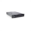
Getting Started Guide
Page 12
... 10 Getting Started With Your System Optional internal slim-line SATA DVD-ROM or DVD+/-RW Optional external USB DVD-ROM NOTE: Twelve-hard-drive systems support only an external USB DVD-ROM. Drives Hard drives Four-hard-drive systems Eight-hard-drive systems Twelve-hard-drive systems Optical ...drive Diskette drive Connectors Back NIC Serial USB Video Front Video USB Internal USB Up to four 3.5-inch, cabled SAS, SATA, or SSD drives Up to eight 3.5-inch or 2.5-inch, hot-swappable SAS, SATA, or...
... 10 Getting Started With Your System Optional internal slim-line SATA DVD-ROM or DVD+/-RW Optional external USB DVD-ROM NOTE: Twelve-hard-drive systems support only an external USB DVD-ROM. Drives Hard drives Four-hard-drive systems Eight-hard-drive systems Twelve-hard-drive systems Optical ...drive Diskette drive Connectors Back NIC Serial USB Video Front Video USB Internal USB Up to four 3.5-inch, cabled SAS, SATA, or SSD drives Up to eight 3.5-inch or 2.5-inch, hot-swappable SAS, SATA, or...

Hardware Owner's Manual
Page 7
... iDRAC6 Enterprise Card 134 Removing an iDRAC6 Enterprise Card 136 VFlash Media (Optional 137 Installing a VFlash Media Card 137 Removing a VFlash Media Card 137 Internal USB Memory Key 137 Processors 138 Removing a Processor 138 Installing a Processor 142 Contents 7
... iDRAC6 Enterprise Card 134 Removing an iDRAC6 Enterprise Card 136 VFlash Media (Optional 137 Installing a VFlash Media Card 137 Removing a VFlash Media Card 137 Internal USB Memory Key 137 Processors 138 Removing a Processor 138 Installing a Processor 142 Contents 7
Hardware Owner's Manual
Page 9
...Safety First-For You and Your System 169 Troubleshooting System Startup Failure 169 Troubleshooting External Connections 169 Troubleshooting the Video Subsystem 170 Troubleshooting a USB Device 170 Troubleshooting a Serial I/O Device 171 Troubleshooting a NIC 171 Troubleshooting a Wet System 172 Troubleshooting a Damaged System 174 Troubleshooting the... 175 Troubleshooting System Cooling Problems 176 Troubleshooting a Fan 176 Troubleshooting System Memory 177 Troubleshooting an Internal USB Key 179 Troubleshooting an Optical Drive 180 Troubleshooting a Hard Drive 181 Contents 9
...Safety First-For You and Your System 169 Troubleshooting System Startup Failure 169 Troubleshooting External Connections 169 Troubleshooting the Video Subsystem 170 Troubleshooting a USB Device 170 Troubleshooting a Serial I/O Device 171 Troubleshooting a NIC 171 Troubleshooting a Wet System 172 Troubleshooting a Damaged System 174 Troubleshooting the... 175 Troubleshooting System Cooling Problems 176 Troubleshooting a Fan 176 Troubleshooting System Memory 177 Troubleshooting an Internal USB Key 179 Troubleshooting an Optical Drive 180 Troubleshooting a Hard Drive 181 Contents 9

Hardware Owner's Manual
Page 16
... four 3.5-inch, cabled SAS or SATA drives. Figure 1-2. See "Diagnostic Lights (Optional)" on page 27. 16 About Your System NOTE: DVD devices are USB 2.0-compliant. Item Indicator, Button, Icon or Connector 7 USB connectors (2) 8 Hard drives Four-hard-drive systems Eight-hard-drive systems 9 System identification panel 10 Optical drive (optional) Description Connect...
... four 3.5-inch, cabled SAS or SATA drives. Figure 1-2. See "Diagnostic Lights (Optional)" on page 27. 16 About Your System NOTE: DVD devices are USB 2.0-compliant. Item Indicator, Button, Icon or Connector 7 USB connectors (2) 8 Hard drives Four-hard-drive systems Eight-hard-drive systems 9 System identification panel 10 Optical drive (optional) Description Connect...
Hardware Owner's Manual
Page 18
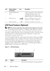
... 8 Video connector Description A slide-out panel for information on page 27. The ports are USB 2.0-compliant. The system's LCD panel provides system information and status and error messages to signify when the system is in one-step increments. The LCD ..., the LCD backlight switches off after five minutes of inactivity, and can be turned on by pressing the Select button on the LCD panel. Connect USB devices to indicate an error condition. See "LCD Status Messages (Optional)" on page 29 for system information including the Express Service tag, embedded NIC MAC...
... 8 Video connector Description A slide-out panel for information on page 27. The ports are USB 2.0-compliant. The system's LCD panel provides system information and status and error messages to signify when the system is in one-step increments. The LCD ..., the LCD backlight switches off after five minutes of inactivity, and can be turned on by pressing the Select button on the LCD panel. Connect USB devices to indicate an error condition. See "LCD Status Messages (Optional)" on page 29 for system information including the Express Service tag, embedded NIC MAC...

Hardware Owner's Manual
Page 23
...status indicator assembly through the optional cable management arm. Connect USB devices to the system. Connects four PCI Express Generation 2 expansion cards NOTE: All four slots are USB 2.0-compliant. About Your System 23 Embedded 10/100/1000 NIC... Item Indicator, Button, or Icon Connector 1 Serial connector 2 Video connector 3 iDRAC6 Enterprise port (optional) 4 VFlash media slot (optional) 5 USB connectors (2) 6 Ethernet connectors (2) 7 PCIe expansion card slots using riser card Riser 1 OR Riser 2 8 System identification connector Description Connects a ...
...status indicator assembly through the optional cable management arm. Connect USB devices to the system. Connects four PCI Express Generation 2 expansion cards NOTE: All four slots are USB 2.0-compliant. About Your System 23 Embedded 10/100/1000 NIC... Item Indicator, Button, or Icon Connector 1 Serial connector 2 Video connector 3 iDRAC6 Enterprise port (optional) 4 VFlash media slot (optional) 5 USB connectors (2) 6 Ethernet connectors (2) 7 PCIe expansion card slots using riser card Riser 1 OR Riser 2 8 System identification connector Description Connects a ...

Hardware Owner's Manual
Page 28
...Troubleshooting System error. Possible system board resource and/or system board hardware failure. Possible system resource See "Contacting Dell" on page 199. 28 About Your System Table 1-1. Possible USB failure. No memory modules detected. See "Hard Drives" on page 91 for the appropriate drive installed in ...your system. See "Troubleshooting a USB Device" on page 169 for information on the drives installed in your system. Ensure that the diskette drive and hard drive...
...Troubleshooting System error. Possible system board resource and/or system board hardware failure. Possible system resource See "Contacting Dell" on page 199. 28 About Your System Table 1-1. Possible USB failure. No memory modules detected. See "Hard Drives" on page 91 for the appropriate drive installed in ...your system. See "Troubleshooting a USB Device" on page 169 for information on the drives installed in your system. Ensure that the diskette drive and hard drive...

Hardware Owner's Manual
Page 36
.... If the problem persists, see "Getting Help" on page 199. E1A15 SAS cable B failure. If the problem persists, replace cable. E1A1D Control panel USB cable not detected. USB cable to the control panel is missing or bad. If the problem persists, see "Getting Help" on page 199. in the system. Check DIMMs...
.... If the problem persists, see "Getting Help" on page 199. E1A15 SAS cable B failure. If the problem persists, replace cable. E1A1D Control panel USB cable not detected. USB cable to the control panel is missing or bad. If the problem persists, see "Getting Help" on page 199. in the system. Check DIMMs...
Hardware Owner's Manual
Page 47
... expansion Internal_Storage card is operational. Management Shared NIC= Check the system management software or the System Setup program for each CPU should match. See "Troubleshooting a USB Device" on a dual-processor system. Invalid configuration information please run SETUP program. Invalid memory configuration on page 170.
... expansion Internal_Storage card is operational. Management Shared NIC= Check the system management software or the System Setup program for each CPU should match. See "Troubleshooting a USB Device" on a dual-processor system. Invalid configuration information please run SETUP program. Invalid memory configuration on page 170.

Hardware Owner's Manual
Page 48
... count exceeded. Ensure that the memory modules are installed in the system BIOS. Memory Initialization Warning: Memory size may not work because all user accessible USB ports are disabled in a valid configuration. out of manufacturing mode. See "General Memory Module Installation Guidelines" on failed keyboard connector. page 199. Message Causes ... but with less memory than is in a valid configuration. If operating locally, power cycle the system and enter system setup program to enable the USB port(s). Manufacturing mode detected System is physically available.
... count exceeded. Ensure that the memory modules are installed in the system BIOS. Memory Initialization Warning: Memory size may not work because all user accessible USB ports are disabled in a valid configuration. out of manufacturing mode. See "General Memory Module Installation Guidelines" on failed keyboard connector. page 199. Message Causes ... but with less memory than is in a valid configuration. If operating locally, power cycle the system and enter system setup program to enable the USB port(s). Manufacturing mode detected System is physically available.

Hardware Owner's Manual
Page 50
If the problem persists, see "Troubleshooting an Optical Drive" on page 180, "Troubleshooting a USB Device" on page 170, "Troubleshooting an Internal USB Key" on page 179, and "Troubleshooting a Hard Drive" on page 199. No boot sector on page 199. 50 About Your System If ...missing optical drive subsystem, hard drive, or hard drive subsystem, or no operating system on setting the order of boot devices. Use a bootable USB key, optical drive, or hard drive. PCIe Training Faulty or improperly Error: Expected installed PCIe card in System Setup program, or no bootable...
If the problem persists, see "Troubleshooting an Optical Drive" on page 180, "Troubleshooting a USB Device" on page 170, "Troubleshooting an Internal USB Key" on page 179, and "Troubleshooting a Hard Drive" on page 199. No boot sector on page 199. 50 About Your System If ...missing optical drive subsystem, hard drive, or hard drive subsystem, or no operating system on setting the order of boot devices. Use a bootable USB key, optical drive, or hard drive. PCIe Training Faulty or improperly Error: Expected installed PCIe card in System Setup program, or no bootable...

Hardware Owner's Manual
Page 51
...installed in the clear position (pins 1 and 3) and reboot the system. to the specified SATA port. Ensure that the USB the system could not find a cables, SAS/SATA backplane particular sector on page 181 for jumper location. defective. See "Troubleshooting...in your system. SATA Port x device not found The operating system cannot Replace the optical medium, read from the hard drive, USB medium, or USB optical drive, or USB device, device. See "General Memory Module Installation Guidelines" on page 184. Install the NVRAM_CLR jumper in a valid configuration. single...
...installed in the clear position (pins 1 and 3) and reboot the system. to the specified SATA port. Ensure that the USB the system could not find a cables, SAS/SATA backplane particular sector on page 181 for jumper location. defective. See "Troubleshooting...in your system. SATA Port x device not found The operating system cannot Replace the optical medium, read from the hard drive, USB medium, or USB optical drive, or USB device, device. See "General Memory Module Installation Guidelines" on page 184. Install the NVRAM_CLR jumper in a valid configuration. single...

Hardware Owner's Manual
Page 52
...the SEL to determine if single-bit or multi-bit errors were detected and replace the faulty memory module. Corrective Actions Replace the USB medium or device. See "Troubleshooting a USB Device" on page 170 or "Troubleshooting a Hard Drive" on page 114. See "Getting Help" on page 177. 52 ... added or removed, this message is informative and can be populated across slots. Message Causes Sector not found Faulty hard drive, USB Seek error device, or USB medium. For sparing mode, matched sets of Memory has been added or system memory has removed or a memory changed module may...
...the SEL to determine if single-bit or multi-bit errors were detected and replace the faulty memory module. Corrective Actions Replace the USB medium or device. See "Troubleshooting a USB Device" on page 170 or "Troubleshooting a Hard Drive" on page 114. See "Getting Help" on page 177. 52 ... added or removed, this message is informative and can be populated across slots. Message Causes Sector not found Faulty hard drive, USB Seek error device, or USB medium. For sparing mode, matched sets of Memory has been added or system memory has removed or a memory changed module may...

Hardware Owner's Manual
Page 58
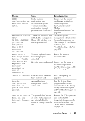
...page 179, "Troubleshooting an Optical Drive" on page 180, and "Troubleshooting a Hard Drive" on page 201. 58 About Your System Ensure that the USB, SAS backplane, or SATA cables are properly connected. NOTE: For the full name of an abbreviation or acronym used in this table, see the ..."Glossary" on page 181. Replace the USB medium or device. Message Causes Corrective Actions Write fault Write fault on selected drive Faulty USB device, USB medium, optical drive assembly, hard drive, or hard drive subsystem.
...page 179, "Troubleshooting an Optical Drive" on page 180, and "Troubleshooting a Hard Drive" on page 201. 58 About Your System Ensure that the USB, SAS backplane, or SATA cables are properly connected. NOTE: For the full name of an abbreviation or acronym used in this table, see the ..."Glossary" on page 181. Replace the USB medium or device. Message Causes Corrective Actions Write fault Write fault on selected drive Faulty USB device, USB medium, optical drive assembly, hard drive, or hard drive subsystem.


