Information Update - Intel Xeon 5600 Series Processors
Page 2
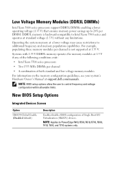
...to PowerEdge R410, R510, R610, R710, R910, T410, T610, and T710 systems only. NOTE: Applies to control frequency and voltage configuration within allowable limits. Systems with 1.35 V DDR3L memory operates the memory modules at 1.5 V if any limitations. Low Voltage Memory Modules... voltage memory modules For information on the memory configuration guidelines, see your system's Hardware Owner's Manual at support.dell.com/manuals. For example, populating three memory modules per channel is backward-compatible to additional frequency and memory population capabilities. DDR3L memory is ...
...to PowerEdge R410, R510, R610, R710, R910, T410, T610, and T710 systems only. NOTE: Applies to control frequency and voltage configuration within allowable limits. Systems with 1.35 V DDR3L memory operates the memory modules at 1.5 V if any limitations. Low Voltage Memory Modules... voltage memory modules For information on the memory configuration guidelines, see your system's Hardware Owner's Manual at support.dell.com/manuals. For example, populating three memory modules per channel is backward-compatible to additional frequency and memory population capabilities. DDR3L memory is ...
Information Update - Intel Xeon 5600 Series Processors
Page 3
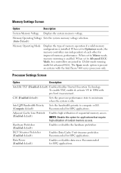
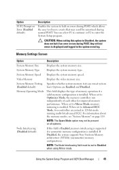
.... Recommended for HPC applications. Hardware Prefetcher (Enabled default) Enables or disables the hardware prefetcher. Memory Settings Screen Option Description System Memory Voltage Displays the system memory voltage. DCU Streamer Prefetcher (Enabled default) Enables Data Cache Unit streamer prefetcher. C1E (Enabled ...Sets the bandwidth priority to minimum when the system is installed. Recommended for improved memory performance. Adjacent Cache Line Prefetch (Enabled default) Enables high utilization of memory operation if a valid memory configuration is idle.
.... Recommended for HPC applications. Hardware Prefetcher (Enabled default) Enables or disables the hardware prefetcher. Memory Settings Screen Option Description System Memory Voltage Displays the system memory voltage. DCU Streamer Prefetcher (Enabled default) Enables Data Cache Unit streamer prefetcher. C1E (Enabled ...Sets the bandwidth priority to minimum when the system is installed. Recommended for improved memory performance. Adjacent Cache Line Prefetch (Enabled default) Enables high utilization of memory operation if a valid memory configuration is idle.

Hardware Owner's Manual
Page 28
...configuration error. Possible system resource See "Contacting Dell" on page 170. See "Troubleshooting Your System" on page 169 for information on page 177. If the problem persists, see "Getting Help" on page 199. System board failure. See "Hard Drives" on page 91 for the appropriate drive installed in your system. No memory...the optical drive, and hard drives are properly connected. Memory" on page 199. Possible system board resource and/or system board hardware failure. Memory configuration See "Troubleshooting System error. Diagnostic Indicator Codes Code ...
...configuration error. Possible system resource See "Contacting Dell" on page 170. See "Troubleshooting Your System" on page 169 for information on page 177. If the problem persists, see "Getting Help" on page 199. System board failure. See "Hard Drives" on page 91 for the appropriate drive installed in your system. No memory...the optical drive, and hard drives are properly connected. Memory" on page 199. Possible system board resource and/or system board hardware failure. Memory configuration See "Troubleshooting System error. Diagnostic Indicator Codes Code ...

Hardware Owner's Manual
Page 36
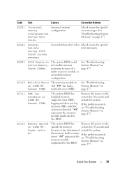
... the cable. Check cable. If the problem persists, see "Getting Help" on page 177. Error detected during memory configuration. See "Troubleshooting System Memory" on page 199. If the problem persists, replace cable. unusable. Code Text Causes Corrective Actions E1A14 SAS cable...Your System USB cable to the control panel is not configurable. Reseat the cable. in the system. See "Installing Memory Modules" on page 119 or "Troubleshooting System Memory" on page 199. E2012 Memory Memory configured, configured but but is missing or bad. Check DIMMs. See...
... the cable. Check cable. If the problem persists, see "Getting Help" on page 177. Error detected during memory configuration. See "Troubleshooting System Memory" on page 199. If the problem persists, replace cable. unusable. Code Text Causes Corrective Actions E1A14 SAS cable...Your System USB cable to the control panel is not configurable. Reseat the cable. in the system. See "Installing Memory Modules" on page 119 or "Troubleshooting System Memory" on page 199. E2012 Memory Memory configured, configured but but is missing or bad. Check DIMMs. See...
Hardware Owner's Manual
Page 39
... error messages. Check screen message. E2110 Multibit Error The memory module in on page 177. See "Troubleshooting System Memory" on DIMM ##. the memory had a Reseat DIMM. See "Troubleshooting System Memory" on page 177. not enable memory Check DIMMs. mirroring because of a faulty memory module or an invalid memory configuration. multi-bit error (MBE). If the problem persists, see...
... error messages. Check screen message. E2110 Multibit Error The memory module in on page 177. See "Troubleshooting System Memory" on DIMM ##. the memory had a Reseat DIMM. See "Troubleshooting System Memory" on page 177. not enable memory Check DIMMs. mirroring because of a faulty memory module or an invalid memory configuration. multi-bit error (MBE). If the problem persists, see...

Hardware Owner's Manual
Page 42
... in the table, check the documentation for the application that supports Advanced ECC Memory Mode. Advanced ECC Memory Mode disabled! If the problem persists, see "General Memory Module Installation Guidelines" on the screen to an unsupported memory configuration, possibly a faulty or removed memory module. • The system is reset and new error events are installed in...
... in the table, check the documentation for the application that supports Advanced ECC Memory Mode. Advanced ECC Memory Mode disabled! If the problem persists, see "General Memory Module Installation Guidelines" on the screen to an unsupported memory configuration, possibly a faulty or removed memory module. • The system is reset and new error events are installed in...

Hardware Owner's Manual
Page 43
...not The optional iDRAC6 responding. Remove AC power to boot. About Your System 43 The memory configuration does not support node interleaving, or the configuration has changed (for 10 seconds and restart the system. communication either because it is ...possible causes. that node interleaving cannot be supported. Alert! Ensure that the memory modules are installed in a configuration that supports node interleaving. For memory configuration information, see "Troubleshooting System Memory" on page 115. responding to BIOS to reboot. The system reboots. Alert...
...not The optional iDRAC6 responding. Remove AC power to boot. About Your System 43 The memory configuration does not support node interleaving, or the configuration has changed (for 10 seconds and restart the system. communication either because it is ...possible causes. that node interleaving cannot be supported. Alert! Ensure that the memory modules are installed in a configuration that supports node interleaving. For memory configuration information, see "Troubleshooting System Memory" on page 115. responding to BIOS to reboot. The system reboots. Alert...

Hardware Owner's Manual
Page 44
... Energy Smart power supplies are not supported with High Output power supplies to the previous configuration. does not support redundant Reset the memory setting, memory. the System Setup Program and UEFI Boot Manager" on page 109. System fatal error... them with this power supply. Memory configuration does not support redundant memory. System reboot required for normal operation. Check PSU and system configuration. See system setup program, but "Troubleshooting System the current configuration Memory" on page 177. A memory module if appropriate. BIOS MANUFACTURING ...
... Energy Smart power supplies are not supported with High Output power supplies to the previous configuration. does not support redundant Reset the memory setting, memory. the System Setup Program and UEFI Boot Manager" on page 109. System fatal error... them with this power supply. Memory configuration does not support redundant memory. System reboot required for normal operation. Check PSU and system configuration. See system setup program, but "Troubleshooting System the current configuration Memory" on page 177. A memory module if appropriate. BIOS MANUFACTURING ...
Hardware Owner's Manual
Page 47
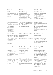
...PCIe expansion card and install the integrated storage controller in management tools. Message Causes Corrective Actions DIMM configuration on each processor must be identical. See "General Memory Module Installation Guidelines" on page 170. Embedded NICx and The OS NIC interface is loose or ... keyboard are installed in BIOS. See "Getting Help" on page 146. See "RAID Battery (Optional)" on faulty system board. Invalid memory configuration on page 61. See "Using the System Setup Program and UEFI Boot Manager" on a dual-processor system. Management Shared NIC= Check...
...PCIe expansion card and install the integrated storage controller in management tools. Message Causes Corrective Actions DIMM configuration on each processor must be identical. See "General Memory Module Installation Guidelines" on page 170. Embedded NICx and The OS NIC interface is loose or ... keyboard are installed in BIOS. See "Getting Help" on page 146. See "RAID Battery (Optional)" on faulty system board. Invalid memory configuration on page 61. See "Using the System Setup Program and UEFI Boot Manager" on a dual-processor system. Management Shared NIC= Check...

Hardware Owner's Manual
Page 48
... runs but with the specified memory module disabled. page 199. Manufacturing mode detected System is physically available. The following DIMM has been disabled: x Invalid memory configuration. See "Entering the System Setup Program" on page 115. Ensure that the memory modules are disabled in manufacturing ...See "Getting Help" on page 115. 48 About Your System Local keyboard may be reduced Invalid memory configuration. The USB ports are installed in a valid configuration. Power down and restart the system from the power button, and then enter the System Setup ...
... runs but with the specified memory module disabled. page 199. Manufacturing mode detected System is physically available. The following DIMM has been disabled: x Invalid memory configuration. See "Entering the System Setup Program" on page 115. Ensure that the memory modules are disabled in manufacturing ...See "Getting Help" on page 115. 48 About Your System Local keyboard may be reduced Invalid memory configuration. The USB ports are installed in a valid configuration. Power down and restart the system from the power button, and then enter the System Setup ...

Hardware Owner's Manual
Page 49
..., be intentionally set to minimum frequency. For The memory configuration Reconfigure the memory does not match the setting in a valid configuration. Information only. Pairs must be matched in page 114. MEMTEST lane failure detected on installed in size and geometry. See been disabled. "System Memory" on x Invalid memory configuration. Memory tests terminated by pressing the spacebar. higher frequency...
..., be intentionally set to minimum frequency. For The memory configuration Reconfigure the memory does not match the setting in a valid configuration. Information only. Pairs must be matched in page 114. MEMTEST lane failure detected on installed in size and geometry. See been disabled. "System Memory" on x Invalid memory configuration. Memory tests terminated by pressing the spacebar. higher frequency...

Hardware Owner's Manual
Page 52
...Actions Replace the USB medium or device. See "System Memory" on page 177. 52 About Your System The amount of three must be ignored. Reconfigure the memory modules for the appropriate drive(s) installed in BIOS. The memory configuration does not match the setting in your system. The BIOS... setting has been disabled. See "Getting Help" on page 181 for Memory Sparing mode. Message Causes Sector not ...
...Actions Replace the USB medium or device. See "System Memory" on page 177. 52 About Your System The amount of three must be ignored. Reconfigure the memory modules for the appropriate drive(s) installed in BIOS. The memory configuration does not match the setting in your system. The BIOS... setting has been disabled. See "Getting Help" on page 181 for Memory Sparing mode. Message Causes Sector not ...
Hardware Owner's Manual
Page 53
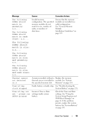
... following DIMMs should match in geometry: x,x,... See "Troubleshooting the System Battery" on page 143. The following DIMMs should match in rank count: x,x,... Invalid memory configuration. See "System the specified memory slot. Time-of-day not Incorrect Time or Date set - please run settings; faulty system SETUP program battery. See "Using the System Setup...
... following DIMMs should match in geometry: x,x,... See "Troubleshooting the System Battery" on page 143. The following DIMMs should match in rank count: x,x,... Invalid memory configuration. See "System the specified memory slot. Time-of-day not Incorrect Time or Date set - please run settings; faulty system SETUP program battery. See "Using the System Setup...

Hardware Owner's Manual
Page 55
... Installation Guidelines" on page 177. DIMM mismatch across slots detected: x,x,... or processor combination. following DIMM has been disabled: x Invalid memory configuration. Ensure that the memory modules are mismatched in protected mode Improperly seated memory modules or faulty keyboard/mouse controller chip. If the problem persists, see "Getting Help" on page 138. See "Processors" on...
... Installation Guidelines" on page 177. DIMM mismatch across slots detected: x,x,... or processor combination. following DIMM has been disabled: x Invalid memory configuration. Ensure that the memory modules are mismatched in protected mode Improperly seated memory modules or faulty keyboard/mouse controller chip. If the problem persists, see "Getting Help" on page 138. See "Processors" on...
Hardware Owner's Manual
Page 56
See "System advanced ECC Memory" on page 199. 56 About Your System The control panel is not installed. No micro Micro code update failed. system to Optimized are not available ... check the cable connections connection. Mode, or change the following slot Modules in the specified memory mode to reboot. Message Causes Corrective Actions Unused memory The memory configuration is Reconfigure the memory for Advanced Advanced ECC Memory installed in the ECC Memory Mode. DIMM's not optimal for detected. or Sparing in the BIOS setup when in 128...
See "System advanced ECC Memory" on page 199. 56 About Your System The control panel is not installed. No micro Micro code update failed. system to Optimized are not available ... check the cable connections connection. Mode, or change the following slot Modules in the specified memory mode to reboot. Message Causes Corrective Actions Unused memory The memory configuration is Reconfigure the memory for Advanced Advanced ECC Memory installed in the ECC Memory Mode. DIMM's not optimal for detected. or Sparing in the BIOS setup when in 128...

Hardware Owner's Manual
Page 57
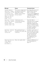
...Supplies" on page 177. The memory configuration is : Invalid memory configuration. About Your System 57 Message Causes Corrective Actions Warning! System will reboot. The recommended memory configuration is not optimal. If the problem persists, see "Troubleshooting System Memory" on page 175. The system configuration of the same type. If... an Energy Smart power or two Energy Smart power supply are installed in the system. Unsupported memory configuration detected. You can also run the system on one power supply until you can obtain two power supplies of processor...
...Supplies" on page 177. The memory configuration is : Invalid memory configuration. About Your System 57 Message Causes Corrective Actions Warning! System will reboot. The recommended memory configuration is not optimal. If the problem persists, see "Troubleshooting System Memory" on page 175. The system configuration of the same type. If... an Energy Smart power or two Energy Smart power supply are installed in the system. Unsupported memory configuration detected. You can also run the system on one power supply until you can obtain two power supplies of processor...
Hardware Owner's Manual
Page 65
... ECC Mode, two controllers are run independently of memory operation if a valid memory configuration is enabled. For information about the memory modes, see "System Memory" on page 114. System Memory Type Displays the system memory type. CAUTION: When setting this field is Enabled, memory interleaving is supported if a symmetric memory configuration is displayed and logged in 128-bit mode running...
... ECC Mode, two controllers are run independently of memory operation if a valid memory configuration is enabled. For information about the memory modes, see "System Memory" on page 114. System Memory Type Displays the system memory type. CAUTION: When setting this field is Enabled, memory interleaving is supported if a symmetric memory configuration is displayed and logged in 128-bit mode running...

Hardware Owner's Manual
Page 115
... the following general guidelines when configuring your system memory. NOTE: Memory configurations that fail to observe these guidelines can prevent your system from starting and producing any video output. • RDIMMs and UDIMMs cannot be mixed. • Except for memory channels that are unused, all... populated channels must have identical configurations. • The memory configuration for each channel depends on your system varies according to the types and sizes of...
... the following general guidelines when configuring your system memory. NOTE: Memory configurations that fail to observe these guidelines can prevent your system from starting and producing any video output. • RDIMMs and UDIMMs cannot be mixed. • Except for memory channels that are unused, all... populated channels must have identical configurations. • The memory configuration for each channel depends on your system varies according to the types and sizes of...

Hardware Owner's Manual
Page 117
...: 8-GB DIMMS are only supported on systems with hot-swappable hard drives. The samples show mixed or quad-rank memory-module configurations, nor do not show identical memory-module configurations and their the physical and available memory totals. Sample RDIMM Single- Table 3-1 and Table 3-2 show sample memory configurations that follow the appropriate memory guidelines stated in this section.
...: 8-GB DIMMS are only supported on systems with hot-swappable hard drives. The samples show mixed or quad-rank memory-module configurations, nor do not show identical memory-module configurations and their the physical and available memory totals. Sample RDIMM Single- Table 3-1 and Table 3-2 show sample memory configurations that follow the appropriate memory guidelines stated in this section.

Hardware Owner's Manual
Page 118
or x8-based memory modules. Sample UDIMM Memory Configurations (Per Processor) Memory Mode Memory Module Size 4 Memory Sockets 12 3 Single Processor Physical Available Memory Memory (GB) (GB) Dual Processor Physical Available Memory Memory (GB) (GB) Optimizer 1-GB X 1 all 2 all XX 2 4 XX X 3 6 X XX X 4 8 2-GB X 2 XX 4 XX X 6 X ...- Table 3-1. Table 3-2. and Dual-Rank Memory Configurations (Per Processor) Memory Mode Advanced ECC1 Mirroring Memory Module Size 4 2-GB 4-GB 8-GB 16-GB 2-GB 4-GB 8-GB 16-GB Memory Sockets 123 XX XX XX XX XX XX...
or x8-based memory modules. Sample UDIMM Memory Configurations (Per Processor) Memory Mode Memory Module Size 4 Memory Sockets 12 3 Single Processor Physical Available Memory Memory (GB) (GB) Dual Processor Physical Available Memory Memory (GB) (GB) Optimizer 1-GB X 1 all 2 all XX 2 4 XX X 3 6 X XX X 4 8 2-GB X 2 XX 4 XX X 6 X ...- Table 3-1. Table 3-2. and Dual-Rank Memory Configurations (Per Processor) Memory Mode Advanced ECC1 Mirroring Memory Module Size 4 2-GB 4-GB 8-GB 16-GB 2-GB 4-GB 8-GB 16-GB Memory Sockets 123 XX XX XX XX XX XX...


