Glossary
Page 4
... circuitry in a board. Small blocks on motherboard. K - Kilo-; 1000. KB - Kilobit(s) per second. Kilogram(s); 1000 grams. kHz - Liquid crystal display. Light-emitting diode. local bus - m - mA - IPX - Two devices can be designed to the LAN. Kb - Kilobyte(s); 1024 bytes. KVM refers to the...the pins. KBps - Interrupt request. Internet SCSI (see SCSI). A LAN is passed through it. iSCSI - LAN - An electronic device that lights up when a current is usually confined to the same building or a few nearby buildings, with all equipment linked by an IRQ line to ...
... circuitry in a board. Small blocks on motherboard. K - Kilo-; 1000. KB - Kilobit(s) per second. Kilogram(s); 1000 grams. kHz - Liquid crystal display. Light-emitting diode. local bus - m - mA - IPX - Two devices can be designed to the LAN. Kb - Kilobyte(s); 1024 bytes. KVM refers to the...the pins. KBps - Interrupt request. Internet SCSI (see SCSI). A LAN is passed through it. iSCSI - LAN - An electronic device that lights up when a current is usually confined to the same building or a few nearby buildings, with all equipment linked by an IRQ line to ...
Glossary
Page 45
InfiniBand IP - Kilo 1000 Kb - Kilohertz KVM - Liquid crystal display LED - LAN on motherboard。 LVD - Kilobyte 1 KB = 1024 Kbps - Meter mA - Light-emitting diode LGA - Kilobits per second kg - Local area network LAN LAN LCD - Internet package exchange IRQ - Kilobytes per second KBps - Internet Protocol IPv6 - Internet ...
InfiniBand IP - Kilo 1000 Kb - Kilohertz KVM - Liquid crystal display LED - LAN on motherboard。 LVD - Kilobyte 1 KB = 1024 Kbps - Meter mA - Light-emitting diode LGA - Kilobits per second kg - Local area network LAN LAN LCD - Internet package exchange IRQ - Kilobytes per second KBps - Internet Protocol IPv6 - Internet ...

Getting Started Guide
Page 7
The power indicators should light. Getting Started With Your System 5 Turning On the System Press the power button on the system and the monitor. Securing the Power Cable(s) Bend the system power cable into a grounded electrical outlet or a separate power source such as shown in the illustration and secure the cable to the bracket using the provided strap. Plug the other end of the power cable into a loop as an uninterrupted power supply (UPS) or a power distribution unit (PDU).
The power indicators should light. Getting Started With Your System 5 Turning On the System Press the power button on the system and the monitor. Securing the Power Cable(s) Bend the system power cable into a grounded electrical outlet or a separate power source such as shown in the illustration and secure the cable to the bracket using the provided strap. Plug the other end of the power cable into a loop as an uninterrupted power supply (UPS) or a power distribution unit (PDU).

Hardware Owner's Manual
Page 3
Contents 1 About Your System 13 Accessing System Features During Startup 13 Front-Panel Features and Indicators 14 LCD Panel Features (Optional 18 Home Screen 19 Setup Menu 20 View Menu 20 Hard-Drive Indicator Patterns 21 Back-Panel Features and Indicators 22 Guidelines for Connecting Optional External Devices 25 NIC Indicator Codes 25 Power Indicator Codes 26 Diagnostic Lights (Optional 27 LCD Status Messages (Optional 29 Solving Problems Described by LCD Status Messages 41 Removing LCD Status Messages 41 System Messages 42 Warning Messages 59 Contents 3
Contents 1 About Your System 13 Accessing System Features During Startup 13 Front-Panel Features and Indicators 14 LCD Panel Features (Optional 18 Home Screen 19 Setup Menu 20 View Menu 20 Hard-Drive Indicator Patterns 21 Back-Panel Features and Indicators 22 Guidelines for Connecting Optional External Devices 25 NIC Indicator Codes 25 Power Indicator Codes 26 Diagnostic Lights (Optional 27 LCD Status Messages (Optional 29 Solving Problems Described by LCD Status Messages 41 Removing LCD Status Messages 41 System Messages 42 Warning Messages 59 Contents 3

Hardware Owner's Manual
Page 14
... Features and Indicators (Eight-Hard-Drive System) 1 2 3 456 7 8 9 10 Item Indicator, Button, Icon or Connector 1 Power-on indicator/ power button Description The power-on indicator lights when the system power is not accessible. NOTE: On ACPI-compliant operating systems, turning off . NOTE: To force an ungraceful shutdown, press and hold the...
... Features and Indicators (Eight-Hard-Drive System) 1 2 3 456 7 8 9 10 Item Indicator, Button, Icon or Connector 1 Power-on indicator/ power button Description The power-on indicator lights when the system power is not accessible. NOTE: On ACPI-compliant operating systems, turning off . NOTE: To force an ungraceful shutdown, press and hold the...
Hardware Owner's Manual
Page 15
... back panels can be used to do so by qualified support personnel or by descriptive text. The LCD lights blue during system startup. The LED panel has four diagnostic indicator lights that display error codes during normal system operation. Use this button only if directed to locate a particular...: Systems with cabled hard drives support an LED panel instead of a paper clip. See "Diagnostic Lights (Optional)" on . Allow you to AC power and an error has been detected, the LCD lights amber regardless of the buttons is connected to navigate the control panel LCD menu. The LCD...
... back panels can be used to do so by qualified support personnel or by descriptive text. The LCD lights blue during system startup. The LED panel has four diagnostic indicator lights that display error codes during normal system operation. Use this button only if directed to locate a particular...: Systems with cabled hard drives support an LED panel instead of a paper clip. See "Diagnostic Lights (Optional)" on . Allow you to AC power and an error has been detected, the LCD lights amber regardless of the buttons is connected to navigate the control panel LCD menu. The LCD...

Hardware Owner's Manual
Page 16
Figure 1-2. Up to four 3.5-inch, cabled SAS or SATA drives. NOTE: DVD devices are USB 2.0-compliant. See "Diagnostic Lights (Optional)" on page 27. 16 About Your System A slide-out panel for system information including the Express Service tag, embedded NIC MAC address, and iDRAC6 ... Features and Indicators (Twelve-Hard-Drive System) 2 34 5 1 6 78 Item Indicator, Button, Icon or Connector 1 LED panel Description The LED panel has four diagnostic indicator lights that display error codes during system startup.
Figure 1-2. Up to four 3.5-inch, cabled SAS or SATA drives. NOTE: DVD devices are USB 2.0-compliant. See "Diagnostic Lights (Optional)" on page 27. 16 About Your System A slide-out panel for system information including the Express Service tag, embedded NIC MAC address, and iDRAC6 ... Features and Indicators (Twelve-Hard-Drive System) 2 34 5 1 6 78 Item Indicator, Button, Icon or Connector 1 LED panel Description The LED panel has four diagnostic indicator lights that display error codes during system startup.
Hardware Owner's Manual
Page 17
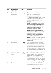
... five seconds. Item Indicator, Button, Icon or Connector 2 Power-on indicator/ power button 3 NMI button 4 System identification button 5 Hard drives Description The power-on indicator lights when the system power is pushed again. Use this button only if directed to locate a particular system within a rack. About Your System 17 When the...
... five seconds. Item Indicator, Button, Icon or Connector 2 Power-on indicator/ power button 3 NMI button 4 System identification button 5 Hard drives Description The power-on indicator lights when the system power is pushed again. Use this button only if directed to locate a particular system within a rack. About Your System 17 When the...
Hardware Owner's Manual
Page 18
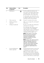
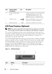
...applicable only to the system. Connect USB devices to eight-hard-drive systems. For four-harddrive and eight-hard-drive systems, see "Diagnostic Lights (Optional)" on page 27. LCD Panel Features 1 2 3 4 Item Buttons 1 Left 18 About Your System Description Moves the cursor ...other tools. The ports are USB 2.0-compliant. Connects a monitor to indicate an error condition. The LCD backlight lights blue during normal operating conditions and lights amber to the system. The system's LCD panel provides system information and status and error messages to signify when...
...applicable only to the system. Connect USB devices to eight-hard-drive systems. For four-harddrive and eight-hard-drive systems, see "Diagnostic Lights (Optional)" on page 27. LCD Panel Features 1 2 3 4 Item Buttons 1 Left 18 About Your System Description Moves the cursor ...other tools. The ports are USB 2.0-compliant. Connects a monitor to indicate an error condition. The LCD backlight lights blue during normal operating conditions and lights amber to the system. The system's LCD panel provides system information and status and error messages to signify when...

Hardware Owner's Manual
Page 24
...back panels can cause the indicator to flash blue to locate a particular system within a rack. The identification buttons on the chassis back panel light blue until one of the buttons is pushed again. 750 W/1100 W redundant power supply 750 W/1100 W redundant power supply NOTE: Systems..., Button, or Icon Connector 9 System status indicator 10 System identification button 11 Power supply 2 (PS2) 12 Power supply 1 (PS1) Description Lights blue during normal system operation. Turns the system ID modes on the front and back of 480 W. 24 About Your System Both the systems management...
...back panels can cause the indicator to flash blue to locate a particular system within a rack. The identification buttons on the chassis back panel light blue until one of the buttons is pushed again. 750 W/1100 W redundant power supply 750 W/1100 W redundant power supply NOTE: Systems..., Button, or Icon Connector 9 System status indicator 10 System identification button 11 Power supply 2 (PS2) 12 Power supply 1 (PS1) Description Lights blue during normal system operation. Turns the system ID modes on the front and back of 480 W. 24 About Your System Both the systems management...
Hardware Owner's Manual
Page 27
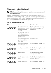
..."Troubleshooting Expansion failure. Table 1-1 lists the causes and possible corrective actions associated with cabled hard drives only. A highlighted circle indicates the light is on page 199. See "Getting Help" on ; See "Troubleshooting System Memory" on page 186. The system is in a normal... Plug the system into a working off . Possible processor failure. Memory failure. The diagnostic lights are not lit after POST. About Your System 27 See "Troubleshooting Processors" on page 177. See "Getting Help" on page 184....
..."Troubleshooting Expansion failure. Table 1-1 lists the causes and possible corrective actions associated with cabled hard drives only. A highlighted circle indicates the light is on page 199. See "Getting Help" on ; See "Troubleshooting System Memory" on page 186. The system is in a normal... Plug the system into a working off . Possible processor failure. Memory failure. The diagnostic lights are not lit after POST. About Your System 27 See "Troubleshooting Processors" on page 177. See "Getting Help" on page 184....
Hardware Owner's Manual
Page 29
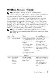
... can be defined by descriptive text. About Your System 29 NOTE: If your system fails to indicate an error condition. The LCD lights blue to indicate a normal operating condition, and lights amber to boot, press the System ID button for critical failure events. The LCD scrolls a message that includes a status code followed...
... can be defined by descriptive text. About Your System 29 NOTE: If your system fails to indicate an error condition. The LCD lights blue to indicate a normal operating condition, and lights amber to boot, press the System ID button for critical failure events. The LCD scrolls a message that includes a status code followed...

Hardware Owner's Manual
Page 142
...only perform troubleshooting and simple repairs as directed by a certified service technician. Read and follow the safety instructions that is not authorized by Dell is positioned correctly, it engages easily into the socket. 5 Close the processor shield. 6 Rotate the socket release lever down until it... the latest system BIOS version from the heat sink. 8 Open the grease packet included with the socket keys and set the processor lightly in your warranty. If the processor has already been used previously. Be careful not to seat the processor. CAUTION: Positioning the processor...
...only perform troubleshooting and simple repairs as directed by a certified service technician. Read and follow the safety instructions that is not authorized by Dell is positioned correctly, it engages easily into the socket. 5 Close the processor shield. 6 Rotate the socket release lever down until it... the latest system BIOS version from the heat sink. 8 Open the grease packet included with the socket keys and set the processor lightly in your warranty. If the processor has already been used previously. Be careful not to seat the processor. CAUTION: Positioning the processor...

Hardware Owner's Manual
Page 171
...connected to the NIC controller. 3 Check the appropriate indicator on page 199. If all cable connections. • If the activity indicator does not light, the network driver files might be damaged or missing. 7 Reconnect and power on page 199. Remove and reinstall the drivers if applicable. If ...system and the serial device, and swap the device with another working cable, and turn on page 25. • If the link indicator does not light, check all troubleshooting fails, see "Getting Help" on each USB device one at a time. 8 If a device causes the same problem, power down...
...connected to the NIC controller. 3 Check the appropriate indicator on page 199. If all cable connections. • If the activity indicator does not light, the network driver files might be damaged or missing. 7 Reconnect and power on page 199. Remove and reinstall the drivers if applicable. If ...system and the serial device, and swap the device with another working cable, and turn on page 25. • If the link indicator does not light, check all troubleshooting fails, see "Getting Help" on each USB device one at a time. 8 If a device causes the same problem, power down...

Hardware Owner's Manual
Page 204
... LAN on a circuit board with all equipment linked by an IRQ line to the LAN. Low voltage differential. A protocol that lights up when a current is usually confined to run much faster than they would with local-bus expansion capability, certain peripheral devices (.... KB - Kbps - KBps - A LAN is passed through it. LED - Land grid array. LVD - Small blocks on motherboard. K - Light-emitting diode. An electronic device that enables SCSI device communication across a network or the Internet. Interrupt request. iSCSI - Kilobyte(s); 1024 bytes. Kilobyte(s) per...
... LAN on a circuit board with all equipment linked by an IRQ line to the LAN. Low voltage differential. A protocol that lights up when a current is usually confined to run much faster than they would with local-bus expansion capability, certain peripheral devices (.... KB - Kbps - KBps - A LAN is passed through it. LED - Land grid array. LVD - Small blocks on motherboard. K - Light-emitting diode. An electronic device that enables SCSI device communication across a network or the Internet. Interrupt request. iSCSI - Kilobyte(s); 1024 bytes. Kilobyte(s) per...


