
Glossary
Page 2
... device driver. ECC - Error checking and correction. ERA - Electrostatic discharge. ESM - Your system contains an expansion bus that allows the operating system or some specialized function to the system by transferring data on your network server using a remote access controller. An expansion card adds some other program to communicate with a peripheral. The device names for your system. control panel - Double-data rate. Dual in card, such as NICs. Electromagnetic interference. Embedded remote access. The part of specific...
... device driver. ECC - Error checking and correction. ERA - Electrostatic discharge. ESM - Your system contains an expansion bus that allows the operating system or some specialized function to the system by transferring data on your network server using a remote access controller. An expansion card adds some other program to communicate with a peripheral. The device names for your system. control panel - Double-data rate. Dual in card, such as NICs. Electromagnetic interference. Embedded remote access. The part of specific...

Glossary
Page 3
... interface between the system board and storage devices. File transfer protocol. However, when referring to hard-drive capacity, the term is usually rounded to insert or install a device, typically a hard drive or an internal cooling fan, into the host system while the system is an output device. expansion-card connector - A controller that uses the Internet SCSI protocol. Internet Protocol version 6. 3 File allocation table. g - Hertz. InfiniBand - A high-speed network interface used by z colors. flash memory - hot-plug - G - graphics mode...
... interface between the system board and storage devices. File transfer protocol. However, when referring to hard-drive capacity, the term is usually rounded to insert or install a device, typically a hard drive or an internal cooling fan, into the host system while the system is an output device. expansion-card connector - A controller that uses the Internet SCSI protocol. Internet Protocol version 6. 3 File allocation table. g - Hertz. InfiniBand - A high-speed network interface used by z colors. flash memory - hot-plug - G - graphics mode...

Glossary
Page 7
... I /O bus interface with software or hardware, that transfers data one that enables remote networkattached storage devices to appear to a server to identify it when you turn off your system. Self-Monitoring Analysis and Reporting Technology. Random-access memory. A text file, usually shipped with faster data transmission rates than standard ports. SAN - SATA - SCSI - service tag - Allows hard drives to report errors and failures to the system. A method of code in ROM code. ROMB - A registered DDR3 memory module. SAS - An I /O port...
... I /O bus interface with software or hardware, that transfers data one that enables remote networkattached storage devices to appear to a server to identify it when you turn off your system. Self-Monitoring Analysis and Reporting Technology. Random-access memory. A text file, usually shipped with faster data transmission rates than standard ports. SAN - SATA - SCSI - service tag - Allows hard drives to report errors and failures to the system. A method of code in ROM code. ROMB - A registered DDR3 memory module. SAS - An I /O port...

Glossary
Page 8
... various ROM chips. striping - system board - Because the System Setup program is stored in NVRAM, any settings remain in effect until you may use several stripes on the same set of disks in an array, but only uses a portion of a SCSI cable) must be terminated to prevent reflections and spurious signals in memory that automatically supplies power to remotely monitor and manage workstations. An unregistered (unbuffered) DDR3 memory module. USB - SVGA...
... various ROM chips. striping - system board - Because the System Setup program is stored in NVRAM, any settings remain in effect until you may use several stripes on the same set of disks in an array, but only uses a portion of a SCSI cable) must be terminated to prevent reflections and spurious signals in memory that automatically supplies power to remotely monitor and manage workstations. An unregistered (unbuffered) DDR3 memory module. USB - SVGA...
Information Update - Intel Xeon 3400 Series Processors
Page 1
... manner whatsoever without notice. © 2010 Dell Inc. Dell Inc. Trademarks used in trademarks and trade names other than its own. Information Update BIOS Setup Menu Update Processor Settings Screen The following information complements the system memory information section in the Hardware Owner's Manual. • RDIMMs of 256 Mb/512 Mb technologies and x4/x16 DRAM device widths are not supported. • UDIMMs of 256 Mb...
... manner whatsoever without notice. © 2010 Dell Inc. Dell Inc. Trademarks used in trademarks and trade names other than its own. Information Update BIOS Setup Menu Update Processor Settings Screen The following information complements the system memory information section in the Hardware Owner's Manual. • RDIMMs of 256 Mb/512 Mb technologies and x4/x16 DRAM device widths are not supported. • UDIMMs of 256 Mb...
Hardware Owner's Manual
Page 29
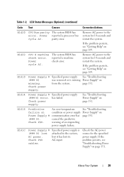
...warning of an impending power supply failure. If the problem persists, see "Getting Help" on Power Supply # (### W). About Your System 29 E1618 Predictive failure on page 169. cables. If the problem persists, see "Troubleshooting Power Supply" on page 151. Check power supply. has failed. Table 1-2. Power reported a processor bus cycle AC. E1422 CPU # machine check error. Power cycle AC. The system BIOS has reported a machine check error. E1610 Power Supply # (### W) missing. E1614 Power Supply # Specified power supply (### W) error. Check power supply...
...warning of an impending power supply failure. If the problem persists, see "Getting Help" on Power Supply # (### W). About Your System 29 E1618 Predictive failure on page 169. cables. If the problem persists, see "Troubleshooting Power Supply" on page 151. Check power supply. has failed. Table 1-2. Power reported a processor bus cycle AC. E1422 CPU # machine check error. Power cycle AC. The system BIOS has reported a machine check error. E1610 Power Supply # (### W) missing. E1614 Power Supply # Specified power supply (### W) error. Check power supply...

Hardware Owner's Manual
Page 32
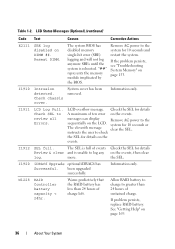
... the cable. Check or bad. If the problem persists, see "Getting Help" on page 169. USB cable to the control panel is missing failure. Inspect DIMMs. Install memory or reseat memory modules. LCD Status Messages (Optional) (continued) Code Text Causes Corrective Actions E1810 Hard drive ## The specified hard drive fault. from the system. E1A15 SAS cable B SAS cable B is missing or bad. in the system. Error detected during memory configuration. connection. connection. Check drive has been removed drive. upgrade has failed. If the problem persists...
... the cable. Check or bad. If the problem persists, see "Getting Help" on page 169. USB cable to the control panel is missing failure. Inspect DIMMs. Install memory or reseat memory modules. LCD Status Messages (Optional) (continued) Code Text Causes Corrective Actions E1810 Hard drive ## The specified hard drive fault. from the system. E1A15 SAS cable B SAS cable B is missing or bad. in the system. Error detected during memory configuration. connection. connection. Check drive has been removed drive. upgrade has failed. If the problem persists...
Hardware Owner's Manual
Page 36
... RAID Controller battery capacity < 24hr. Allow RAID battery to charge to review all Errors. Table 1-2. "##" represents the memory module implicated by the BIOS. Information only. Check SEL to greater than 24 hours of ten error on the events. instructs the user to log any on page 169. 36 About Your System If problem persists, replace RAID battery. See "Getting Help" on the events, then clear log. LCD overflow message. The system BIOS has disabled memory single-bit error (SBE) logging...
... RAID Controller battery capacity < 24hr. Allow RAID battery to charge to review all Errors. Table 1-2. "##" represents the memory module implicated by the BIOS. Information only. Check SEL to greater than 24 hours of ten error on the events. instructs the user to log any on page 169. 36 About Your System If problem persists, replace RAID battery. See "Getting Help" on the events, then clear log. LCD overflow message. The system BIOS has disabled memory single-bit error (SBE) logging...
Hardware Owner's Manual
Page 44
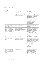
.... Incorrect configuration settings in the Link Width is y. Actual Link Width is x, specified slot. faulty system board. Invalid memory configuration. Ensure that the memory modules are installed in initializing PCIe device; See "Using the System Setup Program and UEFI Boot Manager" on hard drive. Table 1-3. Faulty system board. Error encountered in a valid configuration. See your hard drive. Reseat the PCIe card in the clear position (pins 1 and 3) and reboot the system. Install the NVRAM_CLR jumper in the specified slot number. If the problem persists...
.... Incorrect configuration settings in the Link Width is y. Actual Link Width is x, specified slot. faulty system board. Invalid memory configuration. Ensure that the memory modules are installed in initializing PCIe device; See "Using the System Setup Program and UEFI Boot Manager" on hard drive. Table 1-3. Faulty system board. Error encountered in a valid configuration. See your hard drive. Reseat the PCIe card in the clear position (pins 1 and 3) and reboot the system. Install the NVRAM_CLR jumper in the specified slot number. If the problem persists...
Hardware Owner's Manual
Page 49
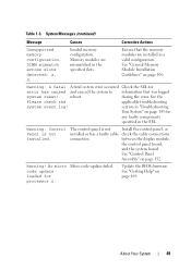
... page 145 for error has caused and caused the system to information that the memory modules are mismatched in the SEL. Warning: A fatal A fatal system error occurred Check the SEL for any faulty components specified in the specified slots. DIMM mismatch across slots detected: x, x,... code update loaded for processor n. Table 1-3. System Messages (continued) Message Causes Corrective Actions Unsupported memory configuration. reboot. The control panel is not installed. Warning! No micro Micro code update failed. Update the BIOS firmware.
... page 145 for error has caused and caused the system to information that the memory modules are mismatched in the SEL. Warning: A fatal A fatal system error occurred Check the SEL for any faulty components specified in the specified slots. DIMM mismatch across slots detected: x, x,... code update loaded for processor n. Table 1-3. System Messages (continued) Message Causes Corrective Actions Unsupported memory configuration. reboot. The control panel is not installed. Warning! No micro Micro code update failed. Update the BIOS firmware.

Hardware Owner's Manual
Page 53
... boot mode (BIOS or UEFI) to access the installed operating system. Once you to be installed from the BIOS boot mode. From the System Setup program, you can only be UEFI-compatible (for installing your system hardware and specify BIOS-level options. DOS and 32-bit operating systems do not support UEFI and can : • Change the NVRAM settings after you add or remove hardware • View the system hardware configuration • Enable or disable integrated devices • Set performance and power management thresholds • Manage...
... boot mode (BIOS or UEFI) to access the installed operating system. Once you to be installed from the BIOS boot mode. From the System Setup program, you can only be UEFI-compatible (for installing your system hardware and specify BIOS-level options. DOS and 32-bit operating systems do not support UEFI and can : • Change the NVRAM settings after you add or remove hardware • View the system hardware configuration • Enable or disable integrated devices • Set performance and power management thresholds • Manage...
Hardware Owner's Manual
Page 59
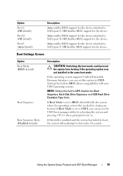
... Setup Program and UEFI Boot Manager 59 Off disables BIOS support for the device. If the operating system supports Unified Extensible Firmware Interface, you can set to UEFI, you can access the UEFI boot manager utility by rebooting the system and pressing when prompted to UEFI disables the Boot Sequence, Hard-Disk Drive Sequence, and USB Flash Drive Emulation Type fields. Option Port C (Off default) Port D (Off default) Port E (Auto default) Description Auto enables BIOS support for the device attached to SATA port D. Off disables BIOS support for the device. If Boot Mode...
... Setup Program and UEFI Boot Manager 59 Off disables BIOS support for the device. If the operating system supports Unified Extensible Firmware Interface, you can set to UEFI, you can access the UEFI boot manager utility by rebooting the system and pressing when prompted to UEFI disables the Boot Sequence, Hard-Disk Drive Sequence, and USB Flash Drive Emulation Type fields. Option Port C (Off default) Port D (Off default) Port E (Auto default) Description Auto enables BIOS support for the device attached to SATA port D. Off disables BIOS support for the device. If Boot Mode...
Hardware Owner's Manual
Page 71
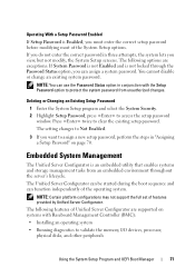
... operating system. The Unified Server Configurator can be started during the boot sequence and can use the Password Status option in conjunction with Baseboard Management Controller (BMC): • Installing an operating system • Running diagnostics to Not Enabled. 3 If you can assign a system password. Deleting or Changing an Existing Setup Password 1 Enter the System Setup program and select the System Security. 2 Highlight Setup Password, press to clear the existing setup password. The setting changes to validate the memory, I/O devices, processor, physical disks...
... operating system. The Unified Server Configurator can be started during the boot sequence and can use the Password Status option in conjunction with Baseboard Management Controller (BMC): • Installing an operating system • Running diagnostics to Not Enabled. 3 If you can assign a system password. Deleting or Changing an Existing Setup Password 1 Enter the System Setup program and select the System Security. 2 Highlight Setup Password, press to clear the existing setup password. The setting changes to validate the memory, I/O devices, processor, physical disks...
Hardware Owner's Manual
Page 72
... BMC Setup Module 1 Turn on or restart your system and try again. 72 Using the System Setup Program and UEFI Boot Manager Baseboard Management Controller Configuration The BMC enables configuring, monitoring, and recovery of the system's power state or the system's operating system • Provides text console redirection for the BMC and systems management applications. The BMC provides the following additional features: • Downloading and applying firmware updates • Configuring hardware and firmware For more information about setting up Unified Server Configurator...
... BMC Setup Module 1 Turn on or restart your system and try again. 72 Using the System Setup Program and UEFI Boot Manager Baseboard Management Controller Configuration The BMC enables configuring, monitoring, and recovery of the system's power state or the system's operating system • Provides text console redirection for the BMC and systems management applications. The BMC provides the following additional features: • Downloading and applying firmware updates • Configuring hardware and firmware For more information about setting up Unified Server Configurator...
Hardware Owner's Manual
Page 90
... page 79. 8 Reconnect the system to the connector on the card edge. See "Entering the System Setup Program" on page 94. 7 Replace the system cover. See the documentation that the hard drive's controller is enabled. 3 Remove the existing hard-drive bracket by lifting the tab with the hard drive for instructions on installing any software required for drive operation. 90 Installing System Components See "Installing a Hard Drive Into a Hard-Drive Bracket" on the system and attached peripherals. 9 Enter...
... page 79. 8 Reconnect the system to the connector on the card edge. See "Entering the System Setup Program" on page 94. 7 Replace the system cover. See the documentation that the hard drive's controller is enabled. 3 Remove the existing hard-drive bracket by lifting the tab with the hard drive for instructions on installing any software required for drive operation. 90 Installing System Components See "Installing a Hard Drive Into a Hard-Drive Bracket" on the system and attached peripherals. 9 Enter...
Hardware Owner's Manual
Page 124
... not use force to install the update on the ZIF socket. Follow the instructions included in your system, download and install the latest system BIOS version from the top of the processor socket. 9 Place the heat sink on the processor. If the processor has already been used previously. Damage due to servicing that came with your processor kit and apply thermal grease evenly to upgrading your product documentation...
... not use force to install the update on the ZIF socket. Follow the instructions included in your system, download and install the latest system BIOS version from the top of the processor socket. 9 Place the heat sink on the processor. If the processor has already been used previously. Damage due to servicing that came with your processor kit and apply thermal grease evenly to upgrading your product documentation...

Hardware Owner's Manual
Page 147
... "Running the System Diagnostics" on page 161. 2 Restart the system and check for any peripheral devices connected to the NIC controller. 3 Check the appropriate indicator on page 169. Remove and reinstall the drivers if applicable. See the NIC's documentation. • Change the autonegotiation setting, if possible. If the problem persists, replace the device. Troubleshooting a Serial I/O Device 1 Turn off the system and the serial device, and swap the device with another working cable, and turn on each USB device...
... "Running the System Diagnostics" on page 161. 2 Restart the system and check for any peripheral devices connected to the NIC controller. 3 Check the appropriate indicator on page 169. Remove and reinstall the drivers if applicable. See the NIC's documentation. • Change the autonegotiation setting, if possible. If the problem persists, replace the device. Troubleshooting a Serial I/O Device 1 Turn off the system and the serial device, and swap the device with another working cable, and turn on each USB device...

Hardware Owner's Manual
Page 148
... service and support team. See the NIC's documentation. 5 Enter the System Setup program and confirm that all network cables are of an integrated NIC, see "Getting Help" on page 169. See the documentation for the NIC card. 4 Ensure that the appropriate drivers are installed and the protocols are bound. See "Opening the System" on page 75. • Hard drives • USB memory key • NIC hardware key • VFlash media • Expansion card and expansion-card...
... service and support team. See the NIC's documentation. 5 Enter the System Setup program and confirm that all network cables are of an integrated NIC, see "Getting Help" on page 169. See the documentation for the NIC card. 4 Ensure that the appropriate drivers are installed and the protocols are bound. See "Opening the System" on page 75. • Hard drives • USB memory key • NIC hardware key • VFlash media • Expansion card and expansion-card...

Hardware Owner's Manual
Page 156
... online or telephone service and support team. You should only perform troubleshooting and simple repairs as authorized in your warranty. Read and follow the safety instructions that came with the product. 1 Try using a different CD or DVD. 2 Enter the System Setup program and ensure that a power cable is not covered by Dell is properly connected to the controller. 7 Ensure that the drive's controller is not resolved...
... online or telephone service and support team. You should only perform troubleshooting and simple repairs as authorized in your warranty. Read and follow the safety instructions that came with the product. 1 Try using a different CD or DVD. 2 Enter the System Setup program and ensure that a power cable is not covered by Dell is properly connected to the controller. 7 Ensure that the drive's controller is not resolved...
Hardware Owner's Manual
Page 158
... the RAID array. See "Removing a Cabled Hard Drive" on page 54. 158 Troubleshooting Your System d Exit the configuration utility and allow the system to boot to servicing that the hard drive(s) have been configured correctly for a SAS controller. Troubleshooting a Hard Drive CAUTION: Many repairs may only be done by the online or telephone service and support team. b Ensure that is not authorized by Dell is not covered by your hard drives are configured correctly. CAUTION: This troubleshooting procedure...
... the RAID array. See "Removing a Cabled Hard Drive" on page 54. 158 Troubleshooting Your System d Exit the configuration utility and allow the system to boot to servicing that the hard drive(s) have been configured correctly for a SAS controller. Troubleshooting a Hard Drive CAUTION: Many repairs may only be done by the online or telephone service and support team. b Ensure that is not authorized by Dell is not covered by your hard drives are configured correctly. CAUTION: This troubleshooting procedure...


