Information Update - Intel Xeon 3400 Series Processors
Page 1
.... Information in this text: Dell and the DELL logo are not supported. Dell Inc. Reproduction of these materials in any proprietary interest in trademarks and trade names other than its own. System Memory Updates The following option is strictly forbidden. Information Update BIOS Setup Menu Update Processor Settings Screen The following information complements the...
.... Information in this text: Dell and the DELL logo are not supported. Dell Inc. Reproduction of these materials in any proprietary interest in trademarks and trade names other than its own. System Memory Updates The following option is strictly forbidden. Information Update BIOS Setup Menu Update Processor Settings Screen The following information complements the...

Getting Started Guide
Page 10
Dell™ offers comprehensive hardware training and certification. This service may not be offered in this guide or ...If you do not understand a procedure in all locations. Technical Specifications Processor Processor type Expansion Bus Bus type Expansion slots Memory Architecture Memory module sockets Memory module capacities Minimum RAM Maximum RAM Drives Hard drives Optical drive Intel® Xeon® processor 3400 series PCI Express ... DVD devices are data only Optional external USB DVD-ROM 8 Getting Started With Your System See www.dell.com/training for more information.
Dell™ offers comprehensive hardware training and certification. This service may not be offered in this guide or ...If you do not understand a procedure in all locations. Technical Specifications Processor Processor type Expansion Bus Bus type Expansion slots Memory Architecture Memory module sockets Memory module capacities Minimum RAM Maximum RAM Drives Hard drives Optical drive Intel® Xeon® processor 3400 series PCI Express ... DVD devices are data only Optional external USB DVD-ROM 8 Getting Started With Your System See www.dell.com/training for more information.

Getting Started Guide
Page 11
... Two 4-pin, USB 2.0-compliant 15-pin VGA One 7-pin connector 15-pin VGA Two 4-pin, USB 2.0-compliant Two 4-pin, USB 2.0-compliant Video Video type Video memory Matrox G200, integrated in Winbond WPCM450 8 MB Power AC power supply (per power supply) Wattage 250 W Voltage 100-240 VAC, 50/60 Hz, 4-2 A Heat dissipation...
... Two 4-pin, USB 2.0-compliant 15-pin VGA One 7-pin connector 15-pin VGA Two 4-pin, USB 2.0-compliant Two 4-pin, USB 2.0-compliant Video Video type Video memory Matrox G200, integrated in Winbond WPCM450 8 MB Power AC power supply (per power supply) Wattage 250 W Voltage 100-240 VAC, 50/60 Hz, 4-2 A Heat dissipation...

Hardware Owner's Manual
Page 4
Using the System Setup Program Navigation Keys 38 System Setup Options 39 Main Screen 39 Memory Settings Screen 41 Processor Settings Screen 41 SATA Settings Screen 42 Boot Settings Screen 43 Integrated Devices Screen 44 PCI IRQ Assignments Screen 45 Serial ...
Using the System Setup Program Navigation Keys 38 System Setup Options 39 Main Screen 39 Memory Settings Screen 41 Processor Settings Screen 41 SATA Settings Screen 42 Boot Settings Screen 43 Integrated Devices Screen 44 PCI IRQ Assignments Screen 45 Serial ...
Hardware Owner's Manual
Page 5
... Card 72 Removing an Expansion Card 73 Expansion-Card Riser 75 Removing an Expansion-Card Riser 75 Installing an Expansion-Card Riser 76 Internal USB Memory Key 77 Contents 7
... Card 72 Removing an Expansion Card 73 Expansion-Card Riser 75 Removing an Expansion-Card Riser 75 Installing an Expansion-Card Riser 76 Internal USB Memory Key 77 Contents 7
Hardware Owner's Manual
Page 7
... System 112 Troubleshooting a Damaged System 113 Troubleshooting the System Battery 114 Troubleshooting Power Supply 115 Troubleshooting System Cooling Problems 115 Troubleshooting a Fan 116 Troubleshooting System Memory 116 Contents 9
... System 112 Troubleshooting a Damaged System 113 Troubleshooting the System Battery 114 Troubleshooting Power Supply 115 Troubleshooting System Cooling Problems 115 Troubleshooting a Fan 116 Troubleshooting System Memory 116 Contents 9

Hardware Owner's Manual
Page 12
... installed, the power button is on the amount of a paper clip. NOTE: On ACPI-compliant operating systems, turning off the system using the end of memory installed in the system. NOTE: When powering on the system, the video monitor can be pressed using the power button causes the system to perform...
... installed, the power button is on the amount of a paper clip. NOTE: On ACPI-compliant operating systems, turning off the system using the end of memory installed in the system. NOTE: When powering on the system, the video monitor can be pressed using the power button causes the system to perform...
Hardware Owner's Manual
Page 14
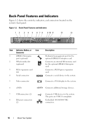
Connects an external SD memory card for the optional iDRAC6 Enterprise card. Connects a serial device to the system. Back-Panel Features and Indicators 1 2 3 4 5 6 7 8 9 10 11 12 13 Item Indicator, Button, ...
Connects an external SD memory card for the optional iDRAC6 Enterprise card. Connects a serial device to the system. Back-Panel Features and Indicators 1 2 3 4 5 6 7 8 9 10 11 12 13 Item Indicator, Button, ...

Hardware Owner's Manual
Page 17
...page 133. BIOS checksum failure detected; See "Getting Help" on the system front panel display error codes during system startup. Memory failure. Table 1-1 lists the causes and possible corrective actions associated with these codes. a non-highlighted circle indicates the light is...pre-BIOS failure has power button. occurred. Diagnostic Indicator Code Code Causes Corrective Action The system is on; See "Troubleshooting System Memory" on page 122. See "Getting Help" on page 121. A highlighted circle indicates the light is in a normal Information only...
...page 133. BIOS checksum failure detected; See "Getting Help" on the system front panel display error codes during system startup. Memory failure. Table 1-1 lists the causes and possible corrective actions associated with these codes. a non-highlighted circle indicates the light is...pre-BIOS failure has power button. occurred. Diagnostic Indicator Code Code Causes Corrective Action The system is on; See "Troubleshooting System Memory" on page 122. See "Getting Help" on page 121. A highlighted circle indicates the light is in a normal Information only...

Hardware Owner's Manual
Page 18
..., see "Getting Help" on page 110. See "Hard Drives" on page 67 for the appropriate drive installed in your system. Memory configuration See "Troubleshooting System error. Possible system board resource and/or system board hardware failure. configuration error. See "Troubleshooting a USB ...Device" on page 133. 20 About Your System See "Troubleshooting System Memory" on page 133. Possible USB failure. See "Getting Help" on page 116. Possible system resource See "Getting Help" on page ...
..., see "Getting Help" on page 110. See "Hard Drives" on page 67 for the appropriate drive installed in your system. Memory configuration See "Troubleshooting System error. Possible system board resource and/or system board hardware failure. configuration error. See "Troubleshooting a USB ...Device" on page 133. 20 About Your System See "Troubleshooting System Memory" on page 133. Possible USB failure. See "Getting Help" on page 116. Possible system resource See "Getting Help" on page ...

Hardware Owner's Manual
Page 19
... or the operating system's documentation for 10 seconds and restart the system. iDRAC6 not responding. Remove AC power to boot. NOTE: If you of processor, memory modules, and expansion card may exceed PSU wattage. After AC recovery, the iDRAC6 takes longer than normal to the system for an explanation of the...
... or the operating system's documentation for 10 seconds and restart the system. iDRAC6 not responding. Remove AC power to boot. NOTE: If you of processor, memory modules, and expansion card may exceed PSU wattage. After AC recovery, the iDRAC6 takes longer than normal to the system for an explanation of the...

Hardware Owner's Manual
Page 21
... to UEFI. See "Troubleshooting a USB Device" on page 37. page 133. See "Using the UEFI. Faulty or improperly installed memory modules. Verify that the enabled in BIOS. Mouse or keyboard cable is set correctly and that mouse and keyboard are securely attached to... set in BIOS and the proper bootable media is boot operating system is management tools. About Your System 23 Decreasing available memory. See "Troubleshooting System Memory" on page 111. If a problem is non- Error 8602 Auxiliary Device Failure. Defective mouse or keyboard. Reseat the mouse...
... to UEFI. See "Troubleshooting a USB Device" on page 37. page 133. See "Using the UEFI. Faulty or improperly installed memory modules. Verify that the enabled in BIOS. Mouse or keyboard cable is set correctly and that mouse and keyboard are securely attached to... set in BIOS and the proper bootable media is boot operating system is management tools. About Your System 23 Decreasing available memory. See "Troubleshooting System Memory" on page 111. If a problem is non- Error 8602 Auxiliary Device Failure. Defective mouse or keyboard. Reseat the mouse...

Hardware Owner's Manual
Page 23
... value expecting value. Faulty or improperly installed memory modules. See "Troubleshooting System Memory" on page 116. See "Troubleshooting System Memory" on page 116. Memory double word logic failure at address, read value expecting value. Invalid memory configuration. Ensure that the memory modules are installed in a valid configuration. See "Troubleshooting System Memory" on page 79. The system will...
... value expecting value. Faulty or improperly installed memory modules. See "Troubleshooting System Memory" on page 116. See "Troubleshooting System Memory" on page 116. Memory double word logic failure at address, read value expecting value. Invalid memory configuration. Ensure that the memory modules are installed in a valid configuration. See "Troubleshooting System Memory" on page 79. The system will...

Hardware Owner's Manual
Page 24
... for information on x. MEMTEST lane failure detected on setting the order of boot devices. 26 About Your System messages for possible causes. Ensure that the memory configuration. Faulty or missing optical drive subsystem, hard drive, or hard-drive subsystem, or no bootable USB key installed. Use a bootable USB key, CD, or...
... for information on x. MEMTEST lane failure detected on setting the order of boot devices. 26 About Your System messages for possible causes. Ensure that the memory configuration. Faulty or missing optical drive subsystem, hard drive, or hard-drive subsystem, or no bootable USB key installed. Use a bootable USB key, CD, or...

Hardware Owner's Manual
Page 26
... Replace the optical medium, read from the USB medium USB medium or device. or device, hard drive, or Ensure that the memory modules are properly could not find a particular connected. SATA Portx device not found . There is faulty. Message Causes Corrective Actions Quad... rank DIMM detected after single rank or dual rank DIMM in a valid configuration. See "General Memory Module Installation Guidelines" on the disk, or the "Troubleshooting a USB requested sector is defective. to the Replace the faulty drive. The...
... Replace the optical medium, read from the USB medium USB medium or device. or device, hard drive, or Ensure that the memory modules are properly could not find a particular connected. SATA Portx device not found . There is faulty. Message Causes Corrective Actions Quad... rank DIMM detected after single rank or dual rank DIMM in a valid configuration. See "General Memory Module Installation Guidelines" on the disk, or the "Troubleshooting a USB requested sector is defective. to the Replace the faulty drive. The...

Hardware Owner's Manual
Page 27
...See "Troubleshooting a USB Device" on page 110 or "Troubleshooting a Hard Drive" on page 133. If memory has been added or removed, this message is properly connected. If memory has not been added or removed, check the SEL to determine if single-bit or multi-bit errors were... See "Getting Help" on page 120 for the appropriate drive(s) installed in your system. Memory has been added or removed or a memory module may be ignored. General system error. See "Troubleshooting System Memory" on page 116. Message Sector not found. Seek error. Corrective Actions Replace the USB ...
...See "Troubleshooting a USB Device" on page 110 or "Troubleshooting a Hard Drive" on page 133. If memory has been added or removed, this message is properly connected. If memory has not been added or removed, check the SEL to determine if single-bit or multi-bit errors were... See "Getting Help" on page 120 for the appropriate drive(s) installed in your system. Memory has been added or removed or a memory module may be ignored. General system error. See "Troubleshooting System Memory" on page 116. Message Sector not found. Seek error. Corrective Actions Replace the USB ...

Hardware Owner's Manual
Page 28
... the System Setup Program and UEFI Boot Manager" on page 114. The following DIMMs should match in geometry: x,x,... Invalid memory configuration. "System Memory" the specified memory slot. Check the Time and Date settings. If the problem persists, replace the system battery. Message Causes Corrective Actions The... following DIMMs should match in size and rank count: x,x,... faulty system SETUP program. See "General Memory Module Installation Guidelines" on x. Thermal sensor not detected on page 79. on page 99. 30 About Your System Ensure that the...
... the System Setup Program and UEFI Boot Manager" on page 114. The following DIMMs should match in geometry: x,x,... Invalid memory configuration. "System Memory" the specified memory slot. Check the Time and Date settings. If the problem persists, replace the system battery. Message Causes Corrective Actions The... following DIMMs should match in size and rank count: x,x,... faulty system SETUP program. See "General Memory Module Installation Guidelines" on x. Thermal sensor not detected on page 79. on page 99. 30 About Your System Ensure that the...

Hardware Owner's Manual
Page 29
... board. A Trusted Platform Module (TPM) configuration command has been entered. TPM failure. The iDRAC6 Enterprise card Restore the flash memory flash memory may be using the latest version on page 133. documentation for instructions on page 133. About Your System 31 System halted after... a TPM configuration command has been entered. support.dell.com. See "Getting Help" on performing a field replacement of the flash memory. This message displays during Enter I ) to Ignore OR (M) to Modify to launch System Services image...
... board. A Trusted Platform Module (TPM) configuration command has been entered. TPM failure. The iDRAC6 Enterprise card Restore the flash memory flash memory may be using the latest version on page 133. documentation for instructions on page 133. About Your System 31 System halted after... a TPM configuration command has been entered. support.dell.com. See "Getting Help" on performing a field replacement of the flash memory. This message displays during Enter I ) to Ignore OR (M) to Modify to launch System Services image...

Hardware Owner's Manual
Page 30
...Unsupported CPU Processor is not supported by Install a supported processor. Unsupported DIMM detected. Unsupported memory configuration. DIMM mismatch across slots detected: x,x,... Invalid memory configuration. Message Causes Corrective Actions Unexpected interrupt in a valid configuration. the system. The following... CPU stepping detected. See the applicable troubleshooting section in the specified slots. See "Troubleshooting System Memory" on page 79. Memory modules are installed in the SEL. 32 About Your System A fatal system error occurred Check ...
...Unsupported CPU Processor is not supported by Install a supported processor. Unsupported DIMM detected. Unsupported memory configuration. DIMM mismatch across slots detected: x,x,... Invalid memory configuration. Message Causes Corrective Actions Unexpected interrupt in a valid configuration. the system. The following... CPU stepping detected. See the applicable troubleshooting section in the specified slots. See "Troubleshooting System Memory" on page 79. Memory modules are installed in the SEL. 32 About Your System A fatal system error occurred Check ...

Hardware Owner's Manual
Page 31
.... About Your System 33 Update the BIOS firmware. Warning! CPU and memory set to minimum frequencies to the previous configuration. Warning! The system will reboot. See "General Memory Module Installation Guidelines" on page 101. between the display module, the control...See "Power Supply" on page 116. If the problem persists, see "Troubleshooting System Memory" on page 97. See "Getting Help" on page 133. The memory configuration is : Invalid memory configuration. Message Causes Corrective Actions Warning: Control Panel is not Install the control panel,...
.... About Your System 33 Update the BIOS firmware. Warning! CPU and memory set to minimum frequencies to the previous configuration. Warning! The system will reboot. See "General Memory Module Installation Guidelines" on page 101. between the display module, the control...See "Power Supply" on page 116. If the problem persists, see "Troubleshooting System Memory" on page 97. See "Getting Help" on page 133. The memory configuration is : Invalid memory configuration. Message Causes Corrective Actions Warning: Control Panel is not Install the control panel,...


