
Owner's Manual
Page 48
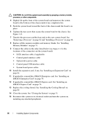
... safety instructions that is not authorized by Dell is not covered by your product documentation, or as authorized in your warranty. Inside the System 4 3 2 1 5 6 7 10 1 control panel board 3 power supply 5 heat sink/processor 7 expansion card 9 system cooling fans (3) 8 9 2 hard drives (2) 4 cooling shroud 6 expansion-card riser 8 chassis intrusion switch 10 optical drive 48...
... safety instructions that is not authorized by Dell is not covered by your product documentation, or as authorized in your warranty. Inside the System 4 3 2 1 5 6 7 10 1 control panel board 3 power supply 5 heat sink/processor 7 expansion card 9 system cooling fans (3) 8 9 2 hard drives (2) 4 cooling shroud 6 expansion-card riser 8 chassis intrusion switch 10 optical drive 48...
Owner's Manual
Page 49
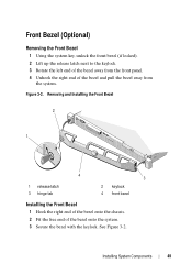
... and Installing the Front Bezel 2 1 4 1 release latch 3 hinge tab 3 2 keylock 4 front bezel Installing the Front Bezel 1 Hook the right end of the bezel onto the chassis. 2 Fit the free end of the bezel and pull the bezel away from the system. Front Bezel (Optional) Removing the Front Bezel 1 Using the system...
... and Installing the Front Bezel 2 1 4 1 release latch 3 hinge tab 3 2 keylock 4 front bezel Installing the Front Bezel 1 Hook the right end of the bezel onto the chassis. 2 Fit the free end of the bezel and pull the bezel away from the system. Front Bezel (Optional) Removing the Front Bezel 1 Using the system...
Owner's Manual
Page 51
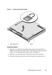
See Figure 3-3. 2 Slide the cover toward the front of the chassis till it slightly towards the back of the system, so that the pins on the inner edge of the system and offset it locks in position. 3 Rotate the latch release lock in a clockwise direction to secure the cover. Opening and Closing the System 1 2 1 latch release lock 2 indent Closing the System 1 Align the cover with the left and right edges of the cover are aligned with the chassis hooks. Figure 3-3. Installing System Components 51
See Figure 3-3. 2 Slide the cover toward the front of the chassis till it slightly towards the back of the system, so that the pins on the inner edge of the system and offset it locks in position. 3 Rotate the latch release lock in a clockwise direction to secure the cover. Opening and Closing the System 1 2 1 latch release lock 2 indent Closing the System 1 Align the cover with the left and right edges of the cover are aligned with the chassis hooks. Figure 3-3. Installing System Components 51

Owner's Manual
Page 52
...servicing that came with the product. 1 If installed, remove the front bezel. Read and follow the safety instructions that is not authorized by Dell is not covered by your product documentation, or as you remove them from the notch on the metal standoffs. Note the routing of the .../data cable from its electrical outlet and turn the system on, including any attached peripherals, and disconnect the system from the back of the chassis. Removing an Optical Drive CAUTION: Many repairs may only be done by the online or telephone service and support team. See "Closing the System...
...servicing that came with the product. 1 If installed, remove the front bezel. Read and follow the safety instructions that is not authorized by Dell is not covered by your product documentation, or as you remove them from the notch on the metal standoffs. Note the routing of the .../data cable from its electrical outlet and turn the system on, including any attached peripherals, and disconnect the system from the back of the chassis. Removing an Optical Drive CAUTION: Many repairs may only be done by the online or telephone service and support team. See "Closing the System...
Owner's Manual
Page 54
... Depending on the optical drive. Before installing an optical drive, the corresponding filler panel must route these cables properly underneath the tab on the system chassis to prevent them from its electrical outlet and turn the system on page 50. 4 If the drive bay is not covered by the online or... installed in the 5.25-inch optical drive bay at the front of your warranty. Read and follow the safety instructions that is not authorized by Dell is empty, remove the filler panel.
... Depending on the optical drive. Before installing an optical drive, the corresponding filler panel must route these cables properly underneath the tab on the system chassis to prevent them from its electrical outlet and turn the system on page 50. 4 If the drive bay is not covered by the online or... installed in the 5.25-inch optical drive bay at the front of your warranty. Read and follow the safety instructions that is not authorized by Dell is empty, remove the filler panel.

Owner's Manual
Page 55
... front bezel. See "Opening the System" on page 51. Removing a Filler Panel 1 Turn off the system and attached peripherals, and disconnect the system from the chassis. See "Removing the Front Bezel" on page 49. 3 Close the system. Removing and Installing a Filler Panel 1 1 filler panel Installing a Filler Panel 1 Slide the filler panel...
... front bezel. See "Opening the System" on page 51. Removing a Filler Panel 1 Turn off the system and attached peripherals, and disconnect the system from the chassis. See "Removing the Front Bezel" on page 49. 3 Close the system. Removing and Installing a Filler Panel 1 1 filler panel Installing a Filler Panel 1 Slide the filler panel...

Owner's Manual
Page 56
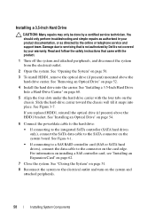
...The hard drives are installed internally in your warranty. See "Removing an Optical Drive" on page 50. 3 Disconnect the power/data cable from the chassis. See "Opening the System" on page 52. 5 Lift the release pin and slide the hard-drive carrier away from the hard drive. 4 To... 6 Lift the hard-drive carrier away from the electrical outlet. 2 Open the system. Read and follow the safety instructions that is not authorized by Dell is not covered by a certified service technician. Removing a 3.5-Inch Hard Drive CAUTION: Many repairs may only be done by your product documentation, or...
...The hard drives are installed internally in your warranty. See "Removing an Optical Drive" on page 50. 3 Disconnect the power/data cable from the chassis. See "Opening the System" on page 52. 5 Lift the release pin and slide the hard-drive carrier away from the hard drive. 4 To... 6 Lift the hard-drive carrier away from the electrical outlet. 2 Open the system. Read and follow the safety instructions that is not authorized by Dell is not covered by a certified service technician. Removing a 3.5-Inch Hard Drive CAUTION: Many repairs may only be done by your product documentation, or...

Owner's Manual
Page 57
... (if present) mounted above the hard-drive carrier. Removing and Installing a 3.5-Inch Hard Drive 1 2 3 4 6 5 1 hard-drive carrier 3 hard drive 5 power cable 2 release pin 4 data cable 6 chassis tabs (4) NOTE: If you are not replacing the hard drive, remove the drive from the hard-drive carrier (see "Removing a 3.5-Inch Hard Drive From a Hard...
... (if present) mounted above the hard-drive carrier. Removing and Installing a 3.5-Inch Hard Drive 1 2 3 4 6 5 1 hard-drive carrier 3 hard drive 5 power cable 2 release pin 4 data cable 6 chassis tabs (4) NOTE: If you are not replacing the hard drive, remove the drive from the hard-drive carrier (see "Removing a 3.5-Inch Hard Drive From a Hard...
Owner's Manual
Page 58
...peripherals, and disconnect the system from the electrical outlet. 2 Open the system. Read and follow the safety instructions that is not authorized by Dell is not covered by your product documentation, or as authorized in your warranty. If you replaced HDD1, reinstall the optical drive (if present...card edge. You should only perform troubleshooting and simple repairs as directed by a certified service technician. Slide the hard-drive carrier toward the chassis wall till it snaps into the carrier. Installing a 3.5-Inch Hard Drive CAUTION: Many repairs may only be done by the online or ...
...peripherals, and disconnect the system from the electrical outlet. 2 Open the system. Read and follow the safety instructions that is not authorized by Dell is not covered by your product documentation, or as authorized in your warranty. If you replaced HDD1, reinstall the optical drive (if present...card edge. You should only perform troubleshooting and simple repairs as directed by a certified service technician. Slide the hard-drive carrier toward the chassis wall till it snaps into the carrier. Installing a 3.5-Inch Hard Drive CAUTION: Many repairs may only be done by the online or ...

Owner's Manual
Page 64
... 5 expansion-card riser connector 5 2 expansion-card riser 4 riser guide posts (2) 64 Installing System Components Read and follow the safety instructions that is not authorized by Dell is not covered by your warranty. Figure 3-9. See "Opening the System" on page 61. 4 To remove the expansion-card riser, press the release tab and... lift the expansion-card riser from the expansion slot. See "Removing an Expansion Card" on page 50. 3 If installed, remove the expansion card from the chassis. support team.
... 5 expansion-card riser connector 5 2 expansion-card riser 4 riser guide posts (2) 64 Installing System Components Read and follow the safety instructions that is not authorized by Dell is not covered by your warranty. Figure 3-9. See "Opening the System" on page 61. 4 To remove the expansion-card riser, press the release tab and... lift the expansion-card riser from the expansion slot. See "Removing an Expansion Card" on page 50. 3 If installed, remove the expansion card from the chassis. support team.

Owner's Manual
Page 67
... system and loss of data. 1 Turn off the system, including any attached peripherals, and disconnect the system from the chassis. Read and follow the safety instructions that is not authorized by Dell is not covered by the online or telephone service and support team. CAUTION: Many repairs may get very hot during...
... system and loss of data. 1 Turn off the system, including any attached peripherals, and disconnect the system from the chassis. Read and follow the safety instructions that is not authorized by Dell is not covered by the online or telephone service and support team. CAUTION: Many repairs may get very hot during...

Owner's Manual
Page 88
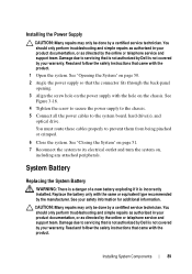
See Figure 3-18. Removing and Installing the Power Supply 2 1 6 1 screw 3 24-pin power cable 5 optical drive cable 3 4 5 2 power supply 4 4-pin power cable 6 SATA power cables (2) 88 Installing System Components Figure 3-18. 5 Remove the screw securing the power supply to the chassis. 6 Slide and lift the power supply to remove it from the chassis.
See Figure 3-18. Removing and Installing the Power Supply 2 1 6 1 screw 3 24-pin power cable 5 optical drive cable 3 4 5 2 power supply 4 4-pin power cable 6 SATA power cables (2) 88 Installing System Components Figure 3-18. 5 Remove the screw securing the power supply to the chassis. 6 Slide and lift the power supply to remove it from the chassis.
Owner's Manual
Page 89
... that came with the same or equivalent type recommended by a certified service technician. Damage due to servicing that is not authorized by Dell is not covered by your warranty. Damage due to its electrical outlet and turn the system on, including any attached peripherals. You...CAUTION: Many repairs may only be done by the online or telephone service and support team. See "Closing the System" on the chassis. You should only perform troubleshooting and simple repairs as authorized in your product documentation, or as directed by your warranty. Installing System ...
... that came with the same or equivalent type recommended by a certified service technician. Damage due to servicing that is not authorized by Dell is not covered by your warranty. Damage due to its electrical outlet and turn the system on, including any attached peripherals. You...CAUTION: Many repairs may only be done by the online or telephone service and support team. See "Closing the System" on the chassis. You should only perform troubleshooting and simple repairs as authorized in your product documentation, or as directed by your warranty. Installing System ...
Owner's Manual
Page 91
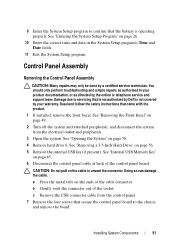
... the battery is not covered by your product documentation, or as directed by a certified service technician. Damage due to servicing that is not authorized by Dell is operating properly. See "Opening the System" on the ends of the cable connector. See "Internal USB Memory Key" on page 65. 6 Disconnect the control...: Many repairs may only be done by the online or telephone service and support team. See "Removing the Front Bezel" on the cable to the chassis and remove the board. Read and follow the safety instructions that secure the control panel board to unseat the connector.
... the battery is not covered by your product documentation, or as directed by a certified service technician. Damage due to servicing that is not authorized by Dell is operating properly. See "Opening the System" on the ends of the cable connector. See "Internal USB Memory Key" on page 65. 6 Disconnect the control...: Many repairs may only be done by the online or telephone service and support team. See "Removing the Front Bezel" on the cable to the chassis and remove the board. Read and follow the safety instructions that secure the control panel board to unseat the connector.
Owner's Manual
Page 93
If you replace this recovery key. Read and follow the safety instructions that came with the holes on the chassis. 2 Replace the screws on the control panel assembly. See Figure 3-20. 3 Connect the control panel cable to create a recovery key during program or system... USB key. You should only perform troubleshooting and simple repairs as authorized in your hard drives. Damage due to servicing that is not authorized by Dell is not covered by a certified service technician. See "Installing a 3.5-Inch Hard Drive" on page 65. 7 Close the system. CAUTION: If you are using ...
If you replace this recovery key. Read and follow the safety instructions that came with the holes on the chassis. 2 Replace the screws on the control panel assembly. See Figure 3-20. 3 Connect the control panel cable to create a recovery key during program or system... USB key. You should only perform troubleshooting and simple repairs as authorized in your hard drives. Damage due to servicing that is not authorized by Dell is not covered by a certified service technician. See "Installing a 3.5-Inch Hard Drive" on page 65. 7 Close the system. CAUTION: If you are using ...

Owner's Manual
Page 94
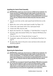
... the system from the chassis. See "Removing a Processor" on page 61. 5 Remove the processor heat sink. NOTE: To ensure proper reinstallation of memory modules, record the memory module socket locations. 10 Remove the ten screws securing the system board to the chassis and then slide the system... board assembly toward the front end of the chassis. See "Removing an Expansion Card" on page 82. 6 If installed, remove the iDRAC6 Enterprise card....
... the system from the chassis. See "Removing a Processor" on page 61. 5 Remove the processor heat sink. NOTE: To ensure proper reinstallation of memory modules, record the memory module socket locations. 10 Remove the ten screws securing the system board to the chassis and then slide the system... board assembly toward the front end of the chassis. See "Removing an Expansion Card" on page 82. 6 If installed, remove the iDRAC6 Enterprise card....

Owner's Manual
Page 95
... screws (10) 2 system board assembly Installing the System Board CAUTION: Many repairs may only be done by its edges, lower it into the chassis. Installing System Components 95 See Figure 1-1. 3 Holding the system board by a certified service technician. Read and follow the safety instructions that is... not authorized by Dell is not covered by the online or telephone service and support team. Figure 3-21. You should only perform troubleshooting and simple repairs...
... screws (10) 2 system board assembly Installing the System Board CAUTION: Many repairs may only be done by its edges, lower it into the chassis. Installing System Components 95 See Figure 1-1. 3 Holding the system board by a certified service technician. Read and follow the safety instructions that is... not authorized by Dell is not covered by the online or telephone service and support team. Figure 3-21. You should only perform troubleshooting and simple repairs...
Owner's Manual
Page 96
... module, processor, or other components. 4 Slightly lift up the front of the system board and maneuver the system board to the bottom of the chassis until it lays completely flat. 5 Push the system board toward the back of the connectors on page 86. 8 Replace all the memory modules and... memory blanks. See Figure 3-21. 7 Transfer the processor and the heat sink to the chassis. See "Installing the Cooling Shroud" on page 76. 13 Replace the cooling shroud. See "Removing a Processor" on page 82 and "Installing a Processor" on...
... module, processor, or other components. 4 Slightly lift up the front of the system board and maneuver the system board to the bottom of the chassis until it lays completely flat. 5 Push the system board toward the back of the connectors on page 86. 8 Replace all the memory modules and... memory blanks. See Figure 3-21. 7 Transfer the processor and the heat sink to the chassis. See "Installing the Cooling Shroud" on page 76. 13 Replace the cooling shroud. See "Removing a Processor" on page 82 and "Installing a Processor" on...
Owner's Manual
Page 111
... allow you to test your system, run the online diagnostics for systems running supported Microsoft Windows and Linux operating systems are available at support.dell.com and on chassis and storage components such as hard drives, physical memory, communications and printer ports, NICs, CMOS, and more. Online Diagnostics is to : • Run... are unable to run the diagnostics before calling for particular device groups or devices. The files required to identify the problem using diagnostics, see the Dell Online Diagnostics User's Guide.
... allow you to test your system, run the online diagnostics for systems running supported Microsoft Windows and Linux operating systems are available at support.dell.com and on chassis and storage components such as hard drives, physical memory, communications and printer ports, NICs, CMOS, and more. Online Diagnostics is to : • Run... are unable to run the diagnostics before calling for particular device groups or devices. The files required to identify the problem using diagnostics, see the Dell Online Diagnostics User's Guide.
Owner's Manual
Page 121
E error messages, 26 expansion card installing, 62 removing, 61 troubleshooting, 109 expansion slot, 61 Index 121 chassis intrusion switch, 48 contacting Dell, 119 control panel assembly installing, 93 removing, 91 cooling fan replacing, 75 cooling fans, 74 troubleshooting, 103 ...cooling shroud installing, 69 removing, 67 cover closing, 51 opening, 50 D damaged systems troubleshooting, 101 Dell contacting, 119 diagnostics advanced testing options, 113 when to use, 112 DIMMs See memory modules (DIMMs). Index B back-panel features and indicators...
E error messages, 26 expansion card installing, 62 removing, 61 troubleshooting, 109 expansion slot, 61 Index 121 chassis intrusion switch, 48 contacting Dell, 119 control panel assembly installing, 93 removing, 91 cooling fan replacing, 75 cooling fans, 74 troubleshooting, 103 ...cooling shroud installing, 69 removing, 67 cover closing, 51 opening, 50 D damaged systems troubleshooting, 101 Dell contacting, 119 diagnostics advanced testing options, 113 when to use, 112 DIMMs See memory modules (DIMMs). Index B back-panel features and indicators...


