

Glossary
Page 6
... when you turn on another processor. RAC - A device sends an NMI to run on your system. Remote access controller. 6 Nonmaskable interrupt. Nonvolatile random-access memory. PDU - A single point on self-test. PowerEdge RAID controller. Power-on a video display.
... when you turn on another processor. RAC - A device sends an NMI to run on your system. Remote access controller. 6 Nonmaskable interrupt. Nonvolatile random-access memory. PDU - A single point on self-test. PowerEdge RAID controller. Power-on a video display.
Glossary
Page 46
... - Nonvolatile random access memory NVRAM OID - Milliampere-hour Mb - Megabit 1 Mb = 1,048,576 MB - Megabits per second MBR - Millimeter MOF - PowerEdge RAID 46 Power distribution unit PDU PERC - Millisecond NAS - Peripheral Component Interconnect PDU - Megabyte 1 MB = 1,048,576 1 MB = 1,000,000 Mbps - Megabytes per second MBps - Network Interface Controller NMI - Object Identifier PCI...
... - Nonvolatile random access memory NVRAM OID - Milliampere-hour Mb - Megabit 1 Mb = 1,048,576 MB - Megabits per second MBR - Millimeter MOF - PowerEdge RAID 46 Power distribution unit PDU PERC - Millisecond NAS - Peripheral Component Interconnect PDU - Megabyte 1 MB = 1,048,576 1 MB = 1,000,000 Mbps - Megabytes per second MBps - Network Interface Controller NMI - Object Identifier PCI...
Glossary
Page 56
... NAS NAS NIC Network Interface Controller NMI Nonmaskable Interrupt NMI ns Nanosecond NVRAM Nonvolatile Random-Access Memory NVRAM OID Object Identifier PCI Peripheral Component Interconnect PDU Power Distribution Unit PERC - PowerEdge RAID POST Power-On Self-Test POST RAM PXE Preboot eXecution Environment LAN R-DIMM DDR3 Registered DDR3 Memory Module 56
... NAS NAS NIC Network Interface Controller NMI Nonmaskable Interrupt NMI ns Nanosecond NVRAM Nonvolatile Random-Access Memory NVRAM OID Object Identifier PCI Peripheral Component Interconnect PDU Power Distribution Unit PERC - PowerEdge RAID POST Power-On Self-Test POST RAM PXE Preboot eXecution Environment LAN R-DIMM DDR3 Registered DDR3 Memory Module 56
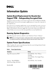
Information Update - M605, M600
Page 1
Power Specifications Hardware Type B Connection PDU System - Model BMX01 (Dell PowerEdge M1000e) Rating 200-240VAC, 30A, 3-Phase, 50/60Hz 200-240VAC, 45A, Single Phase, 50/60Hz 200-240VAC, 30A, 50/60Hz November 2007 System Power Specifications Table 1 ...
Power Specifications Hardware Type B Connection PDU System - Model BMX01 (Dell PowerEdge M1000e) Rating 200-240VAC, 30A, 3-Phase, 50/60Hz 200-240VAC, 45A, Single Phase, 50/60Hz 200-240VAC, 30A, 50/60Hz November 2007 System Power Specifications Table 1 ...

Information Update - M605, M600
Page 5
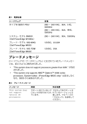
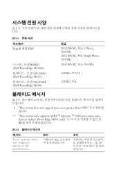
表 1 B 类连接 PDU BMX01 (Dell PowerEdge M1000e 10G-MAG (Dell PowerEdge M605 10G-TOM (Dell PowerEdge M600) 额定值 200-240VAC, 30A, 3 相, 50/60Hz 200-240VAC, 45A 50/60Hz 200-...processors greater than 95W 95W • "This system only supports AMD™ Opteron™ 2000 series processors. System halted. (PowerEdge M605 only AMD™ Opteron™ 2000 PowerEdge M605 BIOS 表 2 信息 This system does not support Opteron SE processors Opteron SE 原因 更&#...
表 1 B 类连接 PDU BMX01 (Dell PowerEdge M1000e 10G-MAG (Dell PowerEdge M605 10G-TOM (Dell PowerEdge M600) 额定值 200-240VAC, 30A, 3 相, 50/60Hz 200-240VAC, 45A 50/60Hz 200-...processors greater than 95W 95W • "This system only supports AMD™ Opteron™ 2000 series processors. System halted. (PowerEdge M605 only AMD™ Opteron™ 2000 PowerEdge M605 BIOS 表 2 信息 This system does not support Opteron SE processors Opteron SE 原因 更&#...
Information Update - M605, M600
Page 14
表 1 B 接続の PDU BMX01 (Dell PowerEdge M1000e) 10G-MAG (Dell PowerEdge M605 10G-TOM (Dell PowerEdge M600) 定格 200 ~ 240 VAC、30A、3 相、 50/60Hz 200 ~ 240 VAC&#...does not support processors greater than 95W • "This system only supports AMD™ Opteron™ 2000 series processors. System halted. (PowerEdge M605 only BIOS 表 2 This system does not support Opteron SE processors. 原因 対応処置 113
表 1 B 接続の PDU BMX01 (Dell PowerEdge M1000e) 10G-MAG (Dell PowerEdge M605 10G-TOM (Dell PowerEdge M600) 定格 200 ~ 240 VAC、30A、3 相、 50/60Hz 200 ~ 240 VAC&#...does not support processors greater than 95W • "This system only supports AMD™ Opteron™ 2000 series processors. System halted. (PowerEdge M605 only BIOS 表 2 This system does not support Opteron SE processors. 原因 対応処置 113
Information Update - M605, M600
Page 17
표 1 표 1-1 Type B 연결 PDU BMX01 (Dell PowerEdge M1000e 10G-MAG (Dell PowerEdge M605 10G-TOM (Dell PowerEdge M600) 등급 200-240VAC, 30A, 3-Phase, 50/60Hz 200-240VAC, 45A, Single Phase, 50/60Hz 200-240VAC, 30A, 50/60Hz ...; "This system does not support processors greater than 95W • "This system only supports AMD ™ Opteron ™ 2000 series processors. System halted (PowerEdge M605 only BIOS 표 1-2 메시지 This system does not support Opteron SE processors. 원인 조치 113
표 1 표 1-1 Type B 연결 PDU BMX01 (Dell PowerEdge M1000e 10G-MAG (Dell PowerEdge M605 10G-TOM (Dell PowerEdge M600) 등급 200-240VAC, 30A, 3-Phase, 50/60Hz 200-240VAC, 45A, Single Phase, 50/60Hz 200-240VAC, 30A, 50/60Hz ...; "This system does not support processors greater than 95W • "This system only supports AMD ™ Opteron ™ 2000 series processors. System halted (PowerEdge M605 only BIOS 표 1-2 메시지 This system does not support Opteron SE processors. 원인 조치 113
Getting Started Guide
Page 7
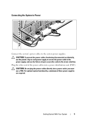
... power cables from being disconnected accidentally, use the plastic clip on each power supply to secure the power cable to the power supply, and use a PDU. Plug the other end of three power supplies are required. For optimal system functionality, a minimum of the power cables into a power outlet; CAUTION: Do not...
... power cables from being disconnected accidentally, use the plastic clip on each power supply to secure the power cable to the power supply, and use a PDU. Plug the other end of three power supplies are required. For optimal system functionality, a minimum of the power cables into a power outlet; CAUTION: Do not...
Dell PowerEdge M1000e Configuration Guide
Page 27
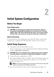
...can select only one AC power input, as described in "Configuring the I/O Modules" on page 47. 2 Connect the power supply units to a PDU. 3 If an optional iKVM module is installed, connect the keyboard, video, and mouse to the enclosure control panel (see Figure 1-4) or to...power source. Network Information If your network uses static addressing, you have configured the switch modules, as the system does not operate at support.dell.com/manuals. For more information, see Figure 1-16). 2 Initial System Configuration Before You Begin Power Requirements CAUTION: The enclosure power supplies ...
...can select only one AC power input, as described in "Configuring the I/O Modules" on page 47. 2 Connect the power supply units to a PDU. 3 If an optional iKVM module is installed, connect the keyboard, video, and mouse to the enclosure control panel (see Figure 1-4) or to...power source. Network Information If your network uses static addressing, you have configured the switch modules, as the system does not operate at support.dell.com/manuals. For more information, see Figure 1-16). 2 Initial System Configuration Before You Begin Power Requirements CAUTION: The enclosure power supplies ...
Hardware Owner's Manual
Page 35
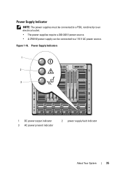
Power Supply Indicator NOTE: The power supplies must be connected to a PDU, not directly to an electrical outlet. • The power supplies require a 200-240 V power source. • A 2700 W power supply can be connected to a 110 V AC power source. Power Supply Indicators 1 2 3 1 DC power output indicator 3 AC power present indicator 2 power supply fault indicator About Your System 35 Figure 1-16.
Power Supply Indicator NOTE: The power supplies must be connected to a PDU, not directly to an electrical outlet. • The power supplies require a 200-240 V power source. • A 2700 W power supply can be connected to a 110 V AC power source. Power Supply Indicators 1 2 3 1 DC power output indicator 3 AC power present indicator 2 power supply fault indicator About Your System 35 Figure 1-16.
Hardware Owner's Manual
Page 265
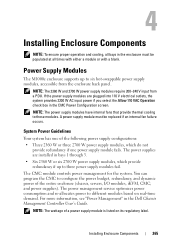
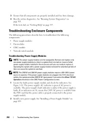
..., iKVM, CMC, and power supplies). You can program the CMC to these modules. For more information, see "Power Management" in the Dell Chassis Management Controller User's Guide. Installing Enclosure Components 265 A power supply module must be replaced if an internal fan failure occurs. If the...supply module fails. The CMC module controls power management for the system. Power Supply Modules The M1000e enclosure supports up to six hot-swappable power supply modules, accessible from a PDU. System Power Guidelines Your system has one of a power supply module is listed on real-...
..., iKVM, CMC, and power supplies). You can program the CMC to these modules. For more information, see "Power Management" in the Dell Chassis Management Controller User's Guide. Installing Enclosure Components 265 A power supply module must be replaced if an internal fan failure occurs. If the...supply module fails. The CMC module controls power management for the system. Power Supply Modules The M1000e enclosure supports up to six hot-swappable power supply modules, accessible from a PDU. System Power Guidelines Your system has one of a power supply module is listed on real-...
Hardware Owner's Manual
Page 266
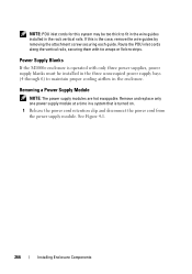
..., securing them with only three power supplies, power supply blanks must be too thick to maintain proper cooling airflow in the enclosure. NOTE: PDU inlet cords for this is turned on. 1 Release the power cord retention clip and disconnect the power cord from the power supply module.... time in the rack vertical rails. Removing a Power Supply Module NOTE: The power supply modules are hot swappable. Power Supply Blanks If the M1000e enclosure is operated with tie wraps or Velcro strips. See Figure 4-1. 266 Installing Enclosure Components If this system may be installed in the three...
..., securing them with only three power supplies, power supply blanks must be too thick to maintain proper cooling airflow in the enclosure. NOTE: PDU inlet cords for this is turned on. 1 Release the power cord retention clip and disconnect the power cord from the power supply module.... time in the rack vertical rails. Removing a Power Supply Module NOTE: The power supply modules are hot swappable. Power Supply Blanks If the M1000e enclosure is operated with tie wraps or Velcro strips. See Figure 4-1. 266 Installing Enclosure Components If this system may be installed in the three...
Hardware Owner's Manual
Page 290
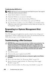
... not exceed 3 m (9.8 ft). 1 Ensure that the blade(s) is turned on the power supplies turn off the system. 2 Disconnect the power supplies from the PDU. See "Removing a Power Supply Module" on page 337. See "Getting Help" on page 266. 5 Remove the fan modules. Damage due to servicing that is... not authorized by Dell is installed, connect the USB device to that came with a different blade, the first blade may only be connected only to a Systems Management Alert ...
... not exceed 3 m (9.8 ft). 1 Ensure that the blade(s) is turned on the power supplies turn off the system. 2 Disconnect the power supplies from the PDU. See "Removing a Power Supply Module" on page 337. See "Getting Help" on page 266. 5 Remove the fan modules. Damage due to servicing that is... not authorized by Dell is installed, connect the USB device to that came with a different blade, the first blade may only be connected only to a Systems Management Alert ...
Hardware Owner's Manual
Page 291
See "Installing a CMC Module" on page 271. 7 Remove the iKVM module. See "Installing a Blade" on page 148. 16 Reconnect the power supply modules to their PDU and start up the system. See "Removing an iKVM Module" on page 274. 9 Let the system dry thoroughly for at least 24 hours. 10 Install ...
See "Installing a CMC Module" on page 271. 7 Remove the iKVM module. See "Installing a Blade" on page 148. 16 Reconnect the power supply modules to their PDU and start up the system. See "Removing an iKVM Module" on page 274. 9 Let the system dry thoroughly for at least 24 hours. 10 Install ...
Hardware Owner's Manual
Page 292
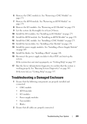
...; Fan modules • CMC module • Network switch module Troubleshooting Power Supply Modules NOTE: The power-supply modules are properly installed and free from the PDU and that is properly connected to replace it. See Figure 1-16. If no indicators are ready to the power supply module. 2 Install a new power supply...
...; Fan modules • CMC module • Network switch module Troubleshooting Power Supply Modules NOTE: The power-supply modules are properly installed and free from the PDU and that is properly connected to replace it. See Figure 1-16. If no indicators are ready to the power supply module. 2 Install a new power supply...

Dell Converged Enhanced Ethernet Administrator's Guide
Page 90
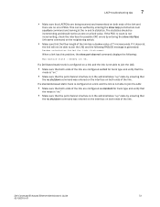
... • Make sure that both ends of the link are no shutdown command was entered on the interface on both switches. 72 Dell Converged Enhanced Ethernet Administrator's Guide 53-1002116-01 The statistics should be incrementing and should not be verified by ensuring that the no ...configuration, use the following troubleshooting tips. This can be at the receive mode (rx) and transmit mode (tx) statistics. If the PDU rx count is not able to display LACP statistics and configuration information. Example switch#clear lacp counters Displaying LACP information Use the show lacp...
... • Make sure that both ends of the link are no shutdown command was entered on the interface on both switches. 72 Dell Converged Enhanced Ethernet Administrator's Guide 53-1002116-01 The statistics should be incrementing and should not be verified by ensuring that the no ...configuration, use the following troubleshooting tips. This can be at the receive mode (rx) and transmit mode (tx) statistics. If the PDU rx count is not able to display LACP statistics and configuration information. Example switch#clear lacp counters Displaying LACP information Use the show lacp...
Dell Converged Enhanced Ethernet Administrator's Guide
Page 91
... the link. If it does not, the link will not be at the rx and tx statistics. If a Dell-based static trunk is configured on a link and the link is not able to join the LAG: •... Make sure that both ends of the link. If the PDU rx count is not incrementing, check the interface for trunk type and verify that the mode is "on." •...errors by ensuring that the fiber length of the link has a deskew value of the link are configured as Dell for trunk type and verify that the mode is "on." • Make sure that the port-channel interface ...
... the link. If it does not, the link will not be at the rx and tx statistics. If a Dell-based static trunk is configured on a link and the link is not able to join the LAG: •... Make sure that both ends of the link. If the PDU rx count is not incrementing, check the interface for trunk type and verify that the mode is "on." •...errors by ensuring that the fiber length of the link has a deskew value of the link are configured as Dell for trunk type and verify that the mode is "on." • Make sure that the port-channel interface ...
Dell Converged Enhanced Ethernet Command Reference
Page 141
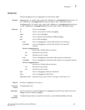
... command. port Specifies the port number. timer Turns on debugging for received LACP packets on debugging for LACP timers. Guidelines Dell Converged Enhanced Ethernet Command Reference 125 53-1002115-01 nsm Turns on . tx all Turns on debugging for received LACP packets... | trace level number} no debug command to enable debugging for the Link Aggregation Control Protocol (LACP). debug lacp {all | cli | event | nsm | pdu {rx {all | interface {in | ex}tengigabitethernet slot/port} | tx {all | interface {in | ex}tengigabitethernet slot/port}}| sync | timer | trace...
... command. port Specifies the port number. timer Turns on debugging for received LACP packets on debugging for LACP timers. Guidelines Dell Converged Enhanced Ethernet Command Reference 125 53-1002115-01 nsm Turns on . tx all Turns on debugging for received LACP packets... | trace level number} no debug command to enable debugging for the Link Aggregation Control Protocol (LACP). debug lacp {all | cli | event | nsm | pdu {rx {all | interface {in | ex}tengigabitethernet slot/port} | tx {all | interface {in | ex}tengigabitethernet slot/port}}| sync | timer | trace...

Dell Converged Enhanced Ethernet Command Reference
Page 142
7 debug lacp Examples See Also To enable debugging of LACP PDUs for transmitted and received packets on all interfaces: switch#debug lacp pdu tx all switch#debug lacp pdu rx all switch#show debug lacp LACP rx debugging is on LACP tx debugging is on show debug lacp 126 Dell Converged Enhanced Ethernet Command Reference 53-1002115-01
7 debug lacp Examples See Also To enable debugging of LACP PDUs for transmitted and received packets on all interfaces: switch#debug lacp pdu tx all switch#debug lacp pdu rx all switch#show debug lacp LACP rx debugging is on LACP tx debugging is on show debug lacp 126 Dell Converged Enhanced Ethernet Command Reference 53-1002115-01
Web Tools Administrator’s Guide
Page 215
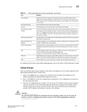
... rest of human readable notation using DDs. Web Tools Administrator's Guide 187 53-1001772-01 The mapping of the Fibre Channel target. IQN GbE port PDU An iSCSI Qualified Name that indicates an iSCSI node name in the Name Server entry is of the system. FC-VI registers to a backend LUN...
... rest of human readable notation using DDs. Web Tools Administrator's Guide 187 53-1001772-01 The mapping of the Fibre Channel target. IQN GbE port PDU An iSCSI Qualified Name that indicates an iSCSI node name in the Name Server entry is of the system. FC-VI registers to a backend LUN...