Getting Started Guide
Page 5
...upgradable to two internal, 1-inch high optional Serial-Attached SCSI (SAS) hard drives with an optional SAS controller card. • Optional remote access controller for the following internal hard-drive configurations: - One full-height, half...SATA hard drives with a x4 lane capability. - One Intel Celeron® D, 300 Sequence - This option requires a riser card with support for PCI-X and PCIe RAC connectors. • Optional USB flash drive emulates a diskette drive or hard drive. • One 345... Features The major hardware and software features of the following riser card options: -
...upgradable to two internal, 1-inch high optional Serial-Attached SCSI (SAS) hard drives with an optional SAS controller card. • Optional remote access controller for the following internal hard-drive configurations: - One full-height, half...SATA hard drives with a x4 lane capability. - One Intel Celeron® D, 300 Sequence - This option requires a riser card with support for PCI-X and PCIe RAC connectors. • Optional USB flash drive emulates a diskette drive or hard drive. • One 345... Features The major hardware and software features of the following riser card options: -
Getting Started Guide
Page 11
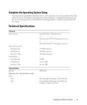
...Celeron D Intel Pentium 4 Intel Core 2 Duo Internal cache Intel Celeron D Intel Pentium 4 Intel Core 2 Duo Expansion Buses Bus type Expansion slots - Two optional riser cards Riser 1 PCIe PCIe One Intel® Core™ 2 Duo processor or One Intel Celeron® D, 300 Sequence processor or One Intel Pentium® 4, 600 Sequence... processor 533 MHz minimum 800 MHz minimum 1066 MHz minimum 256 KB at least 2 MB at least 2 MB PCI-X, PCIe One full-height, half-length, x8 lane PCIe slot One full-height, half-length x4 lane PCIe slot residing on a x8 lane ...
...Celeron D Intel Pentium 4 Intel Core 2 Duo Internal cache Intel Celeron D Intel Pentium 4 Intel Core 2 Duo Expansion Buses Bus type Expansion slots - Two optional riser cards Riser 1 PCIe PCIe One Intel® Core™ 2 Duo processor or One Intel Celeron® D, 300 Sequence processor or One Intel Pentium® 4, 600 Sequence... processor 533 MHz minimum 800 MHz minimum 1066 MHz minimum 256 KB at least 2 MB at least 2 MB PCI-X, PCIe One full-height, half-length, x8 lane PCIe slot One full-height, half-length x4 lane PCIe slot residing on a x8 lane ...
Getting Started Guide
Page 12
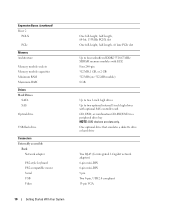
...mini-DIN 6-pin mini-DIN 9 pin Two 4-pin, USB 2.0 compliant 15-pin VGA Expansion Buses (continued) Riser 2 PCI-X PCIe Memory Architecture Memory module sockets Memory module capacities Minimum RAM Maximum RAM Drives Hard Drives SATA SAS Optical ... USB Video 10 Getting Started With Your System One full-height, half-length, 64-bit, 133MHz PCI-X slot One full-height, half-length, x8 lane PCIe slot Up to four unbuffered DDR2 533/... two optional internal 1-inch high drives with optional SAS controller card CD, DVD, or combination CD-RW/DVD in a peripheral drive bay NOTE: DVD devices are data only.
...mini-DIN 6-pin mini-DIN 9 pin Two 4-pin, USB 2.0 compliant 15-pin VGA Expansion Buses (continued) Riser 2 PCI-X PCIe Memory Architecture Memory module sockets Memory module capacities Minimum RAM Maximum RAM Drives Hard Drives SATA SAS Optical ... USB Video 10 Getting Started With Your System One full-height, half-length, 64-bit, 133MHz PCI-X slot One full-height, half-length, x8 lane PCIe slot Up to four unbuffered DDR2 533/... two optional internal 1-inch high drives with optional SAS controller card CD, DVD, or combination CD-RW/DVD in a peripheral drive bay NOTE: DVD devices are data only.
Hardware Owner's Manual (PDF)
Page 43
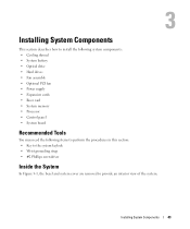
... the following system components: • Cooling shroud • System battery • Optical drive • Hard drives • Fan assembly • Optional PCI fan • Power supply • Expansion cards • Riser card • System memory • Processor • Control panel • System board Recommended Tools You may need the following items to perform the...
... the following system components: • Cooling shroud • System battery • Optical drive • Hard drives • Fan assembly • Optional PCI fan • Power supply • Expansion cards • Riser card • System memory • Processor • Control panel • System board Recommended Tools You may need the following items to perform the...
Hardware Owner's Manual (PDF)
Page 44
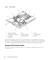
...Inside the System 2 1 4 3 5 6 7 10 8 9 1 optical drive (optional) 2 4 PCI expansion card (optional) 5 7 power supply 8 10 hard drive 0 PCI fan processor and heat sink processor fan module 3 riser card 6 memory modules (4) 9 hard drive 1 The system board holds the system's control circuitry and other electronic components...the System The system is supplied to two hard drives and an optional optical drive. Using a riser card, the system can accommodate two expansion cards. The processor and memory are installed directly on the system board. To upgrade or troubleshoot the ...
...Inside the System 2 1 4 3 5 6 7 10 8 9 1 optical drive (optional) 2 4 PCI expansion card (optional) 5 7 power supply 8 10 hard drive 0 PCI fan processor and heat sink processor fan module 3 riser card 6 memory modules (4) 9 hard drive 1 The system board holds the system's control circuitry and other electronic components...the System The system is supplied to two hard drives and an optional optical drive. Using a riser card, the system can accommodate two expansion cards. The processor and memory are installed directly on the system board. To upgrade or troubleshoot the ...
Hardware Owner's Manual (PDF)
Page 63
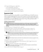
...internal connectors. If you are authorized to remove the system cover and access any of a PCI-X/PCIe riser card. See Figure 3-14. 7 Slide the expansion-card sliding retainer to the expansion card. See Figure 3-15. 8 Connect any procedure, see your Product Information Guide for the ...external cable(s) to the closed position so that the expansion-card bracket is available with an optional PCIe riser card or PCI-X/PCIe riser card. Filler brackets must be installed over empty expansion card slots to install certain expansion cards with x8-lane connectors-slot 1 has x4-lane capability ...
...internal connectors. If you are authorized to remove the system cover and access any of a PCI-X/PCIe riser card. See Figure 3-14. 7 Slide the expansion-card sliding retainer to the expansion card. See Figure 3-15. 8 Connect any procedure, see your Product Information Guide for the ...external cable(s) to the closed position so that the expansion-card bracket is available with an optional PCIe riser card or PCI-X/PCIe riser card. Filler brackets must be installed over empty expansion card slots to install certain expansion cards with x8-lane connectors-slot 1 has x4-lane capability ...

Hardware Owner's Manual (PDF)
Page 75
...your Product Information Guide for complete information about safety precautions, working inside the system. See "Replacing the Processor" on the riser card. See Figure 6-2. 8 Remove all PCI expansion cards installed on page 71. 4 Remove the memory modules. See Figure 3-21. 14 Lay the system board tray down on... page 47. 3 Remove the heat sink and processor. See "Removing the Riser Card" on page 66. 10 Disconnect the chassis ...
...your Product Information Guide for complete information about safety precautions, working inside the system. See "Replacing the Processor" on the riser card. See Figure 6-2. 8 Remove all PCI expansion cards installed on page 71. 4 Remove the memory modules. See Figure 3-21. 14 Lay the system board tray down on... page 47. 3 Remove the heat sink and processor. See "Removing the Riser Card" on page 66. 10 Disconnect the chassis ...

Hardware Owner's Manual (PDF)
Page 77
.... 11 Install the processor and heat sink. See "Installing the Riser Card" on page 67. 8 Using a #2 Phillips screwdriver, tighten the two screws that secure the riser card to the system board. 9 Install any PCI expansion cards that you installed a SAS controller, reconnect the interface cable to... the IDE connector on the system card. See Figure 6-2 for the location of the IDE connector. 15...
.... 11 Install the processor and heat sink. See "Installing the Riser Card" on page 67. 8 Using a #2 Phillips screwdriver, tighten the two screws that secure the riser card to the system board. 9 Install any PCI expansion cards that you installed a SAS controller, reconnect the interface cable to... the IDE connector on the system card. See Figure 6-2 for the location of the IDE connector. 15...
Hardware Owner's Manual (PDF)
Page 99
... connector (expansion controller) Connector for the location and description of the expansion-card slots on the two riser cards. See Figure 6-3 and Figure 6-4 for the chassis intrusion switch Remote access controller connector Remote access controller connector Riser card interface connector Riser Card Connectors The system is available with either a PCIe riser card or a PCI-X/PCIe riser card. Table 6-2. Jumpers and Connectors 99
... connector (expansion controller) Connector for the location and description of the expansion-card slots on the two riser cards. See Figure 6-3 and Figure 6-4 for the chassis intrusion switch Remote access controller connector Remote access controller connector Riser card interface connector Riser Card Connectors The system is available with either a PCIe riser card or a PCI-X/PCIe riser card. Table 6-2. Jumpers and Connectors 99
Hardware Owner's Manual (PDF)
Page 100
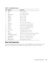
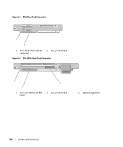
PCI-X/PCIe Riser Card Connectors 1 3 2 1 slot 1, PCI-X 64-bit 133 MHz (3.3 V) 2 slot 2, PCIe x8-lane 3 system management 100 Jumpers and Connectors Figure 6-3. PCIe Riser Card Connectors 1 2 1 slot 1, PCIe x4-lane (x8-lane connector) 2 slot 2, PCIe x8-lane Figure 6-4.
PCI-X/PCIe Riser Card Connectors 1 3 2 1 slot 1, PCI-X 64-bit 133 MHz (3.3 V) 2 slot 2, PCIe x8-lane 3 system management 100 Jumpers and Connectors Figure 6-3. PCIe Riser Card Connectors 1 2 1 slot 1, PCIe x4-lane (x8-lane connector) 2 slot 2, PCIe x8-lane Figure 6-4.

Hardware Owner's Manual (PDF)
Page 137
...riser card, 99 system board, 98 Console Redirection screen, 35 control panel installing, 74 removing, 73 cooling fan troubleshooting, 87 cooling shroud installing, 48 removing, 47 cover closing, 47 opening, 46 CPU Information screen, 33 D damaged systems troubleshooting, 85 Dell contacting, 108 Dell PowerEdge... partition, 94 using Dell PowerEdge Diagnostics, 93 when to use, 94 diagnostics indicator codes, 22 drives CD, 50 optical, 50 E error messages, 29 expansion cards installing, 63 removing, 65 troubleshooting, 91 external devices connecting, 14 F fan assembly (PCI) installing, 60 removing...
...riser card, 99 system board, 98 Console Redirection screen, 35 control panel installing, 74 removing, 73 cooling fan troubleshooting, 87 cooling shroud installing, 48 removing, 47 cover closing, 47 opening, 46 CPU Information screen, 33 D damaged systems troubleshooting, 85 Dell contacting, 108 Dell PowerEdge... partition, 94 using Dell PowerEdge Diagnostics, 93 when to use, 94 diagnostics indicator codes, 22 drives CD, 50 optical, 50 E error messages, 29 expansion cards installing, 63 removing, 65 troubleshooting, 91 external devices connecting, 14 F fan assembly (PCI) installing, 60 removing...

Hardware Owner's Manual (PDF)
Page 138
..., 45 CD drive, 51 control panel, 74 cooling shroud, 48 expansion cards, 63 hard drives, 56 memory modules, 69 optical drive, 51 PCI fan assembly, 60 power supply, 62 processor fan assembly, 58 riser card, 67 system board, 76 Integrated Devices screen, 34 IRQs avoiding conflicts,... setup program, 30 NICs indicators, 15 troubleshooting, 83 NMI button, 13 O optical drive installing, 51 removing, 50 P password disabling, 101 PCI fan assembly installing, 60 removing, 59 troubleshooting, 87 POST accessing system features, 10 power supply installing, 62 removing, 61 troubleshooting, 86 processor ...
..., 45 CD drive, 51 control panel, 74 cooling shroud, 48 expansion cards, 63 hard drives, 56 memory modules, 69 optical drive, 51 PCI fan assembly, 60 power supply, 62 processor fan assembly, 58 riser card, 67 system board, 76 Integrated Devices screen, 34 IRQs avoiding conflicts,... setup program, 30 NICs indicators, 15 troubleshooting, 83 NMI button, 13 O optical drive installing, 51 removing, 50 P password disabling, 101 PCI fan assembly installing, 60 removing, 59 troubleshooting, 87 POST accessing system features, 10 power supply installing, 62 removing, 61 troubleshooting, 86 processor ...

Hardware Owner's Manual (PDF)
Page 139
... 73 cooling shroud, 47 expansion cards, 65 hard drives, 52 memory modules, 70 optical drive, 50 PCI fan assembly, 59 power supply, 61 processor fan assembly, 57 riser card, 66 system board, 75 replacing processor, 71 system battery, 49 riser card connectors, 99 installing, 67 removing,... 66 S safety, 79 SAS controller card. securing your system, 38 serial I/O device troubleshooting, 82 setup password assigning, 39 changing, 40 features, 37 working with, 40 startup accessing system features, 10 support contacting Dell, 108 ...
... 73 cooling shroud, 47 expansion cards, 65 hard drives, 52 memory modules, 70 optical drive, 50 PCI fan assembly, 59 power supply, 61 processor fan assembly, 57 riser card, 66 system board, 75 replacing processor, 71 system battery, 49 riser card connectors, 99 installing, 67 removing,... 66 S safety, 79 SAS controller card. securing your system, 38 serial I/O device troubleshooting, 82 setup password assigning, 39 changing, 40 features, 37 working with, 40 startup accessing system features, 10 support contacting Dell, 108 ...

Information Update
Page 2
... 3.0 V coin battery connector SATA 0 hard drive connector SATA 1 hard drive connector PCI fan connector Control panel interface connector Optical drive interface connector Hard drive activity connector (expansion...system password if the Password Status field is enabled for the chassis intrusion switch Riser card interface connector Using the Setup Password When a setup password is set to ... program for the system password. Trademarks used in this text: Dell and the DELL logo are trademarks of Dell Inc. Dell Inc. Printed in this document is strictly forbidden. Table 1....
... 3.0 V coin battery connector SATA 0 hard drive connector SATA 1 hard drive connector PCI fan connector Control panel interface connector Optical drive interface connector Hard drive activity connector (expansion...system password if the Password Status field is enabled for the chassis intrusion switch Riser card interface connector Using the Setup Password When a setup password is set to ... program for the system password. Trademarks used in this text: Dell and the DELL logo are trademarks of Dell Inc. Dell Inc. Printed in this document is strictly forbidden. Table 1....

