Information Update - Dell OpenManage™ Server Support Kit Version 4.3 (.pdf)
Page 1
... Dell is unplugged from its AC power source before installing the DRAC 4/P card. 2 Open the system. Your system's Product Information Guide provides a sequence of safety steps that the system is not covered by the online or telephone service and support team. September 2004 You should be damaged if it from its AC power supply...
... Dell is unplugged from its AC power source before installing the DRAC 4/P card. 2 Open the system. Your system's Product Information Guide provides a sequence of safety steps that the system is not covered by the online or telephone service and support team. September 2004 You should be damaged if it from its AC power supply...
Getting Started Guide
Page 5
... a peripheral drive bay. • Support for PCI-X and PCIe RAC connectors. • Optional USB flash drive emulates a diskette drive or hard drive. • One 345-W power supply. • Two integrated Gigabit Ethernet network adapters, capable of supporting 10-Mbps, 100-Mbps, and 1000-Mbps data rates. This option requires a riser card with...
... a peripheral drive bay. • Support for PCI-X and PCIe RAC connectors. • Optional USB flash drive emulates a diskette drive or hard drive. • One 345-W power supply. • Two integrated Gigabit Ethernet network adapters, capable of supporting 10-Mbps, 100-Mbps, and 1000-Mbps data rates. This option requires a riser card with...
Getting Started Guide
Page 6
...provide documentation and tools for configuring and managing your system. 4 Getting Started With Your System • Two system cooling fans, one power-supply cooling fan, and one optional PCI fan for systems with a SAS/RAID controller. • Serial connector for console redirection support...., including chassis-intrusion detection and keylock on the optional bezel. • Systems management circuitry that came with your system or on support.dell.com. • CDs included with the systems management software. • Back-panel connectors include keyboard, video, mouse, serial, two ...
...provide documentation and tools for configuring and managing your system. 4 Getting Started With Your System • Two system cooling fans, one power-supply cooling fan, and one optional PCI fan for systems with a SAS/RAID controller. • Serial connector for console redirection support...., including chassis-intrusion detection and keylock on the optional bezel. • Systems management circuitry that came with your system or on support.dell.com. • CDs included with the systems management software. • Back-panel connectors include keyboard, video, mouse, serial, two ...

Getting Started Guide
Page 9
Connecting the Keyboard, Mouse, and Monitor Connect the keyboard, mouse, and monitor (optional). Connecting the Power Connect the system's power cable(s) to tighten the screws (if any) on the back of your system have icons indicating which cable to the back of ... grounded electrical outlet or a separate power source such as shown, and close the clip. Be sure to the system. Getting Started With Your System 7 Plug the other end of the system, run the cable through the cable retention clip as an uninterrupted power supply (UPS) or a power distribution unit (PDU). The connectors...
Connecting the Keyboard, Mouse, and Monitor Connect the keyboard, mouse, and monitor (optional). Connecting the Power Connect the system's power cable(s) to tighten the screws (if any) on the back of your system have icons indicating which cable to the back of ... grounded electrical outlet or a separate power source such as shown, and close the clip. Be sure to the system. Getting Started With Your System 7 Plug the other end of the system, run the cable through the cable retention clip as an uninterrupted power supply (UPS) or a power distribution unit (PDU). The connectors...
Getting Started Guide
Page 13
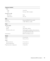
... (26 lb) Getting Started With Your System 11 Connectors (continued) Front Video USB Internally accessible IDE channel SATA channels Video Video type Video memory Power AC power supply Wattage Voltage Maximum inrush current System battery Physical Height Width Depth With optional bezel Without optional bezel Weight (maximum configuration) 15-pin VGA Two 4-pin...
... (26 lb) Getting Started With Your System 11 Connectors (continued) Front Video USB Internally accessible IDE channel SATA channels Video Video type Video memory Power AC power supply Wattage Voltage Maximum inrush current System battery Physical Height Width Depth With optional bezel Without optional bezel Weight (maximum configuration) 15-pin VGA Two 4-pin...
Hardware Owner's Manual (PDF)
Page 5
Power Supply 61 Removing the Power Supply 61 Installing the Power Supply 62 Expansion Cards 63 Installing an Expansion Card 63 Removing an Expansion Card 65 Riser Card 66 Removing the Riser Card 66 Installing the Riser ...
Power Supply 61 Removing the Power Supply 61 Installing the Power Supply 62 Expansion Cards 63 Installing an Expansion Card 63 Removing an Expansion Card 65 Riser Card 66 Removing the Riser Card 66 Installing the Riser ...
Hardware Owner's Manual (PDF)
Page 6
... Troubleshooting the System Battery 86 Troubleshooting the Power Supply 86 Troubleshooting System Cooling Problems 87 Troubleshooting a Fan 87 Troubleshooting System Memory 88 Troubleshooting an Optical Drive 89 Troubleshooting a Hard Drive 90 Troubleshooting Expansion Cards 91 Troubleshooting the Microprocessor 92 5 Running the System Diagnostics 93 Using Dell PowerEdge Diagnostics 93 System Diagnostics Features 93 When...
... Troubleshooting the System Battery 86 Troubleshooting the Power Supply 86 Troubleshooting System Cooling Problems 87 Troubleshooting a Fan 87 Troubleshooting System Memory 88 Troubleshooting an Optical Drive 89 Troubleshooting a Hard Drive 90 Troubleshooting Expansion Cards 91 Troubleshooting the Microprocessor 92 5 Running the System Diagnostics 93 Using Dell PowerEdge Diagnostics 93 System Diagnostics Features 93 When...

Hardware Owner's Manual (PDF)
Page 14
... and Indicators Figure 1-2 shows the controls, indicators, and connectors located on the system's back panel. Back-Panel Features and Indicators 1 23 4 5 6 7 89 10 12 11 1 power supply connector 4 USB connectors (2) 7 video connector 10 expansion slots (2) 2 keyboard connector 5 Kensington lock 8 NIC1 connector 11 system status indicator 3 mouse connector 6 serial connector 9 NIC2 connector 12...
... and Indicators Figure 1-2 shows the controls, indicators, and connectors located on the system's back panel. Back-Panel Features and Indicators 1 23 4 5 6 7 89 10 12 11 1 power supply connector 4 USB connectors (2) 7 video connector 10 expansion slots (2) 2 keyboard connector 5 Kensington lock 8 NIC1 connector 11 system status indicator 3 mouse connector 6 serial connector 9 NIC2 connector 12...
Hardware Owner's Manual (PDF)
Page 43
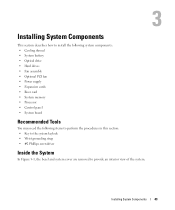
... install the following system components: • Cooling shroud • System battery • Optical drive • Hard drives • Fan assembly • Optional PCI fan • Power supply • Expansion cards • Riser card • System memory • Processor • Control panel • System board Recommended Tools You may need the following items...
... install the following system components: • Cooling shroud • System battery • Optical drive • Hard drives • Fan assembly • Optional PCI fan • Power supply • Expansion cards • Riser card • System memory • Processor • Control panel • System board Recommended Tools You may need the following items...
Hardware Owner's Manual (PDF)
Page 44
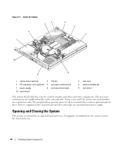
... and cover. 44 Installing System Components The peripheral bays provide space for up to the system board and drives through one nonredundant power supply. Opening and Closing the System The system is supplied to two hard drives and an optional optical drive. Inside the System 2 1 4 3 5 6 7 10 8 9 1 optical drive (optional) 2 4 PCI expansion card (optional...
... and cover. 44 Installing System Components The peripheral bays provide space for up to the system board and drives through one nonredundant power supply. Opening and Closing the System The system is supplied to two hard drives and an optional optical drive. Inside the System 2 1 4 3 5 6 7 10 8 9 1 optical drive (optional) 2 4 PCI expansion card (optional...

Hardware Owner's Manual (PDF)
Page 61
...authorized to remove the system cover and access any procedure, see your Product Information Guide for the location of the power supply that secures the power supply to the FP_CONN1 connector on the system board. See Figure 6-2 for complete information about safety precautions, working inside ...the system. Installing System Components 61 See "Closing the System" on page 46. 2 Disconnect the following power supply cables: a P3 from the hard drive cable harness b P2 from system board connector 12V c P1 from the chassis. 6 Connect the...
...authorized to remove the system cover and access any procedure, see your Product Information Guide for the location of the power supply that secures the power supply to the FP_CONN1 connector on the system board. See Figure 6-2 for complete information about safety precautions, working inside ...the system. Installing System Components 61 See "Closing the System" on page 46. 2 Disconnect the following power supply cables: a P3 from the hard drive cable harness b P2 from system board connector 12V c P1 from the chassis. 6 Connect the...

Hardware Owner's Manual (PDF)
Page 62
Figure 3-13. Installing and Removing the Power Supply 3 2 1 4 5 7 6 1 screw 4 power supply 7 P3 connector 2 P1 connector 5 pins (4) 3 P2 connector 6 securing brackets (4) Installing the Power Supply 1 Lower the power supply into the chassis and slide it backward until the four pins on the power supply are engaged into the securing brackets. 2 Using a #2 Phillips screwdriver, install the screw at the front of the power supply that secures the power supply to the chassis. 62 Installing System Components
Figure 3-13. Installing and Removing the Power Supply 3 2 1 4 5 7 6 1 screw 4 power supply 7 P3 connector 2 P1 connector 5 pins (4) 3 P2 connector 6 securing brackets (4) Installing the Power Supply 1 Lower the power supply into the chassis and slide it backward until the four pins on the power supply are engaged into the securing brackets. 2 Using a #2 Phillips screwdriver, install the screw at the front of the power supply that secures the power supply to the chassis. 62 Installing System Components
Hardware Owner's Manual (PDF)
Page 63
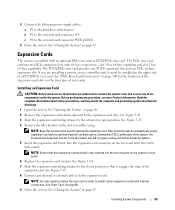
... available with x8-lane connectors-slot 1 has x4-lane capability and slot 2 has x8-lane capability. See "Riser Card" on page 47. 3 Connect the following power supply cables: a P3 to the hard drive cable harness b P2 to the system board connector 12V c P1 to the retracted or open position. Installing System Components...
... available with x8-lane connectors-slot 1 has x4-lane capability and slot 2 has x8-lane capability. See "Riser Card" on page 47. 3 Connect the following power supply cables: a P3 to the hard drive cable harness b P2 to the system board connector 12V c P1 to the retracted or open position. Installing System Components...

Hardware Owner's Manual (PDF)
Page 67
... inside the computer and protecting against electrostatic discharge. 1 Insert the riser card firmly into the riser card connector on the system board adjacent to the power supply and can accommodate 512 MB to remove the system cover and access any expansion card(s). See "Installing an Expansion Card" on page 47.
... inside the computer and protecting against electrostatic discharge. 1 Insert the riser card firmly into the riser card connector on the system board adjacent to the power supply and can accommodate 512 MB to remove the system cover and access any expansion card(s). See "Installing an Expansion Card" on page 47.

Hardware Owner's Manual (PDF)
Page 85
... If the system does not start properly, see your Product Information Guide for at least 24 hours. 5 Close the system. See "Using Dell PowerEdge Diagnostics" on page 93. See "Opening the System" on page 103. See "Installing an Expansion Card" on page 47. 5 Run ...page 103. 7 If the system starts properly, shut down the system and reinstall all cables are properly installed: • Expansion cards • Power supplies • Fans 3 Ensure that all of the components inside the computer and protecting against electrostatic discharge. 1 Open the system. See "Closing the ...
... If the system does not start properly, see your Product Information Guide for at least 24 hours. 5 Close the system. See "Using Dell PowerEdge Diagnostics" on page 93. See "Opening the System" on page 103. See "Installing an Expansion Card" on page 47. 5 Run ...page 103. 7 If the system starts properly, shut down the system and reinstall all cables are properly installed: • Expansion cards • Power supplies • Fans 3 Ensure that all of the components inside the computer and protecting against electrostatic discharge. 1 Open the system. See "Closing the ...

Hardware Owner's Manual (PDF)
Page 86
... the System Setup program, replace the battery. See "Using Dell PowerEdge Diagnostics" on the system. 4 Enter the System Setup program. This situation is not resolved by a defective battery. NOTE: Some software may be caused by software rather than by a defective battery. Troubleshooting the Power Supply Problem • System-status indicators are authorized to speed...
... the System Setup program, replace the battery. See "Using Dell PowerEdge Diagnostics" on the system. 4 Enter the System Setup program. This situation is not resolved by a defective battery. NOTE: Some software may be caused by software rather than by a defective battery. Troubleshooting the Power Supply Problem • System-status indicators are authorized to speed...
Hardware Owner's Manual (PDF)
Page 87
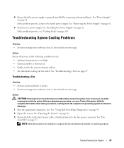
... amber. • Systems management software issues a fan-related error message. See "Using Dell PowerEdge Diagnostics" on page 87. If the problem persists, remove the faulty power supply. NOTE: Wait 30 seconds for complete information about safety precautions, working properly. See "Installing the Power Supply" on page 61. Troubleshooting a Fan Problem • System-status indicator is firmly...
... amber. • Systems management software issues a fan-related error message. See "Using Dell PowerEdge Diagnostics" on page 87. If the problem persists, remove the faulty power supply. NOTE: Wait 30 seconds for complete information about safety precautions, working properly. See "Installing the Power Supply" on page 61. Troubleshooting a Fan Problem • System-status indicator is firmly...
Hardware Owner's Manual (PDF)
Page 99
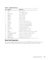
... FAN 13 FP_CONN1 14 IDE 15 HD_ACT 16 INTRUSION_SWITCH 17 I2C HEADER 18 BMC PROG 19 RISER_CONN1 Description Processor socket power supply connector power supply connector Memory module Memory module Memory module Memory module Power connector for the fans Connector for the 3.0 V coin battery Connector for the SATA 0 hard drive Connector for the SATA 1 hard...
... FAN 13 FP_CONN1 14 IDE 15 HD_ACT 16 INTRUSION_SWITCH 17 I2C HEADER 18 BMC PROG 19 RISER_CONN1 Description Processor socket power supply connector power supply connector Memory module Memory module Memory module Memory module Power connector for the fans Connector for the 3.0 V coin battery Connector for the SATA 0 hard drive Connector for the SATA 1 hard...

Hardware Owner's Manual (PDF)
Page 129
... from RAM faster than from the disk drive. AC - A standard interface for the peripheral devices connected to direct configuration and power management. Your system contains an expansion bus that is in a special section of information interpreted by your system by pressing .... security or tracking purposes. ASCII - An individual code assigned to read data from CDs. backup battery - A module that includes power supplies and fans. Baseboard management controller. Otherwise, you start your system. Compact disc. backup - Basic input/output system. Your system's...
... from RAM faster than from the disk drive. AC - A standard interface for the peripheral devices connected to direct configuration and power management. Your system contains an expansion bus that is in a special section of information interpreted by your system by pressing .... security or tracking purposes. ASCII - An individual code assigned to read data from CDs. backup battery - A module that includes power supplies and fans. Baseboard management controller. Otherwise, you start your system. Compact disc. backup - Basic input/output system. Your system's...

Hardware Owner's Manual (PDF)
Page 135
Uninterruptible power supply. A battery-powered unit that automatically supplies power to match the video adapter installed in the system. A USB connector provides a single connection point for example. memory, disk drives, or printers, for multiple.... Windows Server® 2003 - A program used to connect to manage system resources- W - Watt-hour(s). A port on NAS systems. For NAS systems, the Windows Powered operating system is dedicated to Linux, is a way to create common information formats and to display at a specific graphics resolution, you start -up and down...
Uninterruptible power supply. A battery-powered unit that automatically supplies power to match the video adapter installed in the system. A USB connector provides a single connection point for example. memory, disk drives, or printers, for multiple.... Windows Server® 2003 - A program used to connect to manage system resources- W - Watt-hour(s). A port on NAS systems. For NAS systems, the Windows Powered operating system is dedicated to Linux, is a way to create common information formats and to display at a specific graphics resolution, you start -up and down...


