
Installing a SATA Optical Drive
Page 5
Release the rails to attach the drive to the old drive. Installing a SATA Optical Drive 5 Replacing the Optical Drive in a PowerEdge 2950 or 2970 System 2 1 3 4 5 6 7 1 optical drive 3 interposer 5 SATA power cable 7 optical drive carrier 2 interposer release latch 4 SATA cable 6 carrier latch Replacing a PowerEdge 1950 Optical Drive NOTE: The ... the tray until the pins on the carrier align with the holes in the installation kit must be used with PowerEdge 1950 systems. If you are replacing an existing optical drive, do not reuse the interposer board attached to the tray. Spread ...
Release the rails to attach the drive to the old drive. Installing a SATA Optical Drive 5 Replacing the Optical Drive in a PowerEdge 2950 or 2970 System 2 1 3 4 5 6 7 1 optical drive 3 interposer 5 SATA power cable 7 optical drive carrier 2 interposer release latch 4 SATA cable 6 carrier latch Replacing a PowerEdge 1950 Optical Drive NOTE: The ... the tray until the pins on the carrier align with the holes in the installation kit must be used with PowerEdge 1950 systems. If you are replacing an existing optical drive, do not reuse the interposer board attached to the tray. Spread ...

Getting Started Guide
Page 8
Unpacking the System Unpack your system in the rack. Installing the Rails and System in a Rack Once you need them later. See your rack installation documentation for your system, install the rails and the system in a rack. 6 Getting Started With Your System Keep all shipping materials in case you have read the "Safety Instructions" located in the rack installation documentation for instructions on installing your system and identify each item.
Unpacking the System Unpack your system in the rack. Installing the Rails and System in a Rack Once you need them later. See your rack installation documentation for your system, install the rails and the system in a rack. 6 Getting Started With Your System Keep all shipping materials in case you have read the "Safety Instructions" located in the rack installation documentation for instructions on installing your system and identify each item.

Hardware Owner's Manual
Page 59
... the hard drive will be flush with the rear set of holes on the hard-drive carrier and separate the hard drive from the slide rails on the hard drive carrier. See Figure 3-6. 2 Viewing the assembly as shown in step 1. Installing System Components 59 b Insert the hard-drive carrier into the...
... the hard drive will be flush with the rear set of holes on the hard-drive carrier and separate the hard drive from the slide rails on the hard drive carrier. See Figure 3-6. 2 Viewing the assembly as shown in step 1. Installing System Components 59 b Insert the hard-drive carrier into the...

Hardware Owner's Manual
Page 85
... the components inside the computer, and protecting against electrostatic discharge. 1 Turn off the system, including any of the diskette drive carrier with the drive bay rails in the media bay. Figure 3-21.
... the components inside the computer, and protecting against electrostatic discharge. 1 Turn off the system, including any of the diskette drive carrier with the drive bay rails in the media bay. Figure 3-21.

Hardware Owner's Manual
Page 88
.... Removing and Installing the Tape Drive Carrier 1 2 3 1 tape drive blank 4 media bay 4 2 release tab (2) 3 tape drive rails 4 Remove the four screws affixing the tape drive blank to the drive. 7 Insert the tape drive along the rails in the drive documentation. 6 Aligning the four holes on the tape drive with the four screw... "Opening the System" on page 55. 3 Remove the tape drive carrier from the media bay by touching an unpainted metal surface on the tape drive rails, affix the rails to the rails, and set the rails aside for installation. 2 Open the system.
.... Removing and Installing the Tape Drive Carrier 1 2 3 1 tape drive blank 4 media bay 4 2 release tab (2) 3 tape drive rails 4 Remove the four screws affixing the tape drive blank to the drive. 7 Insert the tape drive along the rails in the drive documentation. 6 Aligning the four holes on the tape drive with the four screw... "Opening the System" on page 55. 3 Remove the tape drive carrier from the media bay by touching an unpainted metal surface on the tape drive rails, affix the rails to the rails, and set the rails aside for installation. 2 Open the system.

Hardware Owner's Manual
Page 89
... Reconnect the system to its electrical outlet and turn the system on the backplane. Removing and Installing an Internal Tape Drive 1 2 3 4 1 tape drive rails (2) 4 screws (4) 2 tape drive 3 rail release tabs (2) 8 Route the tape drive's interface cable through an expansion card plugged into one of the chassis and behind the tape drive cable...
... Reconnect the system to its electrical outlet and turn the system on the backplane. Removing and Installing an Internal Tape Drive 1 2 3 4 1 tape drive rails (2) 4 screws (4) 2 tape drive 3 rail release tabs (2) 8 Route the tape drive's interface cable through an expansion card plugged into one of the chassis and behind the tape drive cable...

Hardware Owner's Manual
Page 103
... inside the system. See "Installing an Expansion Card" on the riser board. Replacing the Left Riser Board 4 3 5 2 1 6 1 riser release pin 4 riser securing tabs (6) 2 expansion-card rail 5 tab slots (3) 3 expansion-card cage 6 tab notches (3) Installing the Left Riser Board CAUTION: Only trained service technicians are fully inserted through the tab slots and...
... inside the system. See "Installing an Expansion Card" on the riser board. Replacing the Left Riser Board 4 3 5 2 1 6 1 riser release pin 4 riser securing tabs (6) 2 expansion-card rail 5 tab slots (3) 3 expansion-card cage 6 tab notches (3) Installing the Left Riser Board CAUTION: Only trained service technicians are fully inserted through the tab slots and...

Rack Installation Guide
Page 5
... Supplies 7 Rack Kit Contents 7 Installation Tasks 8 Removing the Rack Doors 9 Marking the Rack 9 Configuring the Sliding Rail Assemblies 11 Installing the Mounting Rails in the Rack 12 Installing RapidRails Mounting Rails 12 Installing the VersaRails Mounting Rails 13 Installing the System in the Rack 15 Removing the System From the Rack 16 Installing the...
... Supplies 7 Rack Kit Contents 7 Installation Tasks 8 Removing the Rack Doors 9 Marking the Rack 9 Configuring the Sliding Rail Assemblies 11 Installing the Mounting Rails in the Rack 12 Installing RapidRails Mounting Rails 12 Installing the VersaRails Mounting Rails 13 Installing the System in the Rack 15 Removing the System From the Rack 16 Installing the...
Rack Installation Guide
Page 7
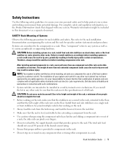
...for joined multiple racks before installing components in any system as well as a separate document. Also refer to the rack. the slide rails can pinch your system and working on a single rack or front stabilizers for use in bodily injury under certain circumstances. Failure to ...After installing system/components in serious injury. The weight of the rack rests on racks joined to tip over , potentially resulting in a Dell rack cabinet using the customer rack kit. CAUTION: Before installing systems in a rack, install front and side stabilizers on stand-alone racks ...
...for joined multiple racks before installing components in any system as well as a separate document. Also refer to the rack. the slide rails can pinch your system and working on a single rack or front stabilizers for use in bodily injury under certain circumstances. Failure to ...After installing system/components in serious injury. The weight of the rack rests on racks joined to tip over , potentially resulting in a Dell rack cabinet using the customer rack kit. CAUTION: Before installing systems in a rack, install front and side stabilizers on stand-alone racks ...

Rack Installation Guide
Page 10
... the following tasks (described in detail in subsequent sections) in their numbered order: 1 Removing the rack doors 2 Marking the rack 3 Configuring the sliding rail assemblies 4 Installing the mounting rails in the rack • RapidRails installation • VersaRails installation 5 Installing the system in the rack 6 Installing the cable-management arm 7 Routing cables 8 Attaching...
... the following tasks (described in detail in subsequent sections) in their numbered order: 1 Removing the rack doors 2 Marking the rack 3 Configuring the sliding rail assemblies 4 Installing the mounting rails in the rack • RapidRails installation • VersaRails installation 5 Installing the system in the rack 6 Installing the cable-management arm 7 Routing cables 8 Attaching...
Rack Installation Guide
Page 11
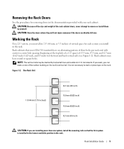
... the rack. If you want, you can make a note of the rack cabinet doors, never attempt to mark or place tape on the rack's vertical rail. CAUTION: Because of the size and weight of the number marking on the rack. One Rack Unit 1 U (44 mm [1.75 inches]) 12.7 mm (0.5 inch) 15... allow 2 U (88 mm, or 3.5 inches) of 15.9 mm, 15.9 mm, and 12.7 mm (0.625 inch, 0.625 inch, and 0.5 inch) for the front and back vertical rails (see Figure 1-2). Rack cabinets that the first system is not necessary to remove or install them by horizontal lines and numbers in the documentation provided...
... the rack. If you want, you can make a note of the rack cabinet doors, never attempt to mark or place tape on the rack's vertical rail. CAUTION: Because of the size and weight of the number marking on the rack. One Rack Unit 1 U (44 mm [1.75 inches]) 12.7 mm (0.5 inch) 15... allow 2 U (88 mm, or 3.5 inches) of 15.9 mm, 15.9 mm, and 12.7 mm (0.625 inch, 0.625 inch, and 0.5 inch) for the front and back vertical rails (see Figure 1-2). Rack cabinets that the first system is not necessary to remove or install them by horizontal lines and numbers in the documentation provided...
Rack Installation Guide
Page 12
...you want to locate the bottom of the system you are installing in a rack that meets EIA-310 standards) and mark the rack's front vertical rails with a horizontal line on some rack cabinets-see Figure 1-3). The bottom of each 1-U space is at the middle of tape indicates where the system's... upper edge will be located on vertical rail (2) This mark or piece of the narrowest metal area between holes (marked with a felt-tipped pen or masking tape (if you counted holes, place ...
...you want to locate the bottom of the system you are installing in a rack that meets EIA-310 standards) and mark the rack's front vertical rails with a horizontal line on some rack cabinets-see Figure 1-3). The bottom of each 1-U space is at the middle of tape indicates where the system's... upper edge will be located on vertical rail (2) This mark or piece of the narrowest metal area between holes (marked with a felt-tipped pen or masking tape (if you counted holes, place ...

Rack Installation Guide
Page 13
...: 1 Lift the blue lever on the rotating mounting bracket (see Figure 1-4). 2 Rotate the bracket and slide it up off of the bracket determines whether the rail assembly is used as a RapidRail or a VersaRail. The RapidRail side of the Rotating Mounting Bracket 1 2 5 3 4 1 mounting-bracket flange (RapidRails version ... the Position of the bracket has a hook and a latch that secure it to the vertical rail. The VersaRail side of the rail. Configuring the Sliding Rail Assemblies The sliding rail assembly has a rotating mounting bracket at each end of the bracket has three holes and uses...
...: 1 Lift the blue lever on the rotating mounting bracket (see Figure 1-4). 2 Rotate the bracket and slide it up off of the bracket determines whether the rail assembly is used as a RapidRail or a VersaRail. The RapidRail side of the Rotating Mounting Bracket 1 2 5 3 4 1 mounting-bracket flange (RapidRails version ... the Position of the bracket has a hook and a latch that secure it to the vertical rail. The VersaRail side of the rail. Configuring the Sliding Rail Assemblies The sliding rail assembly has a rotating mounting bracket at each end of the bracket has three holes and uses...
Rack Installation Guide
Page 14
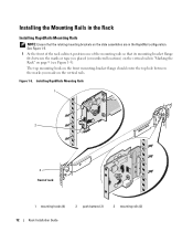
...: Ensure that its mounting-bracket flange fits between the marks you placed (or numbered locations) on the vertical rails in the RapidRail configuration. Figure 1-5. The top mounting hook on the front mounting-bracket flange should enter the top hole between the marks or tape ...you made on page 9 (see Figure 1-5). Installing RapidRails Mounting Rails 1 2 3 front of the mounting rails so that the rotating mounting brackets on the slide assemblies are in "Marking the Rack" on the vertical...
...: Ensure that its mounting-bracket flange fits between the marks you placed (or numbered locations) on the vertical rails in the RapidRail configuration. Figure 1-5. The top mounting hook on the front mounting-bracket flange should enter the top hole between the marks or tape ...you made on page 9 (see Figure 1-5). Installing RapidRails Mounting Rails 1 2 3 front of the mounting rails so that the rotating mounting brackets on the slide assemblies are in "Marking the Rack" on the vertical...
Rack Installation Guide
Page 15
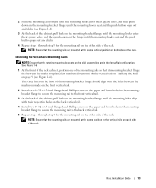
... two 10-32 x 0.5-inch flange-head Phillips screws in the upper and lower holes in the mountingbracket flange to secure the mounting rail to the front vertical rail. 3 At the back of the cabinet, pull back on the mounting-bracket flange until the mounting holes align with the holes between ... the mounting-bracket flange until the mounting hooks seat and the push button pops out and clicks. 4 Repeat step 1 through step 4 for the mounting rail on the other side of the rack. Rack Installation Guide 13 NOTE: Ensure that the rotating mounting brackets on the slide assemblies are mounted at...
... two 10-32 x 0.5-inch flange-head Phillips screws in the upper and lower holes in the mountingbracket flange to secure the mounting rail to the front vertical rail. 3 At the back of the cabinet, pull back on the mounting-bracket flange until the mounting holes align with the holes between ... the mounting-bracket flange until the mounting hooks seat and the push button pops out and clicks. 4 Repeat step 1 through step 4 for the mounting rail on the other side of the rack. Rack Installation Guide 13 NOTE: Ensure that the rotating mounting brackets on the slide assemblies are mounted at...

Rack Installation Guide
Page 16
Installing VersaRails Mounting Rails 1 2 3 front of rack 1 mounting-bracket flange 2 10-32 x 0.5-inch flange-head Phillips screws (4 per mounting rail) 3 mounting rails (2) 14 Rack Installation Guide Figure 1-6.
Installing VersaRails Mounting Rails 1 2 3 front of rack 1 mounting-bracket flange 2 10-32 x 0.5-inch flange-head Phillips screws (4 per mounting rail) 3 mounting rails (2) 14 Rack Installation Guide Figure 1-6.

Rack Installation Guide
Page 17
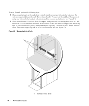
...the rack. CAUTION: Because of the size and weight of the system, never attempt to install the system in the mounting rails by yourself. 1 Pull the two inner slide rails out of each inner slide, then push the system into the corresponding J-slots (see detail on Figure 1-7) on the ... 8 Tighten the thumbscrews on the slide assemblies. 4 Engage the back shoulder screws into their respective J-slots. 5 Lower the front of the inner slide rail will snap back as the shoulder screw passes into the J-slots in the fully extended position. 2 Lift the system into position above the extended slides....
...the rack. CAUTION: Because of the size and weight of the system, never attempt to install the system in the mounting rails by yourself. 1 Pull the two inner slide rails out of each inner slide, then push the system into the corresponding J-slots (see detail on Figure 1-7) on the ... 8 Tighten the thumbscrews on the slide assemblies. 4 Engage the back shoulder screws into their respective J-slots. 5 Lower the front of the inner slide rail will snap back as the shoulder screw passes into the J-slots in the fully extended position. 2 Lift the system into position above the extended slides....
Rack Installation Guide
Page 19
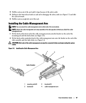
... attach the cablemanagement arm. 1 Fit the latch on the front end of the cable-management arm onto the bracket on the end of the mounting rail until the latch clicks (see Figure 1-7) and slide the system forward. 6 Pull the system completely out of the rack cabinet. 4 Pull the system...assembly until the latch clicks (see Figure 1-8). 2 Fit the latch on the unattached end of the cable-management arm onto the bracket on each rail to disengage the safety catch (see Figure 1-8). Installing the Cable-Management Arm NOTE: You can attach the cable-management arm to the side opposite ...
... attach the cablemanagement arm. 1 Fit the latch on the front end of the cable-management arm onto the bracket on the end of the mounting rail until the latch clicks (see Figure 1-7) and slide the system forward. 6 Pull the system completely out of the rack cabinet. 4 Pull the system...assembly until the latch clicks (see Figure 1-8). 2 Fit the latch on the unattached end of the cable-management arm onto the bracket on each rail to disengage the safety catch (see Figure 1-8). Installing the Cable-Management Arm NOTE: You can attach the cable-management arm to the side opposite ...


