AMD Processor Update
Page 1
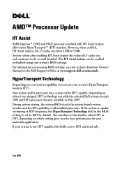
... not HT3 capable, this field is set to HT3 by default. HyperTransport Technology Depending on the Dell Support website at HT3 frequency, the HyperTransport Technology field in the BIOS settings is capable of all installed processors. However, when enabled, HT Assist reduces the L3 cache size from 6 MB to HT3. If the...
... not HT3 capable, this field is set to HT3 by default. HyperTransport Technology Depending on the Dell Support website at HT3 frequency, the HyperTransport Technology field in the BIOS settings is capable of all installed processors. However, when enabled, HT Assist reduces the L3 cache size from 6 MB to HT3. If the...
Information Update
Page 6
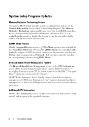
... for the Embedded SATA field. SUSE Linux Enterprise Server 9 supports demand-based power management on dual-core AMD processors, but not on the newer quad-core processors. The Memory Optimizer Technology option enables you to set to run the controllers in the default 128-bit mode...ECC. SUSE® Linux Enterprise Server 10 fully supports demand-based power management. Additional CPU Information On the CPU Information screen, the processor fields now indicate the family, model, and stepping of the System Setup Program. System Setup Program Updates Memory Optimizer Technology Feature The ...
... for the Embedded SATA field. SUSE Linux Enterprise Server 9 supports demand-based power management on dual-core AMD processors, but not on the newer quad-core processors. The Memory Optimizer Technology option enables you to set to run the controllers in the default 128-bit mode...ECC. SUSE® Linux Enterprise Server 10 fully supports demand-based power management. Additional CPU Information On the CPU Information screen, the processor fields now indicate the family, model, and stepping of the System Setup Program. System Setup Program Updates Memory Optimizer Technology Feature The ...
Information Update
Page 12
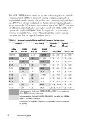
... by DIMM ranks, one-fourth of a quad-rank DIMM (one -half of a dual-rank DIMM or the full capacity of a single-rank DIMM. and Dual-Processor Configurations Processor 1 Processor 2 Available Memory Spared Memory DIMM Pair 1/2 DIMM Pair 3/4 DIMM Pair 5/6 DIMM Pair 7/8 1 CPU / 2 CPUs 1 CPU / 2 CPUs 512 MB 512 MB 512 MB 512 MB...
... by DIMM ranks, one-fourth of a quad-rank DIMM (one -half of a dual-rank DIMM or the full capacity of a single-rank DIMM. and Dual-Processor Configurations Processor 1 Processor 2 Available Memory Spared Memory DIMM Pair 1/2 DIMM Pair 3/4 DIMM Pair 5/6 DIMM Pair 7/8 1 CPU / 2 CPUs 1 CPU / 2 CPUs 512 MB 512 MB 512 MB 512 MB...
Getting Started Guide
Page 5
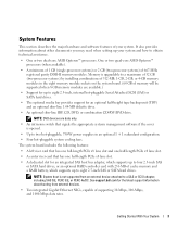
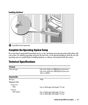
...slot. • A dedicated slot for up your system. Getting Started With Your System 3 Memory is upgradable to a maximum of 32 GB (two-processor systems) by installing combinations of 512-MB, 1-GB, 2-GB, or 4-GB memory modules in an optional 1 + 1 redundant configuration. • ...two dual-core AMD Opteron™ processors. One or two quad-core AMD Opteron™ processors (when available). • A minimum of 1 GB (single-processor systems) or 2 GB (two-processor systems) of 667-MHz registered parity DDR-II memory modules. See support.dell.com for an optional half-height tape...
...slot. • A dedicated slot for up your system. Getting Started With Your System 3 Memory is upgradable to a maximum of 32 GB (two-processor systems) by installing combinations of 512-MB, 1-GB, 2-GB, or 4-GB memory modules in an optional 1 + 1 redundant configuration. • ...two dual-core AMD Opteron™ processors. One or two quad-core AMD Opteron™ processors (when available). • A minimum of 1 GB (single-processor systems) or 2 GB (two-processor systems) of 667-MHz registered parity DDR-II memory modules. See support.dell.com for an optional half-height tape...
Getting Started Guide
Page 11
... Expansion Bus Bus type Expansion slots Center riser: PCIe Left riser PCIe option: One or two dual-core AMD Opteron processors One or two quad-core AMD Opteron processors (when available) PCIe One x8 full-height, half-length 3.3-V slot One x8 full-height, full-length 3.3-V slot One x4 full-height, half-length...
... Expansion Bus Bus type Expansion slots Center riser: PCIe Left riser PCIe option: One or two dual-core AMD Opteron processors One or two quad-core AMD Opteron processors (when available) PCIe One x8 full-height, half-length 3.3-V slot One x8 full-height, full-length 3.3-V slot One x4 full-height, half-length...

Getting Started Guide
Page 12
... memory modules Eight 240-pin 512 MB, 1 GB, 2 GB, or 4 GB (8 GB when available) 1 GB (one processor) or 2 GB (two processors) 16 GB (one processor) or 32 GB (two processors) (32 GB (one processor) or 64 GB (two processors) when 8 GB memory modules are available) Up to eight 2.5-inch, hot-plug SAS or SATA internal drives...
... memory modules Eight 240-pin 512 MB, 1 GB, 2 GB, or 4 GB (8 GB when available) 1 GB (one processor) or 2 GB (two processors) 16 GB (one processor) or 32 GB (two processors) (32 GB (one processor) or 64 GB (two processors) when 8 GB memory modules are available) Up to eight 2.5-inch, hot-plug SAS or SATA internal drives...

Hardware Owner's Manual
Page 6
... 91 General Memory Module Installation Guidelines 91 Memory Sparing Support 92 Installing Memory Modules 94 Removing Memory Modules 95 Integrated NIC TOE 96 Processors 96 Removing a Processor 96 Installing a Processor 98 System Battery 100 Replacing the System Battery 100 Expansion-Card Riser Boards 102 Removing the Left Expansion-Card Riser Board 102 Installing...
... 91 General Memory Module Installation Guidelines 91 Memory Sparing Support 92 Installing Memory Modules 94 Removing Memory Modules 95 Integrated NIC TOE 96 Processors 96 Removing a Processor 96 Installing a Processor 98 System Battery 100 Replacing the System Battery 100 Expansion-Card Riser Boards 102 Removing the Left Expansion-Card Riser Board 102 Installing...

Hardware Owner's Manual
Page 21
...page 147. 2.5V PwrGd 2.5V voltage regulator has failed. PCI riser has failed. CPU # VCORE Processor # VCORE voltage regulator has failed. exceeded the allowable voltage range CPU # VDDA Processor # VDDA voltage has exceeded the allowable voltage range See "Getting Help" on page 123. has failed...on page 147. See "Getting Help" on page 123. For component failures, see "Getting Help" on page 147. CPU VTT PwrGd Processor # VTT voltage has exceeded the allowable voltage range See "Getting Help" on page 147. Specified voltage regulator has See "Getting Help" on...
...page 147. 2.5V PwrGd 2.5V voltage regulator has failed. PCI riser has failed. CPU # VCORE Processor # VCORE voltage regulator has failed. exceeded the allowable voltage range CPU # VDDA Processor # VDDA voltage has exceeded the allowable voltage range See "Getting Help" on page 123. has failed...on page 147. See "Getting Help" on page 123. For component failures, see "Getting Help" on page 147. CPU VTT PwrGd Processor # VTT voltage has exceeded the allowable voltage range See "Getting Help" on page 147. Specified voltage regulator has See "Getting Help" on...

Hardware Owner's Manual
Page 22
.... Specified microprocessor is out of over- Specified processor is missing or See "Troubleshooting the bad, and the system is possibly, but not always, caused by Dell. Cooling Problems" on page 133. Another fan failure additional scrolling messages. Processor # has had an internal error (IERR)... that is in an Microprocessors" on page 123. processor protocol error. 22 About Your System See the Dell OpenManage Baseboard Management Controller User's Guide for redundant. The system BIOS has reported a See "Getting Help" on...
.... Specified microprocessor is out of over- Specified processor is missing or See "Troubleshooting the bad, and the system is possibly, but not always, caused by Dell. Cooling Problems" on page 133. Another fan failure additional scrolling messages. Processor # has had an internal error (IERR)... that is in an Microprocessors" on page 123. processor protocol error. 22 About Your System See the Dell OpenManage Baseboard Management Controller User's Guide for redundant. The system BIOS has reported a See "Getting Help" on...
Hardware Owner's Manual
Page 23
... power supply. PS # Input Range Power source for specified power supply is unavailable, or out of acceptable range. If the last Supplies" on page 122. processor initialization error. If the problem persists, see "Troubleshooting Power Supplies" on page 122. PS AC Current Power source is improperly installed or faulty. Table 1-6. PS...
... power supply. PS # Input Range Power source for specified power supply is unavailable, or out of acceptable range. If the last Supplies" on page 122. processor initialization error. If the problem persists, see "Troubleshooting Power Supplies" on page 122. PS AC Current Power source is improperly installed or faulty. Table 1-6. PS...
Hardware Owner's Manual
Page 29
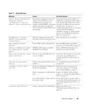
... information, see "Troubleshooting System Memory" on system CMOS has been cleared. Please wait... Remote BIOS update attempt failed. Microprocessors with different cache sizes detected! See "Processors" on page 126. About Your System 29 Replace the diskette. Table 1-7. If the problem persists, see "General functionality. correct the settings. If the problem drive...
... information, see "Troubleshooting System Memory" on system CMOS has been cleared. Please wait... Remote BIOS update attempt failed. Microprocessors with different cache sizes detected! See "Processors" on page 126. About Your System 29 Replace the diskette. Table 1-7. If the problem persists, see "General functionality. correct the settings. If the problem drive...
Hardware Owner's Manual
Page 34
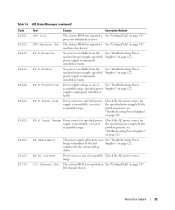
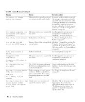
...See the CDs that was pressed during the error. Check both DIMMs for information that came with your system. See "Installing a Processor" on the boot hard drive. Time-of -day not set please run SETUP program Incorrect Time or Date settings; Unsupported CPU ...are disabled: DIMM n1 n2 Total memory size is informative and can be faulty. Timer chip counter 2 failed Faulty system board. See "Processors" on page 122. See "Troubleshooting the System Battery" on page 96. Table 1-7. System Messages (continued) Message Causes Corrective Actions The amount...
...See the CDs that was pressed during the error. Check both DIMMs for information that came with your system. See "Installing a Processor" on the boot hard drive. Time-of -day not set please run SETUP program Incorrect Time or Date settings; Unsupported CPU ...are disabled: DIMM n1 n2 Total memory size is informative and can be faulty. Timer chip counter 2 failed Faulty system board. See "Processors" on page 122. See "Troubleshooting the System Battery" on page 96. Table 1-7. System Messages (continued) Message Causes Corrective Actions The amount...
Hardware Owner's Manual
Page 35
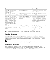
..., a message will run system diagnostics, an error message may lose all data on CPUn module(s) used in this table, see the documentation that section for processor n Micro code update failed. For more Faulty or improperly seated memory See "Troubleshooting System Memory" faulty DIMMs found on the diskette. No micro code update...
..., a message will run system diagnostics, an error message may lose all data on CPUn module(s) used in this table, see the documentation that section for processor n Micro code update failed. For more Faulty or improperly seated memory See "Troubleshooting System Memory" faulty DIMMs found on the diskette. No micro code update...
Hardware Owner's Manual
Page 41
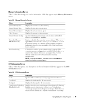
...Node Interleaving field must be used by software that appear on page 92. Virtualization Technology (Disabled default) Displays when the processor(s) support Virtualization Technology. Memory Information Screen Option System Memory Size System Memory Type System Memory Speed Video Memory System Memory ...Table 2-3 lists the descriptions for the information fields that appear on the CPU Information screen. Displays the type of the processor(s). Enables or disables the redundant memory feature. Bus Speed Displays the bus speed of system memory. Enabled permits virtualization software ...
...Node Interleaving field must be used by software that appear on page 92. Virtualization Technology (Disabled default) Displays when the processor(s) support Virtualization Technology. Memory Information Screen Option System Memory Size System Memory Type System Memory Speed Video Memory System Memory ...Table 2-3 lists the descriptions for the information fields that appear on the CPU Information screen. Displays the type of the processor(s). Enables or disables the redundant memory feature. Bus Speed Displays the bus speed of system memory. Enabled permits virtualization software ...
Hardware Owner's Manual
Page 42
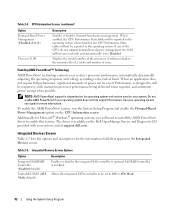
...Devices Screen Table 2-5 lists the options and descriptions for the information fields that appear on the Dell OpenManage Service and Diagnostic CD provided with maximum processor performance being delivered when required, and automatic power savings when possible. technology controls your system.... controller or optional SAS RAID controller, if installed. CPU Information Screen (continued) Option Demand-Based Power Management (Disabled default) Processor X ID Description Enables or disables demand-based power management. Displays the model number of cores. support is available on the ...
...Devices Screen Table 2-5 lists the options and descriptions for the information fields that appear on the Dell OpenManage Service and Diagnostic CD provided with maximum processor performance being delivered when required, and automatic power savings when possible. technology controls your system.... controller or optional SAS RAID controller, if installed. CPU Information Screen (continued) Option Demand-Based Power Management (Disabled default) Processor X ID Description Enables or disables demand-based power management. Displays the model number of cores. support is available on the ...
Hardware Owner's Manual
Page 51
...; Expansion cards • Expansion card cage • Cooling shroud • Fan bracket • RAC card • Optical, diskette, and tape drives • System memory • Processors • System battery • Expansion-card riser boards • Sideplane board • SAS/SATA Backplane board • Control panel assembly • System board Recommended Tools...
...; Expansion cards • Expansion card cage • Cooling shroud • Fan bracket • RAC card • Optical, diskette, and tape drives • System memory • Processors • System battery • Expansion-card riser boards • Sideplane board • SAS/SATA Backplane board • Control panel assembly • System board Recommended Tools...

Hardware Owner's Manual
Page 74
... cards from the left expansion-card riser board. 5 Remove the left riser board. See Figure 3-14. NOTE: You must install a filler bracket over the system processor(s) and memory modules. NOTICE: Never operate your Product Information Guide for some time after the system has been powered down. b Grasp the expansion card by...
... cards from the left expansion-card riser board. 5 Remove the left riser board. See Figure 3-14. NOTE: You must install a filler bracket over the system processor(s) and memory modules. NOTICE: Never operate your Product Information Guide for some time after the system has been powered down. b Grasp the expansion card by...

Hardware Owner's Manual
Page 75
... the pivots located on each end of the cooling shroud. 5 Reinstall the left riser board. See Figure 3-15. 2 Lower the shroud straight down over the processor(s) and memory modules. 4 Route the optical drive cable through the cable tabs on the pivots. 3 Rotate the shroud down into the system until the hinges...
... the pivots located on each end of the cooling shroud. 5 Reinstall the left riser board. See Figure 3-15. 2 Lower the shroud straight down over the processor(s) and memory modules. 4 Route the optical drive cable through the cable tabs on the pivots. 3 Rotate the shroud down into the system until the hinges...
Hardware Owner's Manual
Page 91
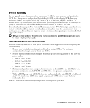
...Node Interleaving option. DIMM 3 and DIMM 4 - Table 3-1 shows the available memory configurations following these guidelines. Each processor has its respective processor. General Memory Module Installation Guidelines To ensure optimal performance of your system, observe the following guidelines when configuring your ... with a pair of DIMMs of a different size (N+3, or up to its own memory controller and local memory for a two-processor configuration) by installing 667-MHz registered parity DDR-II memory modules (DIMMs) in the following pairs of sockets: - Installing System...
...Node Interleaving option. DIMM 3 and DIMM 4 - Table 3-1 shows the available memory configurations following these guidelines. Each processor has its respective processor. General Memory Module Installation Guidelines To ensure optimal performance of your system, observe the following guidelines when configuring your ... with a pair of DIMMs of a different size (N+3, or up to its own memory controller and local memory for a two-processor configuration) by installing 667-MHz registered parity DDR-II memory modules (DIMMs) in the following pairs of sockets: - Installing System...
Hardware Owner's Manual
Page 92
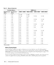
...Setup program. See "Using the System Setup Program" on opposite sides of the fully populated memory configurations shown in single- or dual-processor systems that have one of the processor sockets. Memory sparing is supported in Table 3-1. DIMM Socket DIMM 1 / DIMM 5 DIMM 2/ DIMM 6 DIMM 3/ DIMM 7... independently to the two groups of DIMMs on page 37. To use memory sparing, you must disable node interleaving. Memory Configurations Total System Memory Single-Processor Dual-Processor System System 1 GB 2 GB 2 GB 4 GB 2 GB 4 GB 3 GB 6 GB 4 GB 8 GB 4 GB 8 GB 5 GB 10 ...
...Setup program. See "Using the System Setup Program" on opposite sides of the fully populated memory configurations shown in single- or dual-processor systems that have one of the processor sockets. Memory sparing is supported in Table 3-1. DIMM Socket DIMM 1 / DIMM 5 DIMM 2/ DIMM 6 DIMM 3/ DIMM 7... independently to the two groups of DIMMs on page 37. To use memory sparing, you must disable node interleaving. Memory Configurations Total System Memory Single-Processor Dual-Processor System System 1 GB 2 GB 2 GB 4 GB 2 GB 4 GB 3 GB 6 GB 4 GB 8 GB 4 GB 8 GB 5 GB 10 ...


