AMD Processor Update
Page 1
... field in May 2009. During system startup, the system BIOS checks the system board revision number and the HT capability of running at www.support.dell.com/manuals. July 2009 However, when enabled, HT Assist reduces the L3 cache size from 6 MB to do so until disabled. System reboot after enabling ... in early 2009 and HT3 processors became available in the BIOS settings is set your system's BIOS settings. If your system's Hardware Owner's Manual on when it was added to HT1 and read only. For information on accessing BIOS settings, see your system is not HT3 capable, this ...
... field in May 2009. During system startup, the system BIOS checks the system board revision number and the HT capability of running at www.support.dell.com/manuals. July 2009 However, when enabled, HT Assist reduces the L3 cache size from 6 MB to do so until disabled. System reboot after enabling ... in early 2009 and HT3 processors became available in the BIOS settings is set your system's BIOS settings. If your system's Hardware Owner's Manual on when it was added to HT1 and read only. For information on accessing BIOS settings, see your system is not HT3 capable, this ...

Installing a SATA Optical Drive
Page 3
... a SATA Optical Drive These instructions apply to Dell™ PowerEdge™ systems to remove the system cover and access any of the components inside the system. See "Removing the Bezel" in your Hardware Owner's Manual for specific step instructions. See "Removing a SAS... Controller Daughter Card" in your Hardware Owner's Manual. 4 PowerEdge 1950 systems only: Disconnect and remove the SAS controller daughter card. c Release...
... a SATA Optical Drive These instructions apply to Dell™ PowerEdge™ systems to remove the system cover and access any of the components inside the system. See "Removing the Bezel" in your Hardware Owner's Manual for specific step instructions. See "Removing a SAS... Controller Daughter Card" in your Hardware Owner's Manual. 4 PowerEdge 1950 systems only: Disconnect and remove the SAS controller daughter card. c Release...

Installing a SATA Optical Drive
Page 7
Figure 1-3. See "Closing the System" in your Hardware Owner's Manual. 6 Close the system. Installing the SATA Optical Drive - PowerEdge 2970 or 2950 1 Insert the optical drive tray into the system until it is fully inserted and locked into position. 2 Connect... 5 Reinstall the SAS controller daughter card and reconnect the SAS cable. SATA Cable Routing in your Hardware Owner's Manual. 7 Reconnect the system to the power supply connector. See "SAS Controller Daughter Card" in the PowerEdge 1950 2 1 3 4 6 5 1 SATA data cable 3 chipset shroud 5 SATA power cable 2 SATA_A ...
Figure 1-3. See "Closing the System" in your Hardware Owner's Manual. 6 Close the system. Installing the SATA Optical Drive - PowerEdge 2970 or 2950 1 Insert the optical drive tray into the system until it is fully inserted and locked into position. 2 Connect... 5 Reinstall the SAS controller daughter card and reconnect the SAS cable. SATA Cable Routing in your Hardware Owner's Manual. 7 Reconnect the system to the power supply connector. See "SAS Controller Daughter Card" in the PowerEdge 1950 2 1 3 4 6 5 1 SATA data cable 3 chipset shroud 5 SATA power cable 2 SATA_A ...

Installing a SATA Optical Drive
Page 8
... 2 cable retention bracket 3 SATA data cable 4 SATA power cable 5 optical drive 8 Installing a SATA Optical Drive Figure 1-4. See "Removing the Cooling Shroud" in your Hardware Owner's Manual. 5 Remove the cable retention bracket from the right interior wall of the chassis by pushing the blue release latch and sliding the bracket toward the... front of the system until the bracket detaches from the chassis slots. 6 Route the SATA cable in the cable channel in the PowerEdge 2950 and 2970 1 2 3 4 5 1 SATA_B connector on the system board. 4 Remove the cooling shroud.
... 2 cable retention bracket 3 SATA data cable 4 SATA power cable 5 optical drive 8 Installing a SATA Optical Drive Figure 1-4. See "Removing the Cooling Shroud" in your Hardware Owner's Manual. 5 Remove the cable retention bracket from the right interior wall of the chassis by pushing the blue release latch and sliding the bracket toward the... front of the system until the bracket detaches from the chassis slots. 6 Route the SATA cable in the cable channel in the PowerEdge 2950 and 2970 1 2 3 4 5 1 SATA_B connector on the system board. 4 Remove the cooling shroud.

Installing a SATA Optical Drive
Page 9
... of the optical drive. 4 Use the appropriate power cable provided in your Hardware Owner's Manual. 10 Close the system. For a PowerEdge 1900, use the SATA_B connector. - See Figure 1-5. - Installing a SATA Optical Drive 9 For a PowerEdge 2900, use the SATA_D connector. For a PowerEdge 2900 system, connect to an available power supply cable. 5 Replace the center fan...
... of the optical drive. 4 Use the appropriate power cable provided in your Hardware Owner's Manual. 10 Close the system. For a PowerEdge 1900, use the SATA_B connector. - See Figure 1-5. - Installing a SATA Optical Drive 9 For a PowerEdge 2900, use the SATA_D connector. For a PowerEdge 2900 system, connect to an available power supply cable. 5 Replace the center fan...

Installing a SATA Optical Drive
Page 10
See "Closing the System" in a PowerEdge 2900 or 1900 3 2 4 5 1 1 optical drive 3 SATA data cable 5 SATA power connector on SAS backplane (PowerEdge 2900 only) 2 SATA power cable 4 SATA connector on the system and attached peripherals. 10 Installing a SATA Optical Drive Figure 1-5. SATA Cable Routing in your Hardware Owner's Manual. 10 Reconnect the system to power and turn on system board 8 Reconnect the cables to the SAS controller daughter card. 9 Close the system.
See "Closing the System" in a PowerEdge 2900 or 1900 3 2 4 5 1 1 optical drive 3 SATA data cable 5 SATA power connector on SAS backplane (PowerEdge 2900 only) 2 SATA power cable 4 SATA connector on the system and attached peripherals. 10 Installing a SATA Optical Drive Figure 1-5. SATA Cable Routing in your Hardware Owner's Manual. 10 Reconnect the system to power and turn on system board 8 Reconnect the cables to the SAS controller daughter card. 9 Close the system.
Information Update
Page 3
Contents Non-Optimal Memory Configurations 5 Regional Hardware Owner's Manuals Available on the Web 5 Using the Online Diagnostics 5 System Setup Program Updates 6 Memory Optimizer Technology Feature 6 QDMA Mode Feature 6 Demand-Based Power Management Feature . . . . 6 Additional CPU Information 6 Default Settings Update 7 System Start-up Behavior 7 Overcurrent Events on USB Ports 7 LCD Status Message Update 8 System Board Jumpers 9 Creating a BMC User Password 10 System Memory Update 11 Contents 3
Contents Non-Optimal Memory Configurations 5 Regional Hardware Owner's Manuals Available on the Web 5 Using the Online Diagnostics 5 System Setup Program Updates 6 Memory Optimizer Technology Feature 6 QDMA Mode Feature 6 Demand-Based Power Management Feature . . . . 6 Additional CPU Information 6 Default Settings Update 7 System Start-up Behavior 7 Overcurrent Events on USB Ports 7 LCD Status Message Update 8 System Board Jumpers 9 Creating a BMC User Password 10 System Memory Update 11 Contents 3
Information Update
Page 5
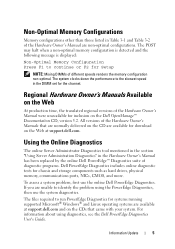
...: Mixing DIMMs of the Hardware Owner's Manuals that came with your system. To assess a system problem, first use the system diagnostics. For information about using the PowerEdge Diagnostics, then use the online Dell PowerEdge Diagnostics. All versions of different speeds renders... Diagnostics" in the Hardware Owner's Manual has been replaced by the online Dell PowerEdge™ Diagnostics suite of the Hardware Owner's Manual are unable to the slowest speed in Table 3-1 and Table 3-2 of diagnostic programs. Dell PowerEdge Diagnostics includes online diagnostic tests for ...
...: Mixing DIMMs of the Hardware Owner's Manuals that came with your system. To assess a system problem, first use the system diagnostics. For information about using the PowerEdge Diagnostics, then use the online Dell PowerEdge Diagnostics. All versions of different speeds renders... Diagnostics" in the Hardware Owner's Manual has been replaced by the online Dell PowerEdge™ Diagnostics suite of the Hardware Owner's Manual are unable to the slowest speed in Table 3-1 and Table 3-2 of diagnostic programs. Dell PowerEdge Diagnostics includes online diagnostic tests for ...
Information Update
Page 7
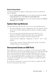
..., the system may display the following events that may need to remove or replace the USB device(s) connected to information listed in your Hardware Owner's Manual. • On the Serial Communication screen, the default setting for the Serial Communication field is On without Console Redirection. • On the Serial Communication screen...
..., the system may display the following events that may need to remove or replace the USB device(s) connected to information listed in your Hardware Owner's Manual. • On the Serial Communication screen, the default setting for the Serial Communication field is On without Console Redirection. • On the Serial Communication screen...

Information Update
Page 8
... CPU Change the CPUs to a matched Mismatch pairing in the system event log (SEL). Table 1-1. If the power supply has failed, see your Hardware Owner's Manual. not supported. 8 Information Update LCD Status Messages Code E1232 E141C Text Causes Corrective Actions VDD 12V AC power was lost on PS# PwrGd the specified...
... CPU Change the CPUs to a matched Mismatch pairing in the system event log (SEL). Table 1-1. If the power supply has failed, see your Hardware Owner's Manual. not supported. 8 Information Update LCD Status Messages Code E1232 E141C Text Causes Corrective Actions VDD 12V AC power was lost on PS# PwrGd the specified...

Information Update
Page 9
System Board Jumpers Information Update 9 The correct settings are incorrect. System Board Jumpers The jumper settings shown in Figure 6-1 and described in Table 6-1 of your system's Hardware Owner's Manual are shown in Figure 1-1 and described in Table 1-2. Figure 1-1.
System Board Jumpers Information Update 9 The correct settings are incorrect. System Board Jumpers The jumper settings shown in Figure 6-1 and described in Table 6-1 of your system's Hardware Owner's Manual are shown in Figure 1-1 and described in Table 1-2. Figure 1-1.
Information Update
Page 11
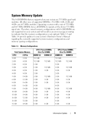
... supported on your system are 533-MHz quad-rank modules. Table 1-3 and Table 1-4 provide updates to indicate that are supported on your system's Hardware Owner's Manual regarding the currently supported system memory configurations and memory sparing configurations. Therefore, mixed memory configurations with a mix of supported DIMMs-512-MB, 1-GB, 2-GB, and...
... supported on your system are 533-MHz quad-rank modules. Table 1-3 and Table 1-4 provide updates to indicate that are supported on your system's Hardware Owner's Manual regarding the currently supported system memory configurations and memory sparing configurations. Therefore, mixed memory configurations with a mix of supported DIMMs-512-MB, 1-GB, 2-GB, and...
Information Update
Page 12
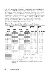
... are quad-rank modules. Memory Sparing in a similar configuration. Indicates a spared dual-rank DIMM (2-GB or 4-GB). Using quad-rank DIMMs in your Hardware Owner's Manual regarding memory sparing configurations that are supported on your system are supported on your system. Table 1-4 supersedes the information provided in a memory sparing configuration provides...
... are quad-rank modules. Memory Sparing in a similar configuration. Indicates a spared dual-rank DIMM (2-GB or 4-GB). Using quad-rank DIMMs in your Hardware Owner's Manual regarding memory sparing configurations that are supported on your system are supported on your system. Table 1-4 supersedes the information provided in a memory sparing configuration provides...
Information Update
Page 15
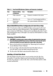
See "Removing the Front Bezel" in your Hardware Owner's Manual. 2 Insert your finger under the shrouded end of the blank and press in on the other end of the blank outward until it , you remove a ...
See "Removing the Front Bezel" in your Hardware Owner's Manual. 2 Insert your finger under the shrouded end of the blank and press in on the other end of the blank outward until it , you remove a ...
Information Update
Page 16
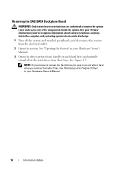
... which bay. See your Product Information Guide for complete information about safety precautions, working inside the system. See "Opening the System" in your Hardware Owner's Manual. 3 Open the drive-carrier release handle on each hard drive and partially extend all of the components inside the computer, and protecting against electrostatic discharge... off the system and attached peripherals, and disconnect the system from their bays. See Figure 1-3. See "Removing a Hot-Plug Hard Drive" in your Hardware Owner's Manual. 16 Information Update
... which bay. See your Product Information Guide for complete information about safety precautions, working inside the system. See "Opening the System" in your Hardware Owner's Manual. 3 Open the drive-carrier release handle on each hard drive and partially extend all of the components inside the computer, and protecting against electrostatic discharge... off the system and attached peripherals, and disconnect the system from their bays. See Figure 1-3. See "Removing a Hot-Plug Hard Drive" in your Hardware Owner's Manual. 16 Information Update
Information Update
Page 17
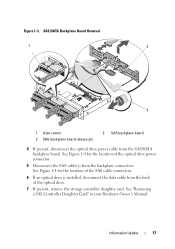
... location of the optical drive power connector. 5 Disconnect the SAS cable(s) from the backplane connectors. See "Removing a SAS Controller Daughter Card" in your Hardware Owner's Manual. Information Update 17 See Figure 1-4 for the location of the optical drive. 7 If present, remove the storage controller daughter card. Figure 1-3. SAS/SATA Backplane Board...
... location of the optical drive power connector. 5 Disconnect the SAS cable(s) from the backplane connectors. See "Removing a SAS Controller Daughter Card" in your Hardware Owner's Manual. Information Update 17 See Figure 1-4 for the location of the optical drive. 7 If present, remove the storage controller daughter card. Figure 1-3. SAS/SATA Backplane Board...
Information Update
Page 18
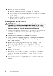
...to the backplane board. See Figure 1-3. 2 Pull the SAS-backplane board release pin. See "Installing the Optical Drive" in your Hardware Owner's Manual. 8 Close the system. 8 Remove the SAS backplane board: a Pull the SAS-backplane board release pin. See Figure 1-3. 3 While pulling ... Board WARNING: Only trained service technicians are fully inserted into place. 4 Reinstall the SAS controller daughter card. See your Hardware Owner's Manual. 5 Reattach the SAS controller daughter card cables and the control panel cable. 6 Reinsert the hard drives. 7 If applicable, reconnect the...
...to the backplane board. See Figure 1-3. 2 Pull the SAS-backplane board release pin. See "Installing the Optical Drive" in your Hardware Owner's Manual. 8 Close the system. 8 Remove the SAS backplane board: a Pull the SAS-backplane board release pin. See Figure 1-3. 3 While pulling ... Board WARNING: Only trained service technicians are fully inserted into place. 4 Reinstall the SAS controller daughter card. See your Hardware Owner's Manual. 5 Reattach the SAS controller daughter card cables and the control panel cable. 6 Reinsert the hard drives. 7 If applicable, reconnect the...

Getting Started Guide
Page 7
...performing the following procedure, read the updates first because they often supersede information in all locations. Getting Started With Your System 5 Dell™ Enterprise Training and Certification is available; see your Product Information Guide. This section describes the steps to set up your ...system into a rack. • The Hardware Owner's Manual provides information about system features and describes how to troubleshoot the system and install or replace system components. • CDs included ...
...performing the following procedure, read the updates first because they often supersede information in all locations. Getting Started With Your System 5 Dell™ Enterprise Training and Certification is available; see your Product Information Guide. This section describes the steps to set up your ...system into a rack. • The Hardware Owner's Manual provides information about system features and describes how to troubleshoot the system and install or replace system components. • CDs included ...

Rack Installation Guide
Page 20
... into place. 3 Attach the I/O cable connectors and power cable connectors to its connector on cable connections, see your system's Getting Started Guide or Hardware Owner's Manual.
... into place. 3 Attach the I/O cable connectors and power cable connectors to its connector on cable connections, see your system's Getting Started Guide or Hardware Owner's Manual.

