
Installing a SATA Optical Drive
Page 6
... SATA cable (the end with a cable provided in the optical drive kit. 4 Route the SATA cable to the power supply connector. a Route the cable through the power cable cutout in a PowerEdge 1950 Drive Tray 2 3 1 4 5 1 optical drive 3 SATA power cable 5 optical drive carrier 2 SATA cable 4 carrier latch Installing the SATA Optical Drive - See Figure 1-3. Figure 1-2. c Connect...
... SATA cable (the end with a cable provided in the optical drive kit. 4 Route the SATA cable to the power supply connector. a Route the cable through the power cable cutout in a PowerEdge 1950 Drive Tray 2 3 1 4 5 1 optical drive 3 SATA power cable 5 optical drive carrier 2 SATA cable 4 carrier latch Installing the SATA Optical Drive - See Figure 1-3. Figure 1-2. c Connect...

Installing a SATA Optical Drive
Page 7
... the system. See "Closing the System" in the PowerEdge 1950 2 1 3 4 6 5 1 SATA data cable 3 chipset shroud 5 SATA power cable 2 SATA_A connector on the system and attached peripherals. Figure 1-3. Installing the SATA Optical Drive - Installing a SATA Optical Drive 7 See "SAS Controller Daughter Card" in your Hardware Owner's Manual. 7 Reconnect the system to the power supply connector.
... the system. See "Closing the System" in the PowerEdge 1950 2 1 3 4 6 5 1 SATA data cable 3 chipset shroud 5 SATA power cable 2 SATA_A connector on the system and attached peripherals. Figure 1-3. Installing the SATA Optical Drive - Installing a SATA Optical Drive 7 See "SAS Controller Daughter Card" in your Hardware Owner's Manual. 7 Reconnect the system to the power supply connector.

Installing a SATA Optical Drive
Page 9
.... See "Closing the System" in your Hardware Owner's Manual. 11 Reconnect the system to the power supply as follows: - For a PowerEdge 1900 system, connect to the system board over the top of the optical drive. 4 Use the appropriate power cable provided in your Hardware Owner's Manual. 10 Close the system. See Figure 1-5. - See "Replacing...
.... See "Closing the System" in your Hardware Owner's Manual. 11 Reconnect the system to the power supply as follows: - For a PowerEdge 1900 system, connect to the system board over the top of the optical drive. 4 Use the appropriate power cable provided in your Hardware Owner's Manual. 10 Close the system. See Figure 1-5. - See "Replacing...

Information Update
Page 8
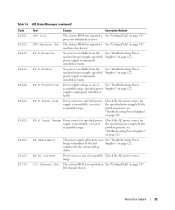
.... LCD Status Messages Code E1232 E141C Text Causes Corrective Actions VDD 12V AC power was lost on PS# PwrGd the specified power supply while the system was not lost , this message is pair or other valid configuration. If AC power was powered on the SEL and configuring systems management settings, see "Getting Help" in your...
.... LCD Status Messages Code E1232 E141C Text Causes Corrective Actions VDD 12V AC power was lost on PS# PwrGd the specified power supply while the system was not lost , this message is pair or other valid configuration. If AC power was powered on the SEL and configuring systems management settings, see "Getting Help" in your...
Information Update
Page 13
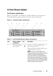
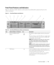
...Indicators, Buttons, and Connectors Item Indicator, Button, Icon Description or Connector 1 Power-on indicator, power button The power-on indicator lights when the system power is turned off immediately after the power button is pressed. Information Update 13 3.5-Inch Chassis Update Front Features and ... running an ACPI-compliant operating system, the system performs a graceful shutdown before the power is on the system's front panel. Front-Panel Features and Indicators 1 2 34 5 6 7 8 Table 1-5. The power button controls the DC power supply output to the system.
...Indicators, Buttons, and Connectors Item Indicator, Button, Icon Description or Connector 1 Power-on indicator, power button The power-on indicator lights when the system power is turned off immediately after the power button is pressed. Information Update 13 3.5-Inch Chassis Update Front Features and ... running an ACPI-compliant operating system, the system performs a graceful shutdown before the power is on the system's front panel. Front-Panel Features and Indicators 1 2 34 5 6 7 8 Table 1-5. The power button controls the DC power supply output to the system.
Getting Started Guide
Page 5
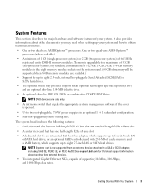
... 2 GB (two-processor systems) of supporting 10-Mbps, 100-Mbps, and 1000-Mbps data rates. Memory is opened. • Up to two hot-pluggable, 750-W power supplies in the eight memory module sockets on the system board. (64 GB of cache memory and a RAID battery, which supports up your system. See support....dell.com for an optional half-height tape backup unit (TBU) and an optional slim-line 1.44-MB diskette drive. • An optional slim-line IDE ...
... 2 GB (two-processor systems) of supporting 10-Mbps, 100-Mbps, and 1000-Mbps data rates. Memory is opened. • Up to two hot-pluggable, 750-W power supplies in the eight memory module sockets on the system board. (64 GB of cache memory and a RAID battery, which supports up your system. See support....dell.com for an optional half-height tape backup unit (TBU) and an optional slim-line 1.44-MB diskette drive. • An optional slim-line IDE ...
Getting Started Guide
Page 10
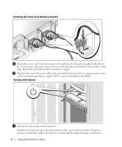
... system and the monitor. Installing the Power Cord Retention Bracket Attach the power cord retention bracket on the right bend of the power cables into a loop as an uninterrupted power supply (UPS) or a power distribution unit (PDU). Plug the other end of the power supply handle. With the bezel removed, press the power button on the system and monitor...
... system and the monitor. Installing the Power Cord Retention Bracket Attach the power cord retention bracket on the right bend of the power cables into a loop as an uninterrupted power supply (UPS) or a power distribution unit (PDU). Plug the other end of the power supply handle. With the bezel removed, press the power button on the system and monitor...
Getting Started Guide
Page 13
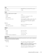
... of 10°C per hour NOTE: For altitudes above 2950 feet, the maximum operating temperature is derated 1ºF/550 ft. VGA connector 32 MB Power AC power supply (per power supply) Wattage Voltage Heat dissipation Maximum inrush current Batteries System battery RAID battery (optional) 750 W 85-264 VAC, autoranging, 47-63 Hz 2697 BTU... ATI ES1000 video controller; Temperature Operating 10° to 35°C (50° to 149°F) with a maximum temperature gradation of 20°C per power supply for specific system configurations, see www.dell.com/environmental_datasheets.
... of 10°C per hour NOTE: For altitudes above 2950 feet, the maximum operating temperature is derated 1ºF/550 ft. VGA connector 32 MB Power AC power supply (per power supply) Wattage Voltage Heat dissipation Maximum inrush current Batteries System battery RAID battery (optional) 750 W 85-264 VAC, autoranging, 47-63 Hz 2697 BTU... ATI ES1000 video controller; Temperature Operating 10° to 35°C (50° to 149°F) with a maximum temperature gradation of 20°C per power supply for specific system configurations, see www.dell.com/environmental_datasheets.
Hardware Owner's Manual
Page 4
... a Hot-Plug Hard Drive 58 Replacing a Hard-Drive Carrier 59 Removing a Hard Drive From a Hard-Drive Carrier 59 Installing a Hard Drive Into a Drive Carrier 59 Power Supplies 60 Removing a Power Supply 61 Replacing a Power Supply 62 Removing the Power Supply Blank 62 Installing the Power Supply Blank 63 4 Contents
... a Hot-Plug Hard Drive 58 Replacing a Hard-Drive Carrier 59 Removing a Hard Drive From a Hard-Drive Carrier 59 Installing a Hard Drive Into a Drive Carrier 59 Power Supplies 60 Removing a Power Supply 61 Replacing a Power Supply 62 Removing the Power Supply Blank 62 Installing the Power Supply Blank 63 4 Contents
Hardware Owner's Manual
Page 7
... Troubleshooting a Serial I/O Device 119 Troubleshooting a USB Device 119 Troubleshooting a NIC 120 Troubleshooting a Wet System 120 Troubleshooting a Damaged System 121 Troubleshooting the System Battery 122 Troubleshooting Power Supplies 122 Troubleshooting System Cooling Problems 123 Troubleshooting a Fan 124 Troubleshooting System Memory 124 Troubleshooting a Diskette Drive 126 Troubleshooting an Optical Drive 127 Troubleshooting a Tape Drive...
... Troubleshooting a Serial I/O Device 119 Troubleshooting a USB Device 119 Troubleshooting a NIC 120 Troubleshooting a Wet System 120 Troubleshooting a Damaged System 121 Troubleshooting the System Battery 122 Troubleshooting Power Supplies 122 Troubleshooting System Cooling Problems 123 Troubleshooting a Fan 124 Troubleshooting System Memory 124 Troubleshooting a Diskette Drive 126 Troubleshooting an Optical Drive 127 Troubleshooting a Tape Drive...
Hardware Owner's Manual
Page 13
... driver errors when using certain operating systems. This button can take as long as 30 seconds to the system is not accessible. The power button controls the DC power supply output to do so by qualified support personnel or by the operating system's documentation. Front-Panel Features and Indicators Figure 1-1 shows the controls...
... driver errors when using certain operating systems. This button can take as long as 30 seconds to the system is not accessible. The power button controls the DC power supply output to do so by qualified support personnel or by the operating system's documentation. Front-Panel Features and Indicators Figure 1-1 shows the controls...
Hardware Owner's Manual
Page 17
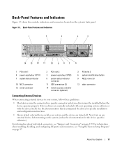
... Back-Panel Features and Indicators 1 2 3 4 5 PCI 1 PCI 2 PCI 3 Gb 2 Gb 1 14 13 12 11 10 9 87 6 1 PCIe slot 1 4 power supply bay 1 (PS1) 7 system status indicator 10 NIC1 connector 13 serial connector 2 PCIe slot 2 5 power supply bay 2 (PS2) 8 system status indicator connector 11 USB connectors (2) 14 remote access controller connector (optional) 3 PCIe slot 3 6 system identification...
... Back-Panel Features and Indicators 1 2 3 4 5 PCI 1 PCI 2 PCI 3 Gb 2 Gb 1 14 13 12 11 10 9 87 6 1 PCIe slot 1 4 power supply bay 1 (PS1) 7 system status indicator 10 NIC1 connector 13 serial connector 2 PCIe slot 2 5 power supply bay 2 (PS2) 8 system status indicator connector 11 USB connectors (2) 14 remote access controller connector (optional) 3 PCIe slot 3 6 system identification...

Hardware Owner's Manual
Page 18
... 1-4. Power supply fault Amber indicates a problem with the power supply. Redundant Power Supply Indicators 1 2 3 1 power supply status 2 power supply fault 3 AC line status 18 About Your System Redundant Power Supply Indicators Indicator Function Power supply status Green indicates that a valid AC source is connected to the system from the system's power supplies. The indicators on the front panel controls the power to the power supply. Table 1-4 lists the power supply indicator...
... 1-4. Power supply fault Amber indicates a problem with the power supply. Redundant Power Supply Indicators 1 2 3 1 power supply status 2 power supply fault 3 AC line status 18 About Your System Redundant Power Supply Indicators Indicator Function Power supply status Green indicates that a valid AC source is connected to the system from the system's power supplies. The indicators on the front panel controls the power to the power supply. Table 1-4 lists the power supply indicator...

Hardware Owner's Manual
Page 21
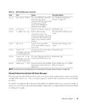
...voltage range See "Getting Help" on page 123. Cooling Problems" on page 147. 2.5V PwrGd 2.5V voltage regulator has failed. If removed, reinsert the power supply into the bay and reconnect to connector. RPM Fan ## RPM of multiple voltage regulators used in the video and LOM circuitry. PCI riser has failed.... CPU VTT PwrGd Processor # VTT voltage has exceeded the allowable voltage range See "Getting Help" on . failed. The specified power supply has failed or has been removed from the bay while the system was on page 147. Table 1-6.
...voltage range See "Getting Help" on page 123. Cooling Problems" on page 147. 2.5V PwrGd 2.5V voltage regulator has failed. If removed, reinsert the power supply into the bay and reconnect to connector. RPM Fan ## RPM of multiple voltage regulators used in the video and LOM circuitry. PCI riser has failed.... CPU VTT PwrGd Processor # VTT voltage has exceeded the allowable voltage range See "Getting Help" on . failed. The specified power supply has failed or has been removed from the bay while the system was on page 147. Table 1-6.
Hardware Owner's Manual
Page 23
... "Getting Help" on page 122. processor initialization error. specified power supply is improperly installed or faulty. specified power Supplies" on page 122. specified power supply is improperly installed or faulty. supply is no See "Troubleshooting Power longer redundant. PS Redundancy The power supply subsystem is improperly installed or faulty. See "Troubleshooting Power Supplies" on page 122. If the problem persists, see "Troubleshooting...
... "Getting Help" on page 122. processor initialization error. specified power supply is improperly installed or faulty. specified power Supplies" on page 122. specified power supply is improperly installed or faulty. supply is no See "Troubleshooting Power longer redundant. PS Redundancy The power supply subsystem is improperly installed or faulty. See "Troubleshooting Power Supplies" on page 122. If the problem persists, see "Troubleshooting...
Hardware Owner's Manual
Page 27
... specify a very precise fault condition that the memory had too many errors. See "RAID battery has less than 24 hours of events, and is a failing power supply. About Your System 27 I1910 Intrusion System cover has been removed. Check the SEL for details on page 175. The fourth message displays as the...
... specify a very precise fault condition that the memory had too many errors. See "RAID battery has less than 24 hours of events, and is a failing power supply. About Your System 27 I1910 Intrusion System cover has been removed. Check the SEL for details on page 175. The fourth message displays as the...
Hardware Owner's Manual
Page 51
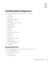
Installing System Components This section describes how to install the following system components: • Hard drives • Power supplies • System fans • SAS controller daughter card • RAID battery • Internal USB memory key connector • Expansion cards • Expansion card cage • ...
Installing System Components This section describes how to install the following system components: • Hard drives • Power supplies • System fans • SAS controller daughter card • RAID battery • Internal USB memory key connector • Expansion cards • Expansion card cage • ...
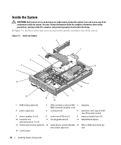
Hardware Owner's Manual
Page 52
... of the components inside the computer, and protecting against electrostatic discharge. Inside the System 6 2 1 5 4 3 7 8 16 9 10 11 15 12 14 13 1 RAID battery (optional) 2 4 power supply bay 5 7 power supplies (1 or 2) 8 10 heatsinks and 11 microprocessors (1 or 2) 13 slimline optical drive (optional) 14 16 control panel SAS controller or optional SAS 3 RAID controller daughter card...
... of the components inside the computer, and protecting against electrostatic discharge. Inside the System 6 2 1 5 4 3 7 8 16 9 10 11 15 12 14 13 1 RAID battery (optional) 2 4 power supply bay 5 7 power supplies (1 or 2) 8 10 heatsinks and 11 microprocessors (1 or 2) 13 slimline optical drive (optional) 14 16 control panel SAS controller or optional SAS 3 RAID controller daughter card...
Hardware Owner's Manual
Page 55
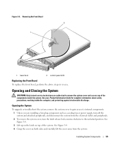
... system. Installing System Components 55 Opening and Closing the System CAUTION: Only trained service technicians are installing a hot-plug component such as a cooling fan or power supply, turn off the system and attached peripherals, and disconnect the system from the system. See Figure 3-4. 3 Lift up on the latch on both sides and...
... system. Installing System Components 55 Opening and Closing the System CAUTION: Only trained service technicians are installing a hot-plug component such as a cooling fan or power supply, turn off the system and attached peripherals, and disconnect the system from the system. See Figure 3-4. 3 Lift up on the latch on both sides and...
Hardware Owner's Manual
Page 60
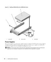
If two power supplies are installed, the second power supply serves as a redundant, hot-plug power source. NOTICE: To ensure proper system cooling, the power supply blank must be installed on page 63. 60 Installing System Components See "Installing the Power Supply Blank" on the unoccupied power supply bay in the left power supply bay (1). If only one or two power supplies rated at an output...
If two power supplies are installed, the second power supply serves as a redundant, hot-plug power source. NOTICE: To ensure proper system cooling, the power supply blank must be installed on page 63. 60 Installing System Components See "Installing the Power Supply Blank" on the unoccupied power supply bay in the left power supply bay (1). If only one or two power supplies rated at an output...


