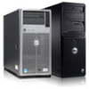
Service Manual
Page 6
... supply, 1-10 cables, 1-12 connectors, 1-10 DC voltage ranges, 1-10 illustrated, 1-12 power distribution diagram, 1-13 removal, 4-12 precautionary measures, 4-2 R reset button, 1-3 resource conflicts, eliminating, 2-5 2 Dell PowerEdge 2100/180 and 2100/200 Systems Service Manual
... supply, 1-10 cables, 1-12 connectors, 1-10 DC voltage ranges, 1-10 illustrated, 1-12 power distribution diagram, 1-13 removal, 4-12 precautionary measures, 4-2 R reset button, 1-3 resource conflicts, eliminating, 2-5 2 Dell PowerEdge 2100/180 and 2100/200 Systems Service Manual

Service Manual
Page 15
... basic computer system. The microprocessor module is installed in this man- PowerEdge 2100 systems incorporate the highperformance peripheral component interconnect (PCI) local bus as well as follows: • Dell PowerEdge 2100/180 system - 180 MHz derived from a system clock frequency of 60 MHz • Dell PowerEdge 2100/200 system - 200 MHz derived from a system clock frequency of the system clock...
... basic computer system. The microprocessor module is installed in this man- PowerEdge 2100 systems incorporate the highperformance peripheral component interconnect (PCI) local bus as well as follows: • Dell PowerEdge 2100/180 system - 180 MHz derived from a system clock frequency of 60 MHz • Dell PowerEdge 2100/200 system - 200 MHz derived from a system clock frequency of the system clock...
Service Manual
Page 16
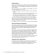
... server management circuitry that monitors operation of the expansion-card slots are briefly described in this chapter. 1-2 Dell PowerEdge 2100/180 and 2100/200 Systems Service Manual tion about QUICK TEST, see "Technical Specifications" found in a traditional personal computer, Dell PowerEdge 2100 systems include the following new and/or advanced features: • 256 KB of cache memory internal...
... server management circuitry that monitors operation of the expansion-card slots are briefly described in this chapter. 1-2 Dell PowerEdge 2100/180 and 2100/200 Systems Service Manual tion about QUICK TEST, see "Technical Specifications" found in a traditional personal computer, Dell PowerEdge 2100 systems include the following new and/or advanced features: • 256 KB of cache memory internal...
Service Manual
Page 18
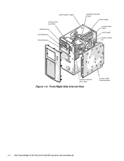
Front/Right Side Internal View system board mounting plate 1-4 Dell PowerEdge 2100/180 and 2100/200 Systems Service Manual system power supply control panel assembly diskette drive CD-ROM drive third drive bay diskette controller cable power cables control panel cable SCSI cable system cooling fan internal hard-disk drive cage Figure 1-3.
Front/Right Side Internal View system board mounting plate 1-4 Dell PowerEdge 2100/180 and 2100/200 Systems Service Manual system power supply control panel assembly diskette drive CD-ROM drive third drive bay diskette controller cable power cables control panel cable SCSI cable system cooling fan internal hard-disk drive cage Figure 1-3.
Service Manual
Page 20
... into the memory controller on the system board (see Figure 1-11). The EISA Configuration Utility included with the Intel LANDesk® Server Management suite. 1-6 Dell PowerEdge 2100/180 and 2100/200 Systems Service Manual After all legacy cards have been configured with the smaller capacity DIMMs installed in Chapter 4 for using it to 256 MB...
... into the memory controller on the system board (see Figure 1-11). The EISA Configuration Utility included with the Intel LANDesk® Server Management suite. 1-6 Dell PowerEdge 2100/180 and 2100/200 Systems Service Manual After all legacy cards have been configured with the smaller capacity DIMMs installed in Chapter 4 for using it to 256 MB...
Service Manual
Page 22
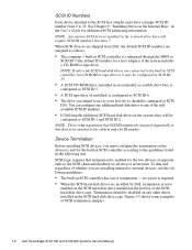
...internal or external devices, use as your boot device should be disabled on any of the stillavailable SCSI ID numbers. • If Dell installs additional SCSI hard-disk drives in the system, they will require SCSI ID numbers less than 7. You can configure any additional ...in the User's Guide for the two devices at opposite ends of SCSI termination jumpers. 1-8 Dell PowerEdge 2100/180 and 2100/200 Systems Service Manual See Chapter 9, "Installing Drives in the Internal Bays" in order by Dell, termination is configured through the BIOS as SCSI ID 1 and SCSI ID 2. SCSI logic...
...internal or external devices, use as your boot device should be disabled on any of the stillavailable SCSI ID numbers. • If Dell installs additional SCSI hard-disk drives in the system, they will require SCSI ID numbers less than 7. You can configure any additional ...in the User's Guide for the two devices at opposite ends of SCSI termination jumpers. 1-8 Dell PowerEdge 2100/180 and 2100/200 Systems Service Manual See Chapter 9, "Installing Drives in the Internal Bays" in order by Dell, termination is configured through the BIOS as SCSI ID 1 and SCSI ID 2. SCSI logic...

Service Manual
Page 24
... 230 W. Pin Assignments for the DC Power Connectors The power-supply output voltages can operate from an AC power source of the connectors. 1-10 Dell PowerEdge 2100/180 and 2100/200 Systems Service Manual Figures 1-6, 1-7, and 1-8 show the wire side of 115 VAC at 60 Hz or 230 VAC at the back (wire side) of...
... 230 W. Pin Assignments for the DC Power Connectors The power-supply output voltages can operate from an AC power source of the connectors. 1-10 Dell PowerEdge 2100/180 and 2100/200 Systems Service Manual Figures 1-6, 1-7, and 1-8 show the wire side of 115 VAC at 60 Hz or 230 VAC at the back (wire side) of...

Service Manual
Page 26
DC Power Cables 1-12 Dell PowerEdge 2100/180 and 2100/200 Systems Service Manual DC Power Connectors P7 DC Power Distribution Figures 1-9 and 1-10 provide the following information about DC power distribution: • Power-supply connector identification • Power cable connections for diskette, tape, CD-ROM, and hard-disk drives • Power distribution to sockets and connectors on the system board P1 P4 P5 P7 P6 P3 P2 Figure 1-9. P7 1 2 34 5 6 +3.3 VDC (blue/white) +3.3 VDC (blue/white) +3.3 VDC (blue/white) common (black) common (black) common (black) Figure 1-8.
DC Power Cables 1-12 Dell PowerEdge 2100/180 and 2100/200 Systems Service Manual DC Power Connectors P7 DC Power Distribution Figures 1-9 and 1-10 provide the following information about DC power distribution: • Power-supply connector identification • Power cable connections for diskette, tape, CD-ROM, and hard-disk drives • Power distribution to sockets and connectors on the system board P1 P4 P5 P7 P6 P3 P2 Figure 1-9. P7 1 2 34 5 6 +3.3 VDC (blue/white) +3.3 VDC (blue/white) +3.3 VDC (blue/white) common (black) common (black) common (black) Figure 1-8.

Service Manual
Page 28
System Board Components 1-14 Dell PowerEdge 2100/180 and 2100/200 Systems Service Manual System Board Layout The subsections that follow provide service-related information about the system board components. fan connector (FAN) integrated SCSI port ...
System Board Components 1-14 Dell PowerEdge 2100/180 and 2100/200 Systems Service Manual System Board Layout The subsections that follow provide service-related information about the system board components. fan connector (FAN) integrated SCSI port ...
Service Manual
Page 30
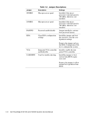
.... Integrated VGA controller enable/disable Used for trouble shooting Remove the jumper and use the EISA Configuration Utility to boot system from BIOS. 1-16 Dell PowerEdge 2100/180 and 2100/200 Systems Service Manual Password enable/disable Jumper installed to enable the integrated VGA controller. Jumper Descriptions Description Settings Microprocessor speed Installed if the microprocessor...
.... Integrated VGA controller enable/disable Used for trouble shooting Remove the jumper and use the EISA Configuration Utility to boot system from BIOS. 1-16 Dell PowerEdge 2100/180 and 2100/200 Systems Service Manual Password enable/disable Jumper installed to enable the integrated VGA controller. Jumper Descriptions Description Settings Microprocessor speed Installed if the microprocessor...
Service Manual
Page 33
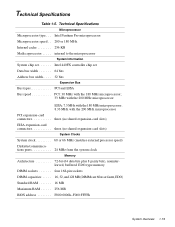
Intel Pentium Pro microprocessor Microprocessor speed . . 200 or 180 MHz Internal cache 256 KB Math coprocessor . . . . . Technical Specifications Table 1-5. internal to the microprocessor System Information System chip set Intel 440FX controller chip ... Bus types PCI and EISA Bus speed PCI: 30 MHz with the 180 MHz microprocessor; 33 MHz with the 200 MHz microprocessor EISA: 7.5 MHz with the 180 MHz microprocessor; 8.33 MHz with the 200 MHz microprocessor PCI expansion-card connectors three (no shared expansion-card slots) EISA expansion-card connectors three (no...
Intel Pentium Pro microprocessor Microprocessor speed . . 200 or 180 MHz Internal cache 256 KB Math coprocessor . . . . . Technical Specifications Table 1-5. internal to the microprocessor System Information System chip set Intel 440FX controller chip ... Bus types PCI and EISA Bus speed PCI: 30 MHz with the 180 MHz microprocessor; 33 MHz with the 200 MHz microprocessor EISA: 7.5 MHz with the 180 MHz microprocessor; 8.33 MHz with the 200 MHz microprocessor PCI expansion-card connectors three (no shared expansion-card slots) EISA expansion-card connectors three (no...

Service Manual
Page 34
... indicator green LED Diskette-drive access indicator green LED Hard-disk drive access indicator green LED CD-ROM drive access indicator green LED 1-20 Dell PowerEdge 2100/180 and 2100/200 Systems Service Manual Technical Specifications (Continued) Integrated SCSI Controller Type Adaptec AIC-7880 ultra wide SCSI controller with integrated 68-pin SCSI connector on...
... indicator green LED Diskette-drive access indicator green LED Hard-disk drive access indicator green LED CD-ROM drive access indicator green LED 1-20 Dell PowerEdge 2100/180 and 2100/200 Systems Service Manual Technical Specifications (Continued) Integrated SCSI Controller Type Adaptec AIC-7880 ultra wide SCSI controller with integrated 68-pin SCSI connector on...

Service Manual
Page 35
...; to 95°F) Storage 40° to 65°C (-40° to 149°F) Relative humidity . . 8% to 80% (noncondensing) Maximum vibration: Operating 0.25 G at 3 to 200 Hz for 2 ms; square wave form: 27 g for 15 ms Altitude: Operating 16 to 3048 m (-50 to 10,000 ft) Storage 16 to 10,600... m (-50 to 200 Hz for 30 min Maximum shock: Operating half-sine wave form: 50 G for 2 ms Storage half-sine wave form: 110 G for 30 min Storage 0.5 G at...
...; to 95°F) Storage 40° to 65°C (-40° to 149°F) Relative humidity . . 8% to 80% (noncondensing) Maximum vibration: Operating 0.25 G at 3 to 200 Hz for 2 ms; square wave form: 27 g for 15 ms Altitude: Operating 16 to 3048 m (-50 to 10,000 ft) Storage 16 to 10,600... m (-50 to 200 Hz for 30 min Maximum shock: Operating half-sine wave form: 50 G for 2 ms Storage half-sine wave form: 110 G for 30 min Storage 0.5 G at...
Service Manual
Page 38
... the system unit as well as to the interface connector on the back panel or to a video expansion card and to replace the keyboard. 2-2 Dell PowerEdge 2100/180 and 2100/200 Systems Service Manual The captive screws that all power cables are identical except for the monitor. 8. If one of the serial port connectors, and...
... the system unit as well as to the interface connector on the back panel or to a video expansion card and to replace the keyboard. 2-2 Dell PowerEdge 2100/180 and 2100/200 Systems Service Manual The captive screws that all power cables are identical except for the monitor. 8. If one of the serial port connectors, and...
Service Manual
Page 40
... power cables from the drives. If a system error message is not a beep code. 5. Insert another copy of these steps: 1. Remove the system unit cover. 2-4 Dell PowerEdge 2100/180 and 2100/200 Systems Service Manual No. If either of the diagnostics diskette into the diskette drive, and reboot the system. This single beep is normal and...
... power cables from the drives. If a system error message is not a beep code. 5. Insert another copy of these steps: 1. Remove the system unit cover. 2-4 Dell PowerEdge 2100/180 and 2100/200 Systems Service Manual No. If either of the diagnostics diskette into the diskette drive, and reboot the system. This single beep is normal and...
Service Manual
Page 42
...use a backup copy of the system • RUN SPECIFIC TESTS - If no errors are found in the Diagnostics and Troubleshooting Guide. 2-6 Dell PowerEdge 2100/180 and 2100/200 Systems Service Manual If a main memory error is needed to isolate a failure • RUN ALL TESTS - Runs all tests for a ...thorough test of the diagnostics diskette when servicing a user's system. Dell recommends that users make several copies of this chapter or the ...
...use a backup copy of the system • RUN SPECIFIC TESTS - If no errors are found in the Diagnostics and Troubleshooting Guide. 2-6 Dell PowerEdge 2100/180 and 2100/200 Systems Service Manual If a main memory error is needed to isolate a failure • RUN ALL TESTS - Runs all tests for a ...thorough test of the diagnostics diskette when servicing a user's system. Dell recommends that users make several copies of this chapter or the ...
Service Manual
Page 44
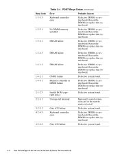
.... Unexpected interrupt Improperly seated expansion card or the system needs rebooted. Reseat the DIMMs or replace the system board. Gate A20 failure Defective system board. 3-2 Dell PowerEdge 2100/180 and 2100/200 Systems Service Manual
.... Unexpected interrupt Improperly seated expansion card or the system needs rebooted. Reseat the DIMMs or replace the system board. Gate A20 failure Defective system board. 3-2 Dell PowerEdge 2100/180 and 2100/200 Systems Service Manual

Service Manual
Page 46
... error A cable may be loose, the keyboard may have been accidentally installed. Verify that the total installed DIMM memory does not exceed 256 MB. 3-4 Dell PowerEdge 2100/180 and 2100/200 Systems Service Manual System Error Messages (Continued) Message Definition Probable Causes Operating system not found The system did not find a bootable operating system. Defective...
... error A cable may be loose, the keyboard may have been accidentally installed. Verify that the total installed DIMM memory does not exceed 256 MB. 3-4 Dell PowerEdge 2100/180 and 2100/200 Systems Service Manual System Error Messages (Continued) Message Definition Probable Causes Operating system not found The system did not find a bootable operating system. Defective...

Service Manual
Page 50
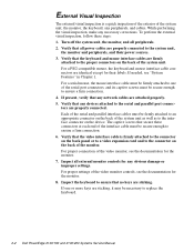
.... Disconnect the computer and any attached peripherals from their power sources to discharge any of the computer to reduce the potential for your body. 4-2 Dell PowerEdge 2100/180 and 2100/200 Systems Service Manual If a wrist grounding strap is not available, touch the fan guard or some other unpainted metal surface on the computer chassis...
.... Disconnect the computer and any attached peripherals from their power sources to discharge any of the computer to reduce the potential for your body. 4-2 Dell PowerEdge 2100/180 and 2100/200 Systems Service Manual If a wrist grounding strap is not available, touch the fan guard or some other unpainted metal surface on the computer chassis...

Service Manual
Page 52
As you pry the front bezel loose, pry at different points around the bezel to keep the opening between the front bezel and the computer chassis equal on all sides to prevent damage to the bezel alignment pins. 4-4 Dell PowerEdge 2100/180 and 2100/200 Systems Service Manual Front Bezel Removal To remove the front bezel, follow these steps: 1. Front Bezel retaining holes (6) retaining clips (6) alignment holes (5) alignment pins (5) Figure 4-2. Pry the front bezel loose with your finger tips and remove it from the chassis. Remove the computer cover. 2.
As you pry the front bezel loose, pry at different points around the bezel to keep the opening between the front bezel and the computer chassis equal on all sides to prevent damage to the bezel alignment pins. 4-4 Dell PowerEdge 2100/180 and 2100/200 Systems Service Manual Front Bezel Removal To remove the front bezel, follow these steps: 1. Front Bezel retaining holes (6) retaining clips (6) alignment holes (5) alignment pins (5) Figure 4-2. Pry the front bezel loose with your finger tips and remove it from the chassis. Remove the computer cover. 2.