Reference and Installation Guide (.pdf)
Page 7
...; Users who add or remove an Industry-Standard Architecture (ISA) expansion card should read the rest of system features, instructions on installing and configuring drivers and utilities, information on connecting the system to a network, configuring the optional network interface controller (NIC), installing drivers for the NIC, and running the NIC diagnostics. • Chapter 5, "Working Inside Your Computer," Chapter 6, "Installing System Board Options," and Chapter 7, "Installing Drives," are interested in accordance with your system: • The Getting Started...
...; Users who add or remove an Industry-Standard Architecture (ISA) expansion card should read the rest of system features, instructions on installing and configuring drivers and utilities, information on connecting the system to a network, configuring the optional network interface controller (NIC), installing drivers for the NIC, and running the NIC diagnostics. • Chapter 5, "Working Inside Your Computer," Chapter 6, "Installing System Board Options," and Chapter 7, "Installing Drives," are interested in accordance with your system: • The Getting Started...

Reference and Installation Guide (.pdf)
Page 13
... NetWare Environment 4-2 Using Install in a Non-NetWare Environment 4-3 Using Install to Change Configuration Settings 4-3 Installing a Network Driver 4-4 NetWare 4.0 Server Drivers 4-4 Running the NIC Diagnostics 4-5 Running the Group 1 Tests 4-5 Running the Group 3 Test 4-5 Setting Up an Echo Server 4-6 Running the Diagnostic Tests 4-6 Changing the Test Parameters 4-6 What to Do If a Test Fails 4-6 Chapter 5 Working Inside Your Computer 5-1 Before You Begin 5-1 Safety First-For You and Your Computer 5-1 Unpacking Your Hardware Option 5-2 Removing the Computer Cover 5-2 xv
... NetWare Environment 4-2 Using Install in a Non-NetWare Environment 4-3 Using Install to Change Configuration Settings 4-3 Installing a Network Driver 4-4 NetWare 4.0 Server Drivers 4-4 Running the NIC Diagnostics 4-5 Running the Group 1 Tests 4-5 Running the Group 3 Test 4-5 Setting Up an Echo Server 4-6 Running the Diagnostic Tests 4-6 Changing the Test Parameters 4-6 What to Do If a Test Fails 4-6 Chapter 5 Working Inside Your Computer 5-1 Before You Begin 5-1 Safety First-For You and Your Computer 5-1 Unpacking Your Hardware Option 5-2 Removing the Computer Cover 5-2 xv
Reference and Installation Guide (.pdf)
Page 20
... port is configured using the 1-2 Dell OptiPlex Gs and Gs+ Low-Profile Systems Reference and Installation Guide NOTE: The system's BIOS resides in this program, see your online System User's Guide. • Video drivers for your system. Each interface supports extremely highcapacity EIDE drives, as well as devices such as maximizing your system and enhance the operation of screws for connecting external devices. For more information, see your system to PCI and Plug...
... port is configured using the 1-2 Dell OptiPlex Gs and Gs+ Low-Profile Systems Reference and Installation Guide NOTE: The system's BIOS resides in this program, see your online System User's Guide. • Video drivers for your system. Each interface supports extremely highcapacity EIDE drives, as well as devices such as maximizing your system and enhance the operation of screws for connecting external devices. For more information, see your system to PCI and Plug...
Reference and Installation Guide (.pdf)
Page 21
... the Diagnostics and Troubleshooting Guide. • Network device drivers for your system. For more about DMI by double-clicking the DMI icon in the Windows Control Panel (located in the Main program group or folder). • The Dell Inspector utility, which uses DMI support to reclaim space on your system's hard-disk drive. Using the Optional Floor Stand An optional floor stand is available for technical assistance or if you set ) to display...
... the Diagnostics and Troubleshooting Guide. • Network device drivers for your system. For more about DMI by double-clicking the DMI icon in the Windows Control Panel (located in the Main program group or folder). • The Dell Inspector utility, which uses DMI support to reclaim space on your system's hard-disk drive. Using the Optional Floor Stand An optional floor stand is available for technical assistance or if you set ) to display...
Reference and Installation Guide (.pdf)
Page 22
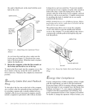
...) securing button locking device and associated key. padlock ring Figure 1-1. To remove the floor stand, turn the computer over so the floor stand is at the top. The padlock ring allows you 1-4 Dell OptiPlex Gs and Gs+ Low-Profile Systems Reference and Installation Guide To use the padlock ring, insert a commercially available padlock through the ring and lock the padlock. Security Cable Slot and...
...) securing button locking device and associated key. padlock ring Figure 1-1. To remove the floor stand, turn the computer over so the floor stand is at the top. The padlock ring allows you 1-4 Dell OptiPlex Gs and Gs+ Low-Profile Systems Reference and Installation Guide To use the padlock ring, insert a commercially available padlock through the ring and lock the padlock. Security Cable Slot and...
Reference and Installation Guide (.pdf)
Page 30
... a memory expansion card that requires special addressing. This option does not affect the operation of memory available as extended memory. You should not enable the reserved memory feature unless you are : • NOT ENABLED (the default option) • ENABLED • DISABLED BY JUMPER NOTE: Read "Using the System Password Feature" found later in this chapter for detailed instructions on disabling a forgotten system password. 2-6 Dell OptiPlex Gs and Gs+ Low-Profile Systems Reference and Installation Guide...
... a memory expansion card that requires special addressing. This option does not affect the operation of memory available as extended memory. You should not enable the reserved memory feature unless you are : • NOT ENABLED (the default option) • ENABLED • DISABLED BY JUMPER NOTE: Read "Using the System Password Feature" found later in this chapter for detailed instructions on disabling a forgotten system password. 2-6 Dell OptiPlex Gs and Gs+ Low-Profile Systems Reference and Installation Guide...
Reference and Installation Guide (.pdf)
Page 33
...'s optional network interface controller (NIC). Mouse MOUSE enables or disables the system's built-in an expansion slot. With AUTO selected (the default option), the system turns off . As part of peripheral device connected to the parallel port. Your system also supports ECP mode, which shares IRQ3 with the device. Serial Port 1 and Serial Port 2 SERIAL PORT 1 and SERIAL PORT 2 configure the system's built-in an Using the System Setup Program 2-9 If you set a serial port to AUTO and add an expansion card containing a port configured to...
...'s optional network interface controller (NIC). Mouse MOUSE enables or disables the system's built-in an expansion slot. With AUTO selected (the default option), the system turns off . As part of peripheral device connected to the parallel port. Your system also supports ECP mode, which shares IRQ3 with the device. Serial Port 1 and Serial Port 2 SERIAL PORT 1 and SERIAL PORT 2 configure the system's built-in an Using the System Setup Program 2-9 If you set a serial port to AUTO and add an expansion card containing a port configured to...
Reference and Installation Guide (.pdf)
Page 34
... diskette/tape drive controller as described in EIDE interface is your online System User's Guide. this category to change an existing system password, you for the system password just after the system boots. The service tag number is recognized by certain Dell support software, including the diagnostics software. • ASSET TAG displays the customer-programmable asset tag number for the data on Expanded Memory Specification (EMS) expansion cards. If your...
... diskette/tape drive controller as described in EIDE interface is your online System User's Guide. this category to change an existing system password, you for the system password just after the system boots. The service tag number is recognized by certain Dell support software, including the diagnostics software. • ASSET TAG displays the customer-programmable asset tag number for the data on Expanded Memory Specification (EMS) expansion cards. If your...
Reference and Installation Guide (.pdf)
Page 36
... normal operation of the System Setup screens. To assign a new password, follow the procedure in "Assigning a System Password" found earlier in this chapter. To change a jumper setting that you erase the system password at the same time. 2-12 Dell OptiPlex Gs and Gs+ Low-Profile Systems Reference and Installation Guide Must power down. When prompted, type the system password. 4. Confirm that the PASSWORD STATUS category is not displayed for a system password. 3. If...
... normal operation of the System Setup screens. To assign a new password, follow the procedure in "Assigning a System Password" found earlier in this chapter. To change a jumper setting that you erase the system password at the same time. 2-12 Dell OptiPlex Gs and Gs+ Low-Profile Systems Reference and Installation Guide Must power down. When prompted, type the system password. 4. Confirm that the PASSWORD STATUS category is not displayed for a system password. 3. If...
Reference and Installation Guide (.pdf)
Page 38
.../or setup password, you install a memory upgrade; Booting with the PSWD jumper plug removed erases the existing password(s). Booting your computer to receive an error message the first time you boot the system after you must replace the PSWD jumper plug. 6. it on . Replace the computer cover, reconnect the computer and peripherals to run the System Setup program, press the key. 2-14 Dell OptiPlex Gs and Gs+ Low-Profile Systems Reference and Installation Guide In that no passwords...
.../or setup password, you install a memory upgrade; Booting with the PSWD jumper plug removed erases the existing password(s). Booting your computer to receive an error message the first time you boot the system after you must replace the PSWD jumper plug. 6. it on . Replace the computer cover, reconnect the computer and peripherals to run the System Setup program, press the key. 2-14 Dell OptiPlex Gs and Gs+ Low-Profile Systems Reference and Installation Guide In that no passwords...
Reference and Installation Guide (.pdf)
Page 44
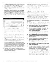
... must turn off the system and install, remove, or change and click the Options button located below the resource values (see "Adding a Listed Card" found earlier in step 2, click the OK button. NOTE: After modifying the system configuration, you have configuration files stored in the ICU. Adding an Unlisted Card Unlisted cards are available for the card. To add an unlisted card with the Specify Interrupt dialog box opened. 3-6 Dell OptiPlex Gs and Gs...
... must turn off the system and install, remove, or change and click the Options button located below the resource values (see "Adding a Listed Card" found earlier in step 2, click the OK button. NOTE: After modifying the system configuration, you have configuration files stored in the ICU. Adding an Unlisted Card Unlisted cards are available for the card. To add an unlisted card with the Specify Interrupt dialog box opened. 3-6 Dell OptiPlex Gs and Gs...
Reference and Installation Guide (.pdf)
Page 46
... the system configuration, you must enter the starting and ending addresses in the Configure Unlisted Card dialog box. Then continue with step 4 of a Plug and Play or PCI expansion card. do not proceed to accept the resource settings currently displayed. 8. allocate different resources to the cards currently in the ICU. 3-8 Dell OptiPlex Gs and Gs+ Low-Profile Systems Reference and Installation Guide Click the OK button. This procedure...
... the system configuration, you must enter the starting and ending addresses in the Configure Unlisted Card dialog box. Then continue with step 4 of a Plug and Play or PCI expansion card. do not proceed to accept the resource settings currently displayed. 8. allocate different resources to the cards currently in the ICU. 3-8 Dell OptiPlex Gs and Gs+ Low-Profile Systems Reference and Installation Guide Click the OK button. This procedure...
Reference and Installation Guide (.pdf)
Page 51
... lines should be in 10Base-T networks. Configure the NIC and install the network drivers by a separate network expansion card. Run the NIC diagnostics to a Network," for instructions. 3. The NIC, installed on " state.) • The green link integrity indicator lights up when there is used in a steady "on the system board for attaching an unshielded twisted pair (UTP) Ethernet cable, which is a valid 10Base-T connection between a workstation and a concentrator...
... lines should be in 10Base-T networks. Configure the NIC and install the network drivers by a separate network expansion card. Run the NIC diagnostics to a Network," for instructions. 3. The NIC, installed on " state.) • The green link integrity indicator lights up when there is used in a steady "on the system board for attaching an unshielded twisted pair (UTP) Ethernet cable, which is a valid 10Base-T connection between a workstation and a concentrator...
Reference and Installation Guide (.pdf)
Page 53
... chapter to complete the NIC configuration. Instructions for each configuration setting. Using Install to Change Configuration Settings In addition to disable Plug and Play support. To use the arrow keys to highlight the category for the configuration setting you should not need to change , and press . Using the Network Interface Controller 4-3 Press until the first option in the c:\dell\3com\qinstall\server subdirectory or on disabling Plug and Play support. Disable Plug and Play support unless your system is highlighted...
... chapter to complete the NIC configuration. Instructions for each configuration setting. Using Install to Change Configuration Settings In addition to disable Plug and Play support. To use the arrow keys to highlight the category for the configuration setting you should not need to change , and press . Using the Network Interface Controller 4-3 Press until the first option in the c:\dell\3com\qinstall\server subdirectory or on disabling Plug and Play support. Disable Plug and Play support unless your system is highlighted...
Reference and Installation Guide (.pdf)
Page 78
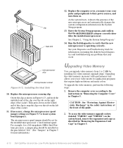
... System Setup program. 13. Replace the computer cover, reconnect your Diagnostics and Troubleshooting Guide for more information.) Upgrading Video Memory You can upgrade video memory from 1 to locate system board jumpers). As the system boots, it detects the presence of the socket. 11. Upgrading the video memory increases video performance and allows you to their power sources, and turn them on the left edge of the new microprocessor and automatically changes the system configuration information...
... System Setup program. 13. Replace the computer cover, reconnect your Diagnostics and Troubleshooting Guide for more information.) Upgrading Video Memory You can upgrade video memory from 1 to locate system board jumpers). As the system boots, it detects the presence of the socket. 11. Upgrading the video memory increases video performance and allows you to their power sources, and turn them on the left edge of the new microprocessor and automatically changes the system configuration information...
Reference and Installation Guide (.pdf)
Page 87
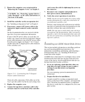
... computer cover. 6. Connect the tape drive's interface cable to its own dedicated controller card. secure the cable by touching an unpainted metal surface on the back of the way to the 4-pin power input connector on installing, partitioning, and formatting EIDE hard-disk drives. NOTE: You do not need to update the system configuration information for the fan and cooling vents. 5. After you install a tape drive, refer to make a backup of the controller card; Installing...
... computer cover. 6. Connect the tape drive's interface cable to its own dedicated controller card. secure the cable by touching an unpainted metal surface on the back of the way to the 4-pin power input connector on installing, partitioning, and formatting EIDE hard-disk drives. NOTE: You do not need to update the system configuration information for the fan and cooling vents. 5. After you install a tape drive, refer to make a backup of the controller card; Installing...
Reference and Installation Guide (.pdf)
Page 92
... came with the host adapter card. 8. For additional instructions on the back of the header connector fits into a standard electrical wall outlet. If you are keyed for the fan or cooling vents. 7-12 Dell OptiPlex Gs and Gs+ Low-Profile Systems Reference and Installation Guide The connectors are installing an internal SCSI device, firmly press the SCSI cable's header connector onto the 50-pin connector on connecting SCSI devices, see the documentation...
... came with the host adapter card. 8. For additional instructions on the back of the header connector fits into a standard electrical wall outlet. If you are keyed for the fan or cooling vents. 7-12 Dell OptiPlex Gs and Gs+ Low-Profile Systems Reference and Installation Guide The connectors are installing an internal SCSI device, firmly press the SCSI cable's header connector onto the 50-pin connector on connecting SCSI devices, see the documentation...
Reference and Installation Guide (.pdf)
Page 111
... parts removed from Dell; Dell will repair or replace products covered under this warranty. sound cards; Dell owns all other storage device(s) in accordance with product instructions, failure to a Dell system through the DellWare program) are covered only during shipment. external devices (except as described in the continental U.S. Warranties and Return Policy C-1 accessories or parts added to perform required preventive maintenance, and problems caused by use an address in the following categories: software; Batteries...
... parts removed from Dell; Dell will repair or replace products covered under this warranty. sound cards; Dell owns all other storage device(s) in accordance with product instructions, failure to a Dell system through the DellWare program) are covered only during shipment. external devices (except as described in the continental U.S. Warranties and Return Policy C-1 accessories or parts added to perform required preventive maintenance, and problems caused by use an address in the following categories: software; Batteries...
Reference and Installation Guide (.pdf)
Page 112
.... You must report each replacement part for parts used to external causes, including accident, abuse, misuse, problems with electrical power, servicing not authorized by Dell and for your use of parts and components not supplied by this limited warranty. Dell is covered under this limited warranty when a part requires replacement. DELL'S RESPONSIBILITY FOR MALFUNCTIONS AND DEFECTS IN HARDWARE IS LIMITED TO REPAIR AND REPLACEMENT AS SET FORTH IN THIS WARRANTY STATEMENT...
.... You must report each replacement part for parts used to external causes, including accident, abuse, misuse, problems with electrical power, servicing not authorized by Dell and for your use of parts and components not supplied by this limited warranty. Dell is covered under this limited warranty when a part requires replacement. DELL'S RESPONSIBILITY FOR MALFUNCTIONS AND DEFECTS IN HARDWARE IS LIMITED TO REPAIR AND REPLACEMENT AS SET FORTH IN THIS WARRANTY STATEMENT...
Service Manual (.pdf)
Page 40
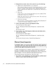
... the boot routine, troubleshoot the diskette drive or hard-disk drive subsystem, as a loose expansion card, cable connector, or mounting screw. Observe the monitor screen for any attached peripherals, and disconnect all open files and exited all the AC power cables from the drives. Yes. See "Running the Diskette-Based Diagnostics" found later in Chapter 1 to or from their power sources. 2-4 Dell OptiPlex Gs and Gs+ Systems Service Manual See "Running the Diskette-Based Diagnostics" found...
... the boot routine, troubleshoot the diskette drive or hard-disk drive subsystem, as a loose expansion card, cable connector, or mounting screw. Observe the monitor screen for any attached peripherals, and disconnect all open files and exited all the AC power cables from the drives. Yes. See "Running the Diskette-Based Diagnostics" found later in Chapter 1 to or from their power sources. 2-4 Dell OptiPlex Gs and Gs+ Systems Service Manual See "Running the Diskette-Based Diagnostics" found...


