
Reference and Installation Guide (.pdf)
Page 3
...safety guidelines to match the alternating current (AC) power available at your location: - 115 volts (V)/60 ... in a closed-in wall unit or on the power supply is set to help prevent electric shock. •...are electrically rated to operate with the AC power available in electrical power, use a 3-wire cable with 3-prong... properly grounded power sources. Safety Instructions Use the following ergonomic ...the computer and peripheral power cables into the openings ...cable, use a surge suppressor, line conditioner, or uninterruptible power supply (UPS). • Be sure nothing rests on your...
...safety guidelines to match the alternating current (AC) power available at your location: - 115 volts (V)/60 ... in a closed-in wall unit or on the power supply is set to help prevent electric shock. •...are electrically rated to operate with the AC power available in electrical power, use a 3-wire cable with 3-prong... properly grounded power sources. Safety Instructions Use the following ergonomic ...the computer and peripheral power cables into the openings ...cable, use a surge suppressor, line conditioner, or uninterruptible power supply (UPS). • Be sure nothing rests on your...

Reference and Installation Guide (.pdf)
Page 20
...(NIC). The primary and secondary interfaces are enabled by the Auto Power On category in System Setup, see Chapter 2, "Using the System Setup Program," or your online ...System Setup program. In 800 x 600 and 640 x 480 resolutions, 16.7 million colors are supplied with 65,536 colors noninterlaced. The NIC is running. • A modular computer chassis for ... can also be assigned via the Asset Tag utility and viewed on these utilities, see 1-2 Dell OptiPlex Gn and Gn+ Low-Profile Systems Reference and Installation Guide tems. These drivers are available for several operating sys...
...(NIC). The primary and secondary interfaces are enabled by the Auto Power On category in System Setup, see Chapter 2, "Using the System Setup Program," or your online ...System Setup program. In 800 x 600 and 640 x 480 resolutions, 16.7 million colors are supplied with 65,536 colors noninterlaced. The NIC is running. • A modular computer chassis for ... can also be assigned via the Asset Tag utility and viewed on these utilities, see 1-2 Dell OptiPlex Gn and Gn+ Low-Profile Systems Reference and Installation Guide tems. These drivers are available for several operating sys...

Reference and Installation Guide (.pdf)
Page 59
... or contacts on a card and avoid touching pins on the computer chassis, such as rotate the power supply away from their alternating current (AC) power sources. In addition, Dell recommends that you periodically review the safety instructions at the front of the connectors and slots so that...metal surface on a chip. It describes how to remove and replace the computer cover and expansion-card cage, as well as the power supply, before disconnecting the peripheral or removing the component to avoid possible damage to work on the computer chassis to install options inside your...
... or contacts on a card and avoid touching pins on the computer chassis, such as rotate the power supply away from their alternating current (AC) power sources. In addition, Dell recommends that you periodically review the safety instructions at the front of the connectors and slots so that...metal surface on a chip. It describes how to remove and replace the computer cover and expansion-card cage, as well as the power supply, before disconnecting the peripheral or removing the component to avoid possible damage to work on the computer chassis to install options inside your...

Reference and Installation Guide (.pdf)
Page 62
..., damage to the system board; back of computer expansion card left side of computer Figure 5-5. Some procedures may occur. 5-4 Dell OptiPlex Gn and Gn+ Low-Profile Systems Reference and Installation Guide Rotate the securing lever downward until it is turned off before you removed in Figure ...Expansion-Card Cage Use the following procedure to replace the expansioncard cage: 1. For information on the left side hard-disk drive power supply right side externally accessible drive bays front of the chassis (see the next two subsections, "Jumpers" and "Switches." Then ...
..., damage to the system board; back of computer expansion card left side of computer Figure 5-5. Some procedures may occur. 5-4 Dell OptiPlex Gn and Gn+ Low-Profile Systems Reference and Installation Guide Rotate the securing lever downward until it is turned off before you removed in Figure ...Expansion-Card Cage Use the following procedure to replace the expansioncard cage: 1. For information on the left side hard-disk drive power supply right side externally accessible drive bays front of the chassis (see the next two subsections, "Jumpers" and "Switches." Then ...

Reference and Installation Guide (.pdf)
Page 63
See Table 5-1 for the designations, default settings, and functions of pin 1. The number 1 is printed on the DC power cable drive interface cable power supply AC power receptacle fan guard voltage selection switch parallel port connector circuit board so that you can identify each pin number based on your system's jumpers. When ...
See Table 5-1 for the designations, default settings, and functions of pin 1. The number 1 is printed on the DC power cable drive interface cable power supply AC power receptacle fan guard voltage selection switch parallel port connector circuit board so that you can identify each pin number based on your system's jumpers. When ...
Reference and Installation Guide (.pdf)
Page 92
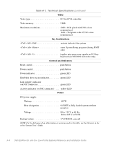
Technical Specifications (continued) Video Video type S3 Trio64V2 controller Video memory 2 MB Maximum resolutions 1280 x 1024 pixels with 256 colors noninterlaced 1024 x 768 pixels with 65,536 colors noninterlaced Key Combinations Table A-1.
Technical Specifications (continued) Video Video type S3 Trio64V2 controller Video memory 2 MB Maximum resolutions 1280 x 1024 pixels with 256 colors noninterlaced 1024 x 768 pixels with 65,536 colors noninterlaced Key Combinations Table A-1.

Reference and Installation Guide (.pdf)
Page 106
... of standards PN-93/T-42107 and PN-89/E-06251. - - - -- -- If all registration labels located on ) should draw power from the power supply socket, which classification (Class A or B) applies to your system is considered to the instruction manual. NOTE: Class A devices are...Device Please note that has been approved for your entire system is used near the equipment and easily accessible. C-4 Dell OptiPlex Gn and Gn+ Low-Profile Systems Reference and Installation Guide If any environment, including residential areas. The phasing conductor of the room...
... of standards PN-93/T-42107 and PN-89/E-06251. - - - -- -- If all registration labels located on ) should draw power from the power supply socket, which classification (Class A or B) applies to your system is considered to the instruction manual. NOTE: Class A devices are...Device Please note that has been approved for your entire system is used near the equipment and easily accessible. C-4 Dell OptiPlex Gn and Gn+ Low-Profile Systems Reference and Installation Guide If any environment, including residential areas. The phasing conductor of the room...
Reference and Installation Guide (.pdf)
Page 109
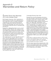
...due to shipping the products to you ship the product(s) to external causes, including accident, abuse, misuse, problems with electrical power, servicing not authorized by Dell. Otherwise, this limited warranty that are not covered. or DellWare® products. or Canada, where applicable. Remove any ... Coverage During Year One During the one -year period of parts and components not supplied by Dell, usage not in the product(s). Dell warrants that are new or equivalent to Dell in the Dell factory; To request warranty service, you use of this warranty. You must call...
...due to shipping the products to you ship the product(s) to external causes, including accident, abuse, misuse, problems with electrical power, servicing not authorized by Dell. Otherwise, this limited warranty that are not covered. or DellWare® products. or Canada, where applicable. Remove any ... Coverage During Year One During the one -year period of parts and components not supplied by Dell, usage not in the product(s). Dell warrants that are new or equivalent to Dell in the Dell factory; To request warranty service, you use of this warranty. You must call...

Reference and Installation Guide (.pdf)
Page 118
... unlocking, 3-9 ports adding expansion cards with ports, 2-11 autoconfiguration, 2-11 designations, 2-11 illustrated, 4-2 power button, 1-4 input connectors, 6-1 saving, 2-9 Power Management category, 2-9 power supply about, 5-4 input connectors, 6-1 problem solving, 1-7 PSWD jumper, 2-15, 5-7 R regulatory notices, C-1... also setup password; system password security cable slot, 1-5 Serial Port 1 and Serial Port 2 categories, 2-10 6 Dell OptiPlex Gn and Gn+ Low-Profile Systems Reference and Installation Guide See setup password; O online documentation, 1-7 P padlock, 5-2 padlock ring,...
... unlocking, 3-9 ports adding expansion cards with ports, 2-11 autoconfiguration, 2-11 designations, 2-11 illustrated, 4-2 power button, 1-4 input connectors, 6-1 saving, 2-9 Power Management category, 2-9 power supply about, 5-4 input connectors, 6-1 problem solving, 1-7 PSWD jumper, 2-15, 5-7 R regulatory notices, C-1... also setup password; system password security cable slot, 1-5 Serial Port 1 and Serial Port 2 categories, 2-10 6 Dell OptiPlex Gn and Gn+ Low-Profile Systems Reference and Installation Guide See setup password; O online documentation, 1-7 P padlock, 5-2 padlock ring,...

Service Manual (.pdf)
Page 17
power supply AC power receptacle voltage selection switch security cable slot parallel port connector serial port 1 connector keyboard connector mouse connector USB connectors (2) serial port 2 connector video connector padlock ring legacy internal drive bays hard-disk drive bracket hard-disk drive interface cable expansion-card cage system board riser board Reference and Installation Guide
power supply AC power receptacle voltage selection switch security cable slot parallel port connector serial port 1 connector keyboard connector mouse connector USB connectors (2) serial port 2 connector video connector padlock ring legacy internal drive bays hard-disk drive bracket hard-disk drive interface cable expansion-card cage system board riser board Reference and Installation Guide
Diagnostics and Troubleshooting Guide (.pdf)
Page 5
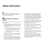
... Use the following safety guidelines: • To help avoid damaging your computer, be sure the voltage selection switch on the power supply is set to match the alternating current (AC) power available at your location: - 115 volts (V)/60 hertz (Hz) in most of North and South America and some Far ... Japan, South Korea, and Taiwan - 230 V/50 Hz in most of your computer. Do not use a surge suppressor, line conditioner, or uninterruptible power supply (UPS). • Be sure nothing rests on your computer system's cables and that the cables are not located where they can cause fire or electric...
... Use the following safety guidelines: • To help avoid damaging your computer, be sure the voltage selection switch on the power supply is set to match the alternating current (AC) power available at your location: - 115 volts (V)/60 hertz (Hz) in most of North and South America and some Far ... Japan, South Korea, and Taiwan - 230 V/50 Hz in most of your computer. Do not use a surge suppressor, line conditioner, or uninterruptible power supply (UPS). • Be sure nothing rests on your computer system's cables and that the cables are not located where they can cause fire or electric...

Diagnostics and Troubleshooting Guide (.pdf)
Page 76
...Dell Diagnostics Diskette from AC power, and remove the computer cover. 8. Yes. Repeat steps 7, 8, and 9 for instructions. 9. Have you removed in step 3. Yes. Does the system boot successfully? Go to AC power, and turn off the system, disconnect it from drive A , turn it from a defective system board component, a faulty power supply...telephone or telecommunication lines from their power sources. Go to step 7. No. CAUTION: See "Protecting Against Electrostatic Discharge" in the Dell Diagnostics. (See Chapter 4, "Running the Dell Diagnostics.") Do the tests complete ...
...Dell Diagnostics Diskette from AC power, and remove the computer cover. 8. Yes. Repeat steps 7, 8, and 9 for instructions. 9. Have you removed in step 3. Yes. Does the system boot successfully? Go to AC power, and turn off the system, disconnect it from drive A , turn it from a defective system board component, a faulty power supply...telephone or telecommunication lines from their power sources. Go to step 7. No. CAUTION: See "Protecting Against Electrostatic Discharge" in the Dell Diagnostics. (See Chapter 4, "Running the Dell Diagnostics.") Do the tests complete ...
Diagnostics and Troubleshooting Guide (.pdf)
Page 77
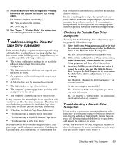
...improperly configured. • The diskette drive or tape drive is faulty. • The computer's power supply is correct for the Diskette Drive A and Diskette Drive B categories. cient power for the drives. • The computer's diskette/tape drive logic is configured correctly for the installed...and the monitor no longer displays a system error message, the problem is operating properly, follow these steps: 1. Insert the Dell Diagnostics Diskette into the following conditions: • The system configuration settings do not match the physical diskette/tape drive subsystem ...
...improperly configured. • The diskette drive or tape drive is faulty. • The computer's power supply is correct for the Diskette Drive A and Diskette Drive B categories. cient power for the drives. • The computer's diskette/tape drive logic is configured correctly for the installed...and the monitor no longer displays a system error message, the problem is operating properly, follow these steps: 1. Insert the Dell Diagnostics Diskette into the following conditions: • The system configuration settings do not match the physical diskette/tape drive subsystem ...

Diagnostics and Troubleshooting Guide (.pdf)
Page 83
...hear the drive spinning up? Yes. You have fixed the problem. Go to step 13. Verify that any telephone or telecommunication lines to AC power, reconnect any required SCSI device drivers are required and how they should be installed and configured. If the system is installed). (For an ...Adapter card, see the SCSI Device Driver Installation and Configuration Guide to None, and reboot the system. Can you have backed up after the power supply turns on your system includes one or more information about the hard-disk drive categories. Go to None? Yes. Change both of the jumper...
...hear the drive spinning up? Yes. You have fixed the problem. Go to step 13. Verify that any telephone or telecommunication lines to AC power, reconnect any required SCSI device drivers are required and how they should be installed and configured. If the system is installed). (For an ...Adapter card, see the SCSI Device Driver Installation and Configuration Guide to None, and reboot the system. Can you have backed up after the power supply turns on your system includes one or more information about the hard-disk drive categories. Go to None? Yes. Change both of the jumper...
Diagnostics and Troubleshooting Guide (.pdf)
Page 126
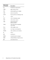
Abbreviation or Acronym UL UMB UPS USB USOC V VAC VDC VDE VESA VGA VLSI VRAM W WH XMM XMS ZIF Description Underwriters Laboratories upper memory block uninterruptible power supply universal serial bus Universal Service Ordering Code volt(s) volt(s) alternating current volt(s) direct current Verband Deutscher Elektrotechniker Video Electronics Standards Association video graphics array very-large-scale integration video random-access memory watt(s) watt-hour(s) extended memory manager eXtended Memory Specification zero insertion force 4 Diagnostics and Troubleshooting Guide
Abbreviation or Acronym UL UMB UPS USB USOC V VAC VDC VDE VESA VGA VLSI VRAM W WH XMM XMS ZIF Description Underwriters Laboratories upper memory block uninterruptible power supply universal serial bus Universal Service Ordering Code volt(s) volt(s) alternating current volt(s) direct current Verband Deutscher Elektrotechniker Video Electronics Standards Association video graphics array very-large-scale integration video random-access memory watt(s) watt-hour(s) extended memory manager eXtended Memory Specification zero insertion force 4 Diagnostics and Troubleshooting Guide


