Service Manual
Page 9
...the system clock frequency. System Overview 1-1 These Dell systems incorporate the high-performance PCI local bus as well as follows: • Dell OptiPlex GXpro 180 systems - 180 MHz derived from a system clock frequency of 60 MHz • Dell OptiPlex GXpro 200 systems - 200 MHz derived from a ...system clock frequency of 66 MHz Dell OptiPlex GXpro systems contain either an integrated 10-Mbps or...
...the system clock frequency. System Overview 1-1 These Dell systems incorporate the high-performance PCI local bus as well as follows: • Dell OptiPlex GXpro 180 systems - 180 MHz derived from a system clock frequency of 60 MHz • Dell OptiPlex GXpro 200 systems - 200 MHz derived from a ...system clock frequency of 66 MHz Dell OptiPlex GXpro systems contain either an integrated 10-Mbps or...
Service Manual
Page 10
For a complete list of system features, see "Technical Specifications" found in a traditional personal computer, the Dell OptiPlex GXpro desktop systems include the following the text in this manual, assume that provide ECC functionality when used with two USB-compliant connectors (included on systems ...-Based Diagnostics" in Chapter 2). All of high-speed EDO DIMMs that the location or direction relative to the system unit is as shown in Figure 1-1. 1-2 Dell OptiPlex GXpro Systems Service Manual System Features In addition to the standard features found later in this chapter.
For a complete list of system features, see "Technical Specifications" found in a traditional personal computer, the Dell OptiPlex GXpro desktop systems include the following the text in this manual, assume that provide ECC functionality when used with two USB-compliant connectors (included on systems ...-Based Diagnostics" in Chapter 2). All of high-speed EDO DIMMs that the location or direction relative to the system unit is as shown in Figure 1-1. 1-2 Dell OptiPlex GXpro Systems Service Manual System Features In addition to the standard features found later in this chapter.
Service Manual
Page 12
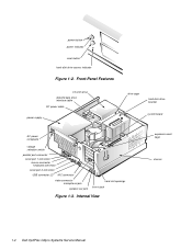
... card-slot openings line-in jack Figure 1-3. power button power indicator reset button hard-disk drive access indicator Figure 1-2. Internal View expansion-card cage chassis 1-4 Dell OptiPlex GXpro Systems Service Manual
... card-slot openings line-in jack Figure 1-3. power button power indicator reset button hard-disk drive access indicator Figure 1-2. Internal View expansion-card cage chassis 1-4 Dell OptiPlex GXpro Systems Service Manual
Service Manual
Page 14
... as opposed to the 8-MHz operating frequency of which can contain up to two high- NOTE: Some users may use an ISA video adapter card. 1-6 Dell OptiPlex GXpro Systems Service Manual Hard-Disk Drive Options The hard-disk drive bracket is much faster.
... as opposed to the 8-MHz operating frequency of which can contain up to two high- NOTE: Some users may use an ISA video adapter card. 1-6 Dell OptiPlex GXpro Systems Service Manual Hard-Disk Drive Options The hard-disk drive bracket is much faster.
Service Manual
Page 16
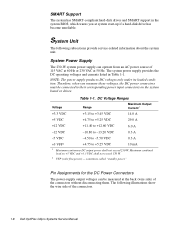
... provide service-related information about the system unit. Table 1-1. sometimes called "standby power." . System Unit The following illustrations show the wire side of the connectors. 1-8 Dell OptiPlex GXpro Systems Service Manual NOTE: The power supply produces DC voltages only under its loaded condition. Therefore, when you at the back (wire side) of the...
... provide service-related information about the system unit. Table 1-1. sometimes called "standby power." . System Unit The following illustrations show the wire side of the connectors. 1-8 Dell OptiPlex GXpro Systems Service Manual NOTE: The power supply produces DC voltages only under its loaded condition. Therefore, when you at the back (wire side) of the...
Service Manual
Page 18
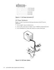
DC Power Connector P7 DC Power Distribution Figures 1-8 and 1-9 provide the following information about DC power distribution: • Power-supply connector identification • Power cable connections for diskette, tape, CD-ROM, and hard-disk drives • Power distribution to sockets and connectors on the system board P4 P6 P5 P3 P1 P7 P2 Figure 1-8. DC Power Cables 1-10 Dell OptiPlex GXpro Systems Service Manual P7 1 2 34 5 6 +3.3 VDC (blue/white) +3.3 VDC (blue/white) +3.3 VDC (blue/white) common (black) common (black) common (black) Figure 1-7.
DC Power Connector P7 DC Power Distribution Figures 1-8 and 1-9 provide the following information about DC power distribution: • Power-supply connector identification • Power cable connections for diskette, tape, CD-ROM, and hard-disk drives • Power distribution to sockets and connectors on the system board P4 P6 P5 P3 P1 P7 P2 Figure 1-8. DC Power Cables 1-10 Dell OptiPlex GXpro Systems Service Manual P7 1 2 34 5 6 +3.3 VDC (blue/white) +3.3 VDC (blue/white) +3.3 VDC (blue/white) common (black) common (black) common (black) Figure 1-7.
Service Manual
Page 20
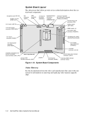
... power connector (RSR PWR1) System Board Layout The subsections that came with your system for information on removing and replacing video-memory upgrade chips. 1-12 Dell OptiPlex GXpro Systems Service Manual NIC connector (ENET) USB connector (USB) serial port 2 connector (SERIAL2) keyboard/mouse connectors (stacked) (KYBD/MOUSE) serial port 1/parallel port connectors (stacked...
... power connector (RSR PWR1) System Board Layout The subsections that came with your system for information on removing and replacing video-memory upgrade chips. 1-12 Dell OptiPlex GXpro Systems Service Manual NIC connector (ENET) USB connector (USB) serial port 2 connector (SERIAL2) keyboard/mouse connectors (stacked) (KYBD/MOUSE) serial port 1/parallel port connectors (stacked...
Service Manual
Page 22
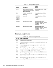
.... Not installed (reserved, do not change ) Reserved. Interrupt Assignments IRQ Line Used By/Available IRQ0 Generated by interrupt controller to parallel port requires service. 1-14 Dell OptiPlex GXpro Systems Service Manual IRQ4 for use by super I /O controller to corresponding serial port requires service (IRQ3 for internal...
.... Not installed (reserved, do not change ) Reserved. Interrupt Assignments IRQ Line Used By/Available IRQ0 Generated by interrupt controller to parallel port requires service. 1-14 Dell OptiPlex GXpro Systems Service Manual IRQ4 for use by super I /O controller to corresponding serial port requires service (IRQ3 for internal...
Service Manual
Page 24
... expansion-card connector data width (maximum 16 bits PCI expansion-card connector size 120 pins PCI expansion-card connector data width (maximum 32 bits 1-16 Dell OptiPlex GXpro Systems Service Manual
... expansion-card connector data width (maximum 16 bits PCI expansion-card connector size 120 pins PCI expansion-card connector data width (maximum 32 bits 1-16 Dell OptiPlex GXpro Systems Service Manual
Service Manual
Page 26
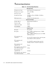
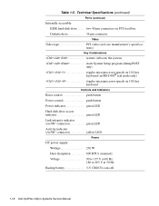
Technical Specifications (continued) Ports (continued) Internally accessible: EIDE hard-disk drive . . . . Table 1-5. two 40-pin connectors on PCI local bus Diskette drive 34-pin connector Video Video type PCI video card (see manufacturer's specifications) Key Combinations
Technical Specifications (continued) Ports (continued) Internally accessible: EIDE hard-disk drive . . . . Table 1-5. two 40-pin connectors on PCI local bus Diskette drive 34-pin connector Video Video type PCI video card (see manufacturer's specifications) Key Combinations
Service Manual
Page 30
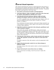
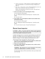
... the monitor. 7. While performing the visual inspection, make any peripherals, and cables. If one of the system unit as well as to replace the keyboard. 2-2 Dell OptiPlex GXpro Systems Service Manual For proper connection of the interface cable must be secure enough to the serial ports, parallel port, and USB are identical except...
... the monitor. 7. While performing the visual inspection, make any peripherals, and cables. If one of the system unit as well as to replace the keyboard. 2-2 Dell OptiPlex GXpro Systems Service Manual For proper connection of the interface cable must be secure enough to the serial ports, parallel port, and USB are identical except...
Service Manual
Page 32
... if possible. vide status information. Yes. See "Running the Diskette-Based Diagnostics" found later in their sockets, press firmly on the top of each chip. 2-4 Dell OptiPlex GXpro Systems Service Manual Proceed to locate components in this section, ensure that all open files and exited all chips, DIMMs, and expansion cards, are fully...
... if possible. vide status information. Yes. See "Running the Diskette-Based Diagnostics" found later in their sockets, press firmly on the top of each chip. 2-4 Dell OptiPlex GXpro Systems Service Manual Proceed to locate components in this section, ensure that all open files and exited all chips, DIMMs, and expansion cards, are fully...
Service Manual
Page 34
If no errors are found in the Diagnostics and Troubleshooting Guide. 2-6 Dell OptiPlex GXpro Systems Service Manual Tests a particular area or subsystem Getting Help If none of the troubleshooting procedures in this chapter or the tests in the diskette-... Specific Tests - For instructions, see the chapter titled "Getting Help" in RAM, the diagnostics loads and the Diagnostics Menu appears. Starting the diagnostics causes the Dell logo screen to isolate a failure • Run All Tests - If a RAM error is detected, a message appears on the monitor screen, followed by a message indicating ...
If no errors are found in the Diagnostics and Troubleshooting Guide. 2-6 Dell OptiPlex GXpro Systems Service Manual Tests a particular area or subsystem Getting Help If none of the troubleshooting procedures in this chapter or the tests in the diskette-... Specific Tests - For instructions, see the chapter titled "Getting Help" in RAM, the diagnostics loads and the Diagnostics Menu appears. Starting the diagnostics causes the Dell logo screen to isolate a failure • Run All Tests - If a RAM error is detected, a message appears on the monitor screen, followed by a message indicating ...
Service Manual
Page 36
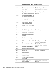
... timer tick Defective system board 4-2-2 Shutdown failure 4-2-3 Gate A20 failure 4-2-4 4-3-1 Unexpected interrupt in protected mode Memory failure above address 0FFFFh Faulty or improperly seated DIMMs 3-2 Dell OptiPlex GXpro Systems Service Manual Table 3-1. POST Beep Codes (continued) Beep Code Error Probable Causes 1-3-1 Main-memory refresh verifi-
... timer tick Defective system board 4-2-2 Shutdown failure 4-2-3 Gate A20 failure 4-2-4 4-3-1 Unexpected interrupt in protected mode Memory failure above address 0FFFFh Faulty or improperly seated DIMMs 3-2 Dell OptiPlex GXpro Systems Service Manual Table 3-1. POST Beep Codes (continued) Beep Code Error Probable Causes 1-3-1 Main-memory refresh verifi-
Service Manual
Page 38
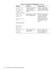
.... Faulty or improperly inserted diskette, incorrect settings in pathname specified. Faulty diskette, faulty or improperly connected diskette/tape drive interface cable, or loose power cable. 3-4 Dell OptiPlex GXpro Systems Service Manual System Error Messages Message Definition Probable Causes Address mark not found faulty disk sector or could not locate specific sector or track...
.... Faulty or improperly inserted diskette, incorrect settings in pathname specified. Faulty diskette, faulty or improperly connected diskette/tape drive interface cable, or loose power cable. 3-4 Dell OptiPlex GXpro Systems Service Manual System Error Messages Message Definition Probable Causes Address mark not found faulty disk sector or could not locate specific sector or track...
Service Manual
Page 40
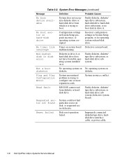
... failure System cannot communicate with keyboard. Table 3-2. Keyboard stuck key failure Keyboard controller failure Keyboard/mouse controller failed. Defective keyboard/ mouse controller (defective system board). 3-6 Dell OptiPlex GXpro Systems Service Manual System Error Messages (continued) Message Definition Probable Causes Invalid configuration information please run SETUP program System Setup program contains incorrect system configuration...
... failure System cannot communicate with keyboard. Table 3-2. Keyboard stuck key failure Keyboard controller failure Keyboard/mouse controller failed. Defective keyboard/ mouse controller (defective system board). 3-6 Dell OptiPlex GXpro Systems Service Manual System Error Messages (continued) Message Definition Probable Causes Invalid configuration information please run SETUP program System Setup program contains incorrect system configuration...
Service Manual
Page 42
... diskette, diskette/ tape drive subsystem, or hard-disk drive subsystem (defective system board). Improperly connected diskette/tape drive, harddisk drive interface cable, or power cable. 3-8 Dell OptiPlex GXpro Systems Service Manual Incorrect configuration settings in System Setup program incorrect, or operating system corrupted. Not a boot diskette No operating system on No operating system...
... diskette, diskette/ tape drive subsystem, or hard-disk drive subsystem (defective system board). Improperly connected diskette/tape drive, harddisk drive interface cable, or power cable. 3-8 Dell OptiPlex GXpro Systems Service Manual Incorrect configuration settings in System Setup program incorrect, or operating system corrupted. Not a boot diskette No operating system on No operating system...

Service Manual
Page 44
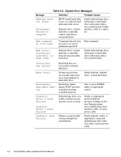
Table 3-2. System Error Messages (continued) Message Definition Probable Causes WarningTemperature is too high At system start-up, BIOS detected that one or both microprocessors are too hot. Write fault Write fault on selected drive MS-DOS cannot write to diskette or hard-disk drive. One or both microprocessors have overheated. Faulty diskette or harddisk drive. 3-10 Dell OptiPlex GXpro Systems Service Manual
Table 3-2. System Error Messages (continued) Message Definition Probable Causes WarningTemperature is too high At system start-up, BIOS detected that one or both microprocessors are too hot. Write fault Write fault on selected drive MS-DOS cannot write to diskette or hard-disk drive. One or both microprocessors have overheated. Faulty diskette or harddisk drive. 3-10 Dell OptiPlex GXpro Systems Service Manual

Service Manual
Page 46
... the computer, perform the following warning for personal injury or shock. 3. Wear a wrist grounding strap, and clip it to reduce the potential for your body. 4-2 Dell OptiPlex GXpro Systems Service Manual WARNING FOR YOUR PERSONAL SAFETY AND PROTECTION OF THE EQUIPMENT: Before you perform any static charge from your personal safety and to...
... the computer, perform the following warning for personal injury or shock. 3. Wear a wrist grounding strap, and clip it to reduce the potential for your body. 4-2 Dell OptiPlex GXpro Systems Service Manual WARNING FOR YOUR PERSONAL SAFETY AND PROTECTION OF THE EQUIPMENT: Before you perform any static charge from your personal safety and to...

Service Manual
Page 48
... installed. Padlock Removal 2. Before you reinstall the cover, fold all cables out of system unit Figure 4-3. Four plastic hooks on the inside the system unit. 4-4 Dell OptiPlex GXpro Systems Service Manual Lift the cover, from the back, pivoting it to swing up. 3. back of the way so that they do not interfere with...
... installed. Padlock Removal 2. Before you reinstall the cover, fold all cables out of system unit Figure 4-3. Four plastic hooks on the inside the system unit. 4-4 Dell OptiPlex GXpro Systems Service Manual Lift the cover, from the back, pivoting it to swing up. 3. back of the way so that they do not interfere with...


