Service Manual
Page 4
...Board 1-17 System Board Jumpers 1-18 Interrupt Assignments 1-19 DMA Channel Assignments 1-20 Hard-Disk Drive Service Information 1-20 Hard-Disk Drive for the Low-Profile Computer 1-21 Hard-Disk Drive for the Midsize Computer 1-21 Hard-Disk Drive for the Mini Tower Computer 1-22 Hard-Disk Drive for the OptiPlex...the System Diagnostics 2-6 Server-Based Diagnostics 2-6 Hard-Disk-Based Diagnostics (OptiPlex NX1 Systems Only 2-7 Diskette-Based Diagnostics 2-9 Connecting an External Diskette Drive to the OptiPlex NX1 Computer 2-9 Running the Diskette-Based Diagnostics 2-10 Getting Help ...
...Board 1-17 System Board Jumpers 1-18 Interrupt Assignments 1-19 DMA Channel Assignments 1-20 Hard-Disk Drive Service Information 1-20 Hard-Disk Drive for the Low-Profile Computer 1-21 Hard-Disk Drive for the Midsize Computer 1-21 Hard-Disk Drive for the Mini Tower Computer 1-22 Hard-Disk Drive for the OptiPlex...the System Diagnostics 2-6 Server-Based Diagnostics 2-6 Hard-Disk-Based Diagnostics (OptiPlex NX1 Systems Only 2-7 Diskette-Based Diagnostics 2-9 Connecting an External Diskette Drive to the OptiPlex NX1 Computer 2-9 Running the Diskette-Based Diagnostics 2-10 Getting Help ...

Service Manual
Page 5
...-Inch Drive Assembly 4-9 Hard-Disk Drive Assembly 4-10 System Power Supply 4-11 Expansion Cards 4-12 Expansion-Card Cage 4-12 Expansion Card 4-13 Riser Board 4-14 System Board 4-15 System Board Components 4-16 DIMMs 4-17 Video Memory 4-18 Microprocessor 4-19 SEC Cartridge/Heat Sink Assembly 4-19 System Battery 4-20 Recommended Tools 5-1 Precautionary Measures 5-1 Inside...
...-Inch Drive Assembly 4-9 Hard-Disk Drive Assembly 4-10 System Power Supply 4-11 Expansion Cards 4-12 Expansion-Card Cage 4-12 Expansion Card 4-13 Riser Board 4-14 System Board 4-15 System Board Components 4-16 DIMMs 4-17 Video Memory 4-18 Microprocessor 4-19 SEC Cartridge/Heat Sink Assembly 4-19 System Battery 4-20 Recommended Tools 5-1 Precautionary Measures 5-1 Inside...

Service Manual
Page 6
...-Disk Drive Bracket 5-12 Hard-Disk Drive 5-13 System Power Supply 5-14 Expansion Cards 5-15 Expansion-Card Cage 5-15 Expansion Card 5-16 Riser Board 5-17 System Board 5-18 System Board Components 5-19 DIMMs 5-20 Video Memory 5-21 Microprocessor 5-22 SEC Cartridge/Heat Sink Assembly 5-22 System Battery 5-23 Recommended Tools 6-1 Precautionary Measures 6-1 Inside... 6-12 Hard-Disk Drive Bracket 6-14 Hard-Disk Drive 6-15 System Power Supply 6-16 Expansion Cards 6-17 Expansion-Card Cage 6-17 Expansion Card 6-18 Riser Board 6-19 System Board 6-20 viii
...-Disk Drive Bracket 5-12 Hard-Disk Drive 5-13 System Power Supply 5-14 Expansion Cards 5-15 Expansion-Card Cage 5-15 Expansion Card 5-16 Riser Board 5-17 System Board 5-18 System Board Components 5-19 DIMMs 5-20 Video Memory 5-21 Microprocessor 5-22 SEC Cartridge/Heat Sink Assembly 5-22 System Battery 5-23 Recommended Tools 6-1 Precautionary Measures 6-1 Inside... 6-12 Hard-Disk Drive Bracket 6-14 Hard-Disk Drive 6-15 System Power Supply 6-16 Expansion Cards 6-17 Expansion-Card Cage 6-17 Expansion Card 6-18 Riser Board 6-19 System Board 6-20 viii

Service Manual
Page 7
... 1-9 Internal View of the Midsize Chassis 1-10 Internal View of the Mini Tower Chassis 1-11 Internal View of the OptiPlex NX1 Chassis 1-12 Riser Board for the OptiPlex NX1 Computer 1-13 ix Figure 1-2. System Board Components 6-21 DIMMs 6-22 Video Memory 6-23 Microprocessor 6-24 SEC Cartridge/Heat Sink Assembly 6-24 System Battery 6-25 Recommended...
... 1-9 Internal View of the Midsize Chassis 1-10 Internal View of the Mini Tower Chassis 1-11 Internal View of the OptiPlex NX1 Chassis 1-12 Riser Board for the OptiPlex NX1 Computer 1-13 ix Figure 1-2. System Board Components 6-21 DIMMs 6-22 Video Memory 6-23 Microprocessor 6-24 SEC Cartridge/Heat Sink Assembly 6-24 System Battery 6-25 Recommended...
Service Manual
Page 8
...-Disk Drive Assembly Removal 4-10 System Power-Supply Removal 4-11 Expansion-Card Cage Removal 4-12 Expansion-Card Removal 4-13 Riser Board Removal 4-14 System Board Removal 4-15 System Board Components 4-16 x Figure 1-8. Figure 4-8. P3, P4, P5, P6, and P9 (All OptiPlex GX1 Chassis 1-24 DC Power Connectors P2 (Low-Profile Chassis) and P7 (All...
...-Disk Drive Assembly Removal 4-10 System Power-Supply Removal 4-11 Expansion-Card Cage Removal 4-12 Expansion-Card Removal 4-13 Riser Board Removal 4-14 System Board Removal 4-15 System Board Components 4-16 x Figure 1-8. Figure 4-8. P3, P4, P5, P6, and P9 (All OptiPlex GX1 Chassis 1-24 DC Power Connectors P2 (Low-Profile Chassis) and P7 (All...
Service Manual
Page 9
... Removal 5-12 Hard-Disk Drive Removal 5-13 System Power-Supply Removal 5-14 Expansion-Card Cage Removal 5-15 Expansion-Card Removal 5-16 Riser Board Removal 5-17 System Board Removal 5-18 System Board Components 5-19 DIMM Removal 5-20 DIMM Installation 5-20 Installing a Video-Memory Upgrade Module 5-21 SEC Cartridge/Heat Sink Removal 5-22 System Battery...
... Removal 5-12 Hard-Disk Drive Removal 5-13 System Power-Supply Removal 5-14 Expansion-Card Cage Removal 5-15 Expansion-Card Removal 5-16 Riser Board Removal 5-17 System Board Removal 5-18 System Board Components 5-19 DIMM Removal 5-20 DIMM Installation 5-20 Installing a Video-Memory Upgrade Module 5-21 SEC Cartridge/Heat Sink Removal 5-22 System Battery...
Service Manual
Page 10
... Setup Screens A-2 Sample Device List Screen A-8 Table 1-1. Figure 6-23. Figure 7-15. Table 1-3. Table 3-1. Figure 6-19. Figure 7-8. System-Board Jumper Descriptions 1-18 Interrupt Assignments 1-19 DREQ Line Assignments 1-20 OptiPlex GX1 DC Voltage Ranges 1-22 OptiPlex NX1 DC Voltage Ranges 1-30 Technical Specifications 1-33 POST Beep Codes 3-1 System Error Messages 3-3 System Setup Categories A-4 xii...
... Setup Screens A-2 Sample Device List Screen A-8 Table 1-1. Figure 6-23. Figure 7-15. Table 1-3. Table 3-1. Figure 6-19. Figure 7-8. System-Board Jumper Descriptions 1-18 Interrupt Assignments 1-19 DREQ Line Assignments 1-20 OptiPlex GX1 DC Voltage Ranges 1-22 OptiPlex NX1 DC Voltage Ranges 1-30 Technical Specifications 1-33 POST Beep Codes 3-1 System Error Messages 3-3 System Setup Categories A-4 xii...

Service Manual
Page 13
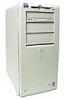
...tower (see Figure 1-1). System Overview 1-1 This manual contains field-servicing information for the Dell® OptiPlex® GX1 Managed PC and OptiPlex NX1 Net PC family of the OptiPlex GX1 and OptiPlex NX1 families; Chapters 4, 5, 6, and 7 are high-speed (266-, 333-, ...OptiPlex GX1 systems are available in the OptiPlex NX1 chassis (see Figure 1-1). The Dell OptiPlex GX1 and OptiPlex NX1 systems are chassis-specific. Chapters 1 through 3 and Appendix A contain information that applies to all models of computers. The OptiPlex GX1 and NX1 systems use a standard system board...
...tower (see Figure 1-1). System Overview 1-1 This manual contains field-servicing information for the Dell® OptiPlex® GX1 Managed PC and OptiPlex NX1 Net PC family of the OptiPlex GX1 and OptiPlex NX1 families; Chapters 4, 5, 6, and 7 are high-speed (266-, 333-, ...OptiPlex GX1 systems are available in the OptiPlex NX1 chassis (see Figure 1-1). The Dell OptiPlex GX1 and OptiPlex NX1 systems are chassis-specific. Chapters 1 through 3 and Appendix A contain information that applies to all models of computers. The OptiPlex GX1 and NX1 systems use a standard system board...

Service Manual
Page 15
...Dell Computer Corporation for improved operating speeds and overall performance. For additional performance, the OptiPlex GX1 and OptiPlex NX1 systems employ a secondary cache memory subsystem with a cache memory controller and 512 KB of 384 MB. Main memory for high performance in the following similarities: The same system board. However, the OptiPlex...), which permits processing data elements in the OptiPlex GX1 and OptiPlex NX1 computer families incorporate the Pentium II microprocessor for information about Dell-supported microprocessor upgrades. All four chassis configurations ...
...Dell Computer Corporation for improved operating speeds and overall performance. For additional performance, the OptiPlex GX1 and OptiPlex NX1 systems employ a secondary cache memory subsystem with a cache memory controller and 512 KB of 384 MB. Main memory for high performance in the following similarities: The same system board. However, the OptiPlex...), which permits processing data elements in the OptiPlex GX1 and OptiPlex NX1 computer families incorporate the Pentium II microprocessor for information about Dell-supported microprocessor upgrades. All four chassis configurations ...

Service Manual
Page 16
... in flash ROM, which allows for easy BIOS upgrades using diskette files or files downloaded from Dell's home page on the system board. The EIDE subsystem implemented on the system board provides two Mode-4, DMA bus-mastered EIDE interfaces, each time the system is started. The ... accessible drive bays at system start-up to the primary EIDE interface. As a standard feature, OptiPlex GX1 and OptiPlex NX1 systems are equipped with SMART technology. The OptiPlex GX1 and OptiPlex NX1 systems are equipped with Self-Monitoring and Analysis Reporting Technology (SMART), which warns you use hard...
... in flash ROM, which allows for easy BIOS upgrades using diskette files or files downloaded from Dell's home page on the system board. The EIDE subsystem implemented on the system board provides two Mode-4, DMA bus-mastered EIDE interfaces, each time the system is started. The ... accessible drive bays at system start-up to the primary EIDE interface. As a standard feature, OptiPlex GX1 and OptiPlex NX1 systems are equipped with SMART technology. The OptiPlex GX1 and OptiPlex NX1 systems are equipped with Self-Monitoring and Analysis Reporting Technology (SMART), which warns you use hard...

Service Manual
Page 17
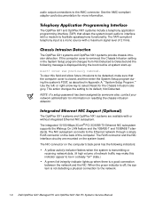
... The 40-pin AMC connector, shown in this computer requires an external diskette-drive kit as described in and microphone input. The OptiPlex NX1 system contains an integrated controller and diskette drive connector but is 1600 x 1200 with a diskette drive. The maximum supported resolution... controller, and an inter-integrated circuit (I2C)-compatible serial control port for interconnection of the video stream data transfers occur on the system board, which drives an external SVGA monitor. The ATI multimedia channel (AMC) implements a local graphics bus that connects to 8 MB via ...
... The 40-pin AMC connector, shown in this computer requires an external diskette-drive kit as described in and microphone input. The OptiPlex NX1 system contains an integrated controller and diskette drive connector but is 1600 x 1200 with a diskette drive. The maximum supported resolution... controller, and an inter-integrated circuit (I2C)-compatible serial control port for interconnection of the video stream data transfers occur on the system board, which drives an external SVGA monitor. The ATI multimedia channel (AMC) implements a local graphics bus that connects to 8 MB via ...
Service Manual
Page 18
...indicator is off, the system is a mono source with a modem to interface with a maximum signal level of the computer. The OptiPlex GX1 and OptiPlex NX1 systems include a telephony application programming interface (TAPI) that the computer cover is closed, and then enter the System Setup program ... state.) A green link integrity indicator lights up : To clear this indicator appear to be detected, make sure that allows the system board audio to facilitate speakerphone functionality. The integrated 10/100-Mbps 3Com® PCI 3C905B-TX Ethernet NIC subsystem supports the Wakeup On LAN ...
...indicator is off, the system is a mono source with a modem to interface with a maximum signal level of the computer. The OptiPlex GX1 and OptiPlex NX1 systems include a telephony application programming interface (TAPI) that the computer cover is closed, and then enter the System Setup program ... state.) A green link integrity indicator lights up : To clear this indicator appear to be detected, make sure that allows the system board audio to facilitate speakerphone functionality. The integrated 10/100-Mbps 3Com® PCI 3C905B-TX Ethernet NIC subsystem supports the Wakeup On LAN ...

Service Manual
Page 23
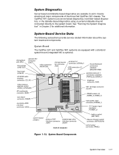
AC power receptacle security cable slot parallel port connector serial port 1 connector keyboard connector mouse connector USB connectors (2) serial port 2 connector video connector NIC connector (optional) audio connectors (3) padlock ring power supply external drive bays hard-disk drive bracket interface cable chassis intrusion switch expansion-card cage system board riser board System Overview 1-11
AC power receptacle security cable slot parallel port connector serial port 1 connector keyboard connector mouse connector USB connectors (2) serial port 2 connector video connector NIC connector (optional) audio connectors (3) padlock ring power supply external drive bays hard-disk drive bracket interface cable chassis intrusion switch expansion-card cage system board riser board System Overview 1-11

Service Manual
Page 25
...PCIto-PCI bridge. If the LED is applied to an installed PCI expansion card during system start-up. The riser board is not receiving power. The OptiPlex NX1 computer has one ISA expansion-card connector share a single expansion-card slot, resulting in a total of five ...see Figure 1-9). LED ISA2 connector HDLED connector P1 connector ISA1 connector PCI2 connector PCI1 connector The OptiPlex GX1 midsize computers have three expansion-card slots. The riser board has two ISA expansion-card connectors and two PCI expansion-card connectors. The computer automatically assigns ...
...PCIto-PCI bridge. If the LED is applied to an installed PCI expansion card during system start-up. The riser board is not receiving power. The OptiPlex NX1 computer has one ISA expansion-card connector share a single expansion-card slot, resulting in a total of five ...see Figure 1-9). LED ISA2 connector HDLED connector P1 connector ISA1 connector PCI2 connector PCI1 connector The OptiPlex GX1 midsize computers have three expansion-card slots. The riser board has two ISA expansion-card connectors and two PCI expansion-card connectors. The computer automatically assigns ...

Service Manual
Page 26
... connector ISA1 connector HDLED connector PCI5 connector PCI4 connector PCI3 connector P1 connector PCI2 connector PCI1 connector 1-14 if off, the riser board is receiving power; Both riser board options include the P1 connector (for connecting the NIC to -PCI bridge. If the LED is on, the riser... board is not receiving power. Two PCI/ISA expansion-card connector pairs each share an expansion-card slot, again resulting in a total of five expansion-card slots (see Figure 1-10). board, with a PCI-to the riser board cable) and an LED.
... connector ISA1 connector HDLED connector PCI5 connector PCI4 connector PCI3 connector P1 connector PCI2 connector PCI1 connector 1-14 if off, the riser board is receiving power; Both riser board options include the P1 connector (for connecting the NIC to -PCI bridge. If the LED is on, the riser... board is not receiving power. Two PCI/ISA expansion-card connector pairs each share an expansion-card slot, again resulting in a total of five expansion-card slots (see Figure 1-10). board, with a PCI-to the riser board cable) and an LED.

Service Manual
Page 27
...following subsections, and installation procedures are implemented in an SEC cartridge/heat sink assembly. On the OptiPlex GX1 and OptiPlex NX1 systems, the microprocessor and secondary L2 cache memory are provided for connecting the NIC to... a higher-performance microprocessor is receiving power; The mini tower riser board includes the P1 connector (for the various chassis configurations in a total of seven expansion-card slots (see Figure 1-11). if off, the riser board...
...following subsections, and installation procedures are implemented in an SEC cartridge/heat sink assembly. On the OptiPlex GX1 and OptiPlex NX1 systems, the microprocessor and secondary L2 cache memory are provided for connecting the NIC to... a higher-performance microprocessor is receiving power; The mini tower riser board includes the P1 connector (for the various chassis configurations in a total of seven expansion-card slots (see Figure 1-11). if off, the riser board...

Service Manual
Page 28
... board can upgrade video memory from 4 to 8 MB by a system administrator at a remote location: Perform computer setup processes Download and install software Perform file updates Perform asset-tracking functions Download and run the diagnostics over the network Dell OptiPlex ...See the online System User's Guide or Chapter 6, "Installing System Board Options," in the Dell Accessories folder) that provides additional hardware and software installation, configuration information, and Dell contact information. OptiPlex NX1 systems also contain an online Network Administrator's Guide. 1-16 Main...
... board can upgrade video memory from 4 to 8 MB by a system administrator at a remote location: Perform computer setup processes Download and install software Perform file updates Perform asset-tracking functions Download and run the diagnostics over the network Dell OptiPlex ...See the online System User's Guide or Chapter 6, "Installing System Board Options," in the Dell Accessories folder) that provides additional hardware and software installation, configuration information, and Dell contact information. OptiPlex NX1 systems also contain an online Network Administrator's Guide. 1-16 Main...
Service Manual
Page 29
...INTRUSION) control panel connector (PANEL) System Overview 1-17 The OptiPlex GX1 and OptiPlex NX1 systems are available to the system board. The following subsections provide service-related information about the system board and components. microphone jack (MIC) line-out jack (...input connector (POWER_1) 3.3-V power input connector (POWER_2) system board jumpers primary EIDE diskette/tape drive interface connector interface connector (IDE1) (DSKT) front of the three Dell OptiPlex GX1 chassis. The OptiPlex NX1 systems use server-based diagnostics, hard-disk-based diagnostics,...
...INTRUSION) control panel connector (PANEL) System Overview 1-17 The OptiPlex GX1 and OptiPlex NX1 systems are available to the system board. The following subsections provide service-related information about the system board and components. microphone jack (MIC) line-out jack (...input connector (POWER_1) 3.3-V power input connector (POWER_2) system board jumpers primary EIDE diskette/tape drive interface connector interface connector (IDE1) (DSKT) front of the three Dell OptiPlex GX1 chassis. The OptiPlex NX1 systems use server-based diagnostics, hard-disk-based diagnostics,...

Service Manual
Page 34
The hard-disk drive bracket can be connected to their corresponding power input connectors on the system board or drives. +3.3 VDC +3.15 to +3.45 VDC 12.0 A1 (low-profile computers); 14.0 A1 (midsize and mini tower computers) +5 VDC +4.75 to +5.25 VDC 18.0 ...
The hard-disk drive bracket can be connected to their corresponding power input connectors on the system board or drives. +3.3 VDC +3.15 to +3.45 VDC 12.0 A1 (low-profile computers); 14.0 A1 (midsize and mini tower computers) +5 VDC +4.75 to +5.25 VDC 18.0 ...
Service Manual
Page 36
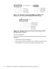
1234 P2, P3, P5, P6, P9 +5 VDC (red) common (black) common (black) +12 VDC (yellow) P4 12 34 +12 VDC (yellow) common (black) common (black) +5 VDC (red) P2, P7 1 2 34 5 6 +3.3 VDC (blue/white) +3.3 VDC (blue/white) +3.3 VDC (blue/white) common (black) common (black) common (black) Figures 1-18 through 1-22 provide the following information about DC power distribution: Power-supply connector identification Power cable connections for diskette, tape, CD-ROM, and hard-disk drives Power distribution to sockets and connectors on the system board 1-24
1234 P2, P3, P5, P6, P9 +5 VDC (red) common (black) common (black) +12 VDC (yellow) P4 12 34 +12 VDC (yellow) common (black) common (black) +5 VDC (red) P2, P7 1 2 34 5 6 +3.3 VDC (blue/white) +3.3 VDC (blue/white) +3.3 VDC (blue/white) common (black) common (black) common (black) Figures 1-18 through 1-22 provide the following information about DC power distribution: Power-supply connector identification Power cable connections for diskette, tape, CD-ROM, and hard-disk drives Power distribution to sockets and connectors on the system board 1-24

