User Guide
Page 26
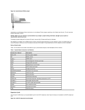
... step due to Contents Page Expansion Cards: Dell™ OptiPlex™ GX100 System User's Guide Overview Riser Boards Installing an Expansion Card Removing an Expansion Card Overview OptiPlex GX100 systems can accommodate a mix of 32-bit Peripheral Component Interconnect (PCI) expansion cards and, optionally, 16-bit and 8-bit Industry-Standard Architecture (ISA) expansion cards, depending on...
... step due to Contents Page Expansion Cards: Dell™ OptiPlex™ GX100 System User's Guide Overview Riser Boards Installing an Expansion Card Removing an Expansion Card Overview OptiPlex GX100 systems can accommodate a mix of 32-bit Peripheral Component Interconnect (PCI) expansion cards and, optionally, 16-bit and 8-bit Industry-Standard Architecture (ISA) expansion cards, depending on...
User Guide
Page 27
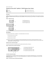
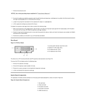
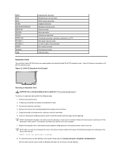
... Board (Standard) 1 Auxiliary power indicator (AUX_LED) 2 PCI expansion-card connector 5 (PCI5) 3 Remote Wakeup header (WOL) 4 PCI expansion-card connector 1 (PCI1) Figure 6. The PCI riser board provides five PCI expansion card slots. Mini Tower Chassis PCI/ISA Riser Board (Optional) 1 PCI expansion slot 1 (PCI1) 2 PCI expansion slot 2 (PCI2) 3 PCI expansion slot 3 (PCI3) 4 PCI expansion slot 4 (PCI4) 5 ISA expansion slot 1 (ISA1...
... Board (Standard) 1 Auxiliary power indicator (AUX_LED) 2 PCI expansion-card connector 5 (PCI5) 3 Remote Wakeup header (WOL) 4 PCI expansion-card connector 1 (PCI1) Figure 6. The PCI riser board provides five PCI expansion card slots. Mini Tower Chassis PCI/ISA Riser Board (Optional) 1 PCI expansion slot 1 (PCI1) 2 PCI expansion slot 2 (PCI2) 3 PCI expansion slot 3 (PCI3) 4 PCI expansion slot 4 (PCI4) 5 ISA expansion slot 1 (ISA1...
User Guide
Page 65
... Graphics Accelerator with PCI specification 2.2. l Full compliance with Dynamic Video Memory (DVM) technology architecture. l Embedded System Setup for networked environments. For additional hardware features, see "Technical Specifications." Back to Contents Page Introduction: Dell™ OptiPlex™ GX100 System User's Guide Overview Hardware Features Software Features Manageability Features ENERGY STAR® Compliance Overview Dell OptiPlex GX100 Managed PC...
... Graphics Accelerator with PCI specification 2.2. l Full compliance with Dynamic Video Memory (DVM) technology architecture. l Embedded System Setup for networked environments. For additional hardware features, see "Technical Specifications." Back to Contents Page Introduction: Dell™ OptiPlex™ GX100 System User's Guide Overview Hardware Features Software Features Manageability Features ENERGY STAR® Compliance Overview Dell OptiPlex GX100 Managed PC...
User Guide
Page 82
...back panel. Integrated NIC Connector Your system has an integrated 10/100-megabit-per-second (Mbps) 3Com® Peripheral Component Interconnect (PCI) 3C905C-TX Ethernet network interface controller (NIC). Port designations are used , for example, in software installation procedures to identify the ...and the NIC. Keyboard Connector The NIC includes a Remote Wake Up feature that require serial transmission (sending one bit of your Dell ResourceCD for instructions. When the green indicator is off the computer and any attached peripherals before connecting a mouse to the new ...
...back panel. Integrated NIC Connector Your system has an integrated 10/100-megabit-per-second (Mbps) 3Com® Peripheral Component Interconnect (PCI) 3C905C-TX Ethernet network interface controller (NIC). Port designations are used , for example, in software installation procedures to identify the ...and the NIC. Keyboard Connector The NIC includes a Remote Wake Up feature that require serial transmission (sending one bit of your Dell ResourceCD for instructions. When the green indicator is off the computer and any attached peripherals before connecting a mouse to the new ...
User Guide
Page 89
... AC power is restored. The following subsections describe typical boot devices. Diskette Drive A: Back to Contents Page System Setup Options: Dell™ OptiPlex™ GX100 System User's Guide AC Power Recovery Asset Tag Auto Power On Boot Sequence CPU ID CPU Speed Diskette Drive A and Diskette ...Drive B Integrated Devices Keyboard NumLock PCI IRQ Assignment Primary Drive n and Secondary Drive n Remote Wake Up Report Keyboard Errors System...
... AC power is restored. The following subsections describe typical boot devices. Diskette Drive A: Back to Contents Page System Setup Options: Dell™ OptiPlex™ GX100 System User's Guide AC Power Recovery Asset Tag Auto Power On Boot Sequence CPU ID CPU Speed Diskette Drive A and Diskette ...Drive B Integrated Devices Keyboard NumLock PCI IRQ Assignment Primary Drive n and Secondary Drive n Remote Wake Up Report Keyboard Errors System...

User Guide
Page 92
.... As part of keys on your system boots with the Num Lock mode activated on the system board; Set USB Emulation to PCI devices unless a particular device, device driver, or operating system requires a specific IRQ line already in an expansion slot. Video DAC.... Selecting Off disables the integrated EIDE interface. Diskette Interface Diskette Interface controls the operation of the keys. When Off is loaded by a PCI device. A change to the primary EIDE interface connector (labeled "IDE1") on 101- Primary Video Controller Primary Video Controller determines which IRQ ...
.... As part of keys on your system boots with the Num Lock mode activated on the system board; Set USB Emulation to PCI devices unless a particular device, device driver, or operating system requires a specific IRQ line already in an expansion slot. Video DAC.... Selecting Off disables the integrated EIDE interface. Diskette Interface Diskette Interface controls the operation of the keys. When Off is loaded by a PCI device. A change to the primary EIDE interface connector (labeled "IDE1") on 101- Primary Video Controller Primary Video Controller determines which IRQ ...
User Guide
Page 100
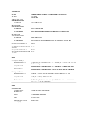
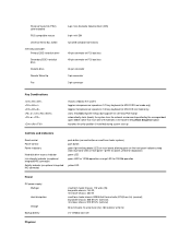
... bay for a removable media device one 3.5-inch bay for a 3.5-inch diskette drive; two shared PCI/ISA expansion slots PCI expansion-card connector size 120 pins PCI expansion-card connector data width 32 bits (maximum) ISA expansion-card connector size ISA expansion-card connector...-factor chassis expansion-card connectors: PCI riser board Peripheral Component Interconnect (PCI), Industry-Standard Architecture (ISA) PCI: 33 MHz ISA: 8.33 MHz two PCI expansion slots Low-profile chassis expansion-card connectors: PCI riser board three PCI expansion slots PCI/ISA riser board one 1.6-inch-...
... bay for a removable media device one 3.5-inch bay for a 3.5-inch diskette drive; two shared PCI/ISA expansion slots PCI expansion-card connector size 120 pins PCI expansion-card connector data width 32 bits (maximum) ISA expansion-card connector size ISA expansion-card connector...-factor chassis expansion-card connectors: PCI riser board Peripheral Component Interconnect (PCI), Industry-Standard Architecture (ISA) PCI: 33 MHz ISA: 8.33 MHz two PCI expansion slots Low-profile chassis expansion-card connectors: PCI riser board three PCI expansion slots PCI/ISA riser board one 1.6-inch-...
User Guide
Page 101
... drive Remote Wake Up Fan 6-pin mini-Deutsche Industrie Norm (DIN) 6-pin mini-DIN two USB-compliant connectors 40-pin connector on PCI local bus 40-pin connector on PCI local bus 34-pin connector 3-pin connector 3-pin connector Key Combinations or or restarts (reboots) the system toggles microprocessor speeds on 101...
... drive Remote Wake Up Fan 6-pin mini-Deutsche Industrie Norm (DIN) 6-pin mini-DIN two USB-compliant connectors 40-pin connector on PCI local bus 40-pin connector on PCI local bus 34-pin connector 3-pin connector 3-pin connector Key Combinations or or restarts (reboots) the system toggles microprocessor speeds on 101...
Service Manual
Page 10
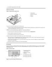
... Rotate the lever upward until it stops in the upright position, align the expansion-card cage slots with either a PCI riser board (see Figure 15) or a PCI/ISA riser board (see Figure 16). Slide the expansion-card cage into the low-profile chassis, perform the following ... securing lever in an upright position. 3. To replace the expansion-card cage into place. 2. Figure 15. Low-Profile Chassis PCI/ISA Riser Board The PCI riser board provides three PCI expansion card slots. Expansion-Card Cage Removal 1 Securing lever 2 Expansion-card cage 3 Slots (2) 4 Tabs (2) To remove...
... Rotate the lever upward until it stops in the upright position, align the expansion-card cage slots with either a PCI riser board (see Figure 15) or a PCI/ISA riser board (see Figure 16). Slide the expansion-card cage into the low-profile chassis, perform the following ... securing lever in an upright position. 3. To replace the expansion-card cage into place. 2. Figure 15. Low-Profile Chassis PCI/ISA Riser Board The PCI riser board provides three PCI expansion card slots. Expansion-Card Cage Removal 1 Securing lever 2 Expansion-card cage 3 Slots (2) 4 Tabs (2) To remove...
Service Manual
Page 11
... cage. Remove the expansion cards installed in the slots. 3. Layout of System Board Jumpers shared with PCI2) 3 ISA expansion slot 2 (ISA2) 4 Remote Wakeup header (WOL) 5 PCI expansion slot 1 (PCI1) 6 PCI expansion slot 2 (PCI2; shared with ISA1) To remove the riser board, perform the following steps.
... cage. Remove the expansion cards installed in the slots. 3. Layout of System Board Jumpers shared with PCI2) 3 ISA expansion slot 2 (ISA2) 4 Remote Wakeup header (WOL) 5 PCI expansion slot 1 (PCI1) 6 PCI expansion slot 2 (PCI2; shared with ISA1) To remove the riser board, perform the following steps.
Service Manual
Page 12
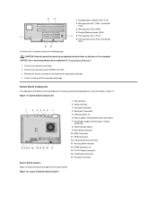
... power input connector 3.3-V power input connector Riser board connector Serial port connectors USB connectors Expansion Cards The low-profile GX100 chassis can accommodate three 32-bit PCI expansion cards. System Board Labels Table 1 lists the labels for this computer are disabled. Figure 19 shows an...remove it entirely, or carefully fit it gives a brief description of two or more pins on only one of a 32-bit PCI expansion card. Dell shipped your computer with a PSWD jumper installed, meaning that password features for connectors and sockets on your system or unpredictable results ...
... power input connector 3.3-V power input connector Riser board connector Serial port connectors USB connectors Expansion Cards The low-profile GX100 chassis can accommodate three 32-bit PCI expansion cards. System Board Labels Table 1 lists the labels for this computer are disabled. Figure 19 shows an...remove it entirely, or carefully fit it gives a brief description of two or more pins on only one of a 32-bit PCI expansion card. Dell shipped your computer with a PSWD jumper installed, meaning that password features for connectors and sockets on your system or unpredictable results ...

Service Manual
Page 31
... 21. Riser Boards The mini tower chassis is fully seated in an upright position. The PCI/ISA riser board provides three PCI expansion slots, two ISA expansion slots, and two shared PCI/ISA expansion slots. Slide the expansion-card cage out of the previous procedure. Reconnect any cables... that the riser board is available with either a PCI riser board (see Figure 22) or a PCI/ISA riser board (see Figure 22). 3. The PCI riser board provides five PCI expansion card slots. Locate the securing lever (see Figure 21). card cage (see...
... 21. Riser Boards The mini tower chassis is fully seated in an upright position. The PCI/ISA riser board provides three PCI expansion slots, two ISA expansion slots, and two shared PCI/ISA expansion slots. Slide the expansion-card cage out of the previous procedure. Reconnect any cables... that the riser board is available with either a PCI riser board (see Figure 22) or a PCI/ISA riser board (see Figure 22). 3. The PCI riser board provides five PCI expansion card slots. Locate the securing lever (see Figure 21). card cage (see...
Service Manual
Page 32
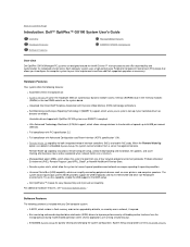
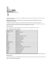
shared with PCI5) 10 PCI expansion slot 5 (PCI5; Remove the screws securing the riser board to the expansion-card cage. shared with PCI4) 6 Standby power indicator LED (AUX_LED) 7 ISA expansion ... expansion cards installed in Figure 24. Figure 24. shared with ISA1) 5 ISA expansion slot 1 (ISA1; CAUTION: Use a wrist grounding strap as explained in "Precautionary Measures." 1 PCI expansion slot 1 (PCI1) 2 PCI expansion slot 2 (PCI2) 3 PCI expansion slot 3 (PCI3) 4 PCI expansion slot 4 (PCI4; Remove the expansion-card cage. 2.
shared with PCI5) 10 PCI expansion slot 5 (PCI5; Remove the screws securing the riser board to the expansion-card cage. shared with PCI4) 6 Standby power indicator LED (AUX_LED) 7 ISA expansion ... expansion cards installed in Figure 24. Figure 24. shared with ISA1) 5 ISA expansion slot 1 (ISA1; CAUTION: Use a wrist grounding strap as explained in "Precautionary Measures." 1 PCI expansion slot 1 (PCI1) 2 PCI expansion slot 2 (PCI2) 3 PCI expansion slot 3 (PCI3) 4 PCI expansion slot 4 (PCI4; Remove the expansion-card cage. 2.
Service Manual
Page 33
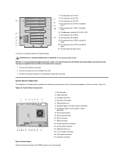
...indicated. NOTICE: Make sure your system or unpredictable results may occur. Otherwise, damage to five 32-bit PCI expansion cards. Dell shipped your system board and gives a brief description of a 32-bit PCI expansion card. When you remove the jumper, or when you change a jumper setting, pull the jumper ... Main power input connector 3.3-volt V power input connector Riser board connector Serial port connectors USB connectors Expansion Cards The mini tower GX100 chassis can accommodate up to your system is turned off its pin(s) and carefully fit it down over the pins. Figure 26. 32...
...indicated. NOTICE: Make sure your system or unpredictable results may occur. Otherwise, damage to five 32-bit PCI expansion cards. Dell shipped your system board and gives a brief description of a 32-bit PCI expansion card. When you remove the jumper, or when you change a jumper setting, pull the jumper ... Main power input connector 3.3-volt V power input connector Riser board connector Serial port connectors USB connectors Expansion Cards The mini tower GX100 chassis can accommodate up to your system is turned off its pin(s) and carefully fit it down over the pins. Figure 26. 32...
Service Manual
Page 51
...board off the expansion card cage. NOTICE: Use a wrist grounding strap as explained in the slots. 3. Riser Board Figure 19. To remove the PCI riser board, perform the following steps: 1. Remove the expansion cards installed in "Precautionary Measures." 2. System Board Components The subsections that will not ..., align the tabs in the RISER connector on the left side of the chassis wall (see Figure 19). Make sure that has two PCI expansion-card connectors (see Figure 18). Figure 20. Examine the cables connected to the expansion-card cage. 4. Remove the screws securing the...
...board off the expansion card cage. NOTICE: Use a wrist grounding strap as explained in the slots. 3. Riser Board Figure 19. To remove the PCI riser board, perform the following steps: 1. Remove the expansion cards installed in "Precautionary Measures." 2. System Board Components The subsections that will not ..., align the tabs in the RISER connector on the left side of the chassis wall (see Figure 19). Make sure that has two PCI expansion-card connectors (see Figure 18). Figure 20. Examine the cables connected to the expansion-card cage. 4. Remove the screws securing the...
Service Manual
Page 53
... EIDE interface connector Keyboard connector Microprocessor connector Video connector Mouse connector Control panel connector Parallel port connector; Figure 22. 32-Bit PCI Expansion Card Example Removing an Expansion Card CAUTION: Use a wrist grounding strap as LPT1 Main power input connector 3.3-volt (V) ...board connector Serial port connectors USB connectors Expansion Cards The small-form-factor GX100 chassis can accommodate up : ALERT! If necessary, disconnect any cables connected to two half-length 32-bit PCI expansion cards. Remove the screw on the mounting bracket of the system. ...
... EIDE interface connector Keyboard connector Microprocessor connector Video connector Mouse connector Control panel connector Parallel port connector; Figure 22. 32-Bit PCI Expansion Card Example Removing an Expansion Card CAUTION: Use a wrist grounding strap as LPT1 Main power input connector 3.3-volt (V) ...board connector Serial port connectors USB connectors Expansion Cards The small-form-factor GX100 chassis can accommodate up : ALERT! If necessary, disconnect any cables connected to two half-length 32-bit PCI expansion cards. Remove the screw on the mounting bracket of the system. ...


