User Guide
Page 5
... of its socket with a blunt, nonconductive object, such as : Time-of the battery. Replace the battery only with the side labeled "+" facing up to ten years. Remove the battery. Pry the battery out of the battery can operate your system without a battery...circuit traces on your system and disconnect it from the electrical outlet. Figure 1. Replacing the System Battery Back to Contents Page Battery: Dell™ OptiPlex™ GX100 System User's Guide Overview Replacing the Battery Overview A 3.0-volt (V) CR2032 coin-cell battery installed on the system board maintains system ...
... of its socket with a blunt, nonconductive object, such as : Time-of the battery. Replace the battery only with the side labeled "+" facing up to ten years. Remove the battery. Pry the battery out of the battery can operate your system without a battery...circuit traces on your system and disconnect it from the electrical outlet. Figure 1. Replacing the System Battery Back to Contents Page Battery: Dell™ OptiPlex™ GX100 System User's Guide Overview Replacing the Battery Overview A 3.0-volt (V) CR2032 coin-cell battery installed on the system board maintains system ...
User Guide
Page 22
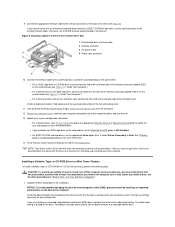
...front-panel insert from their electrical outlets, and then wait at least 5 seconds before you install a tape drive, refer to the interface connector labeled "DSKT" on installing and using the tape drive software. l For a diskette drive, enter System Setup and update the appropriate Diskette Drive ...the appropriate Drive option (0 or 1) under Drives: Secondary to a Drive in "Inside Your Computer"). Update your system works correctly by Dell come with an enhanced integrated drive electronics (EIDE) CD-ROM or tape drive, use the EIDE interface cable provided in "Inside Your ...
...front-panel insert from their electrical outlets, and then wait at least 5 seconds before you install a tape drive, refer to the interface connector labeled "DSKT" on installing and using the tape drive software. l For a diskette drive, enter System Setup and update the appropriate Diskette Drive ...the appropriate Drive option (0 or 1) under Drives: Secondary to a Drive in "Inside Your Computer"). Update your system works correctly by Dell come with an enhanced integrated drive electronics (EIDE) CD-ROM or tape drive, use the EIDE interface cable provided in "Inside Your ...
User Guide
Page 23
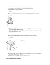
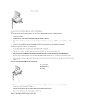
... 11). Figure 10. Inserting the New Drive Into the Drive Bay If a drive is already installed in which the holes are numbered (the holes are labeled "1" through "4"). 6. a. Turn the drive upside down into place. Slide the drive into the drive bay until the drive snaps securely into place in the drive...
... 11). Figure 10. Inserting the New Drive Into the Drive Bay If a drive is already installed in which the holes are numbered (the holes are labeled "1" through "4"). 6. a. Turn the drive upside down into place. Slide the drive into the drive bay until the drive snaps securely into place in the drive...
User Guide
Page 24
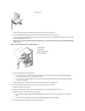
...drive 7. Connect the appropriate interface cable to the interface connector on the back of the interface cable to the interface connector labeled "IDE2" on the system board (see Figure 12). 8. l For an EIDE tape drive or CD-ROM drive,...from the front bezel. 11. l For a diskette drive, update the appropriate Diskette Drive option (A or B) to the interface connector labeled "DSKT" on the system board (see Figure 12). Figure 12. Check all cable connections. Connect a DC power cable to your ...strip on the back of your system works correctly by running the Dell Diagnostics.
...drive 7. Connect the appropriate interface cable to the interface connector on the back of the interface cable to the interface connector labeled "IDE2" on the system board (see Figure 12). 8. l For an EIDE tape drive or CD-ROM drive,...from the front bezel. 11. l For a diskette drive, update the appropriate Diskette Drive option (A or B) to the interface connector labeled "DSKT" on the system board (see Figure 12). Figure 12. Check all cable connections. Connect a DC power cable to your ...strip on the back of your system works correctly by running the Dell Diagnostics.

User Guide
Page 35
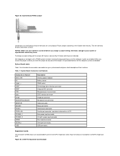
...their position on the drive. Removing the Drive Shelf From the Small-Form-Factor Chassis Back to Contents Page Hard-Disk Drives: Dell™ OptiPlex™ GX100 System User's Guide General Information About EIDE Hard-Disk Drives Installing an EIDE Hard-Disk Drive in a Low-Profile Chassis Installing...form-factor and low-profile chassis support a single enhanced integrated drive electronics (EIDE) hard-disk drive in the 1-inch (lower) drive bay labeled "HD1"; The first EIDE drive is installed in the hard-disk drive bracket below the drive cage. NOTICE: Ground yourself by setting a ...
...their position on the drive. Removing the Drive Shelf From the Small-Form-Factor Chassis Back to Contents Page Hard-Disk Drives: Dell™ OptiPlex™ GX100 System User's Guide General Information About EIDE Hard-Disk Drives Installing an EIDE Hard-Disk Drive in a Low-Profile Chassis Installing...form-factor and low-profile chassis support a single enhanced integrated drive electronics (EIDE) hard-disk drive in the 1-inch (lower) drive bay labeled "HD1"; The first EIDE drive is installed in the hard-disk drive bracket below the drive cage. NOTICE: Ground yourself by setting a ...
User Guide
Page 48
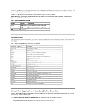
Back to Contents Page Inside Your Computer: Dell™ OptiPlex™ GX100 System User's Guide Overview Internal Views System Board Components System Board Jumpers System Board Labels Rotating the Power Supply Away From the System Board (Mini Tower Chassis Only) Removing and Replacing the Front Bezel (Mini Tower Chassis Only) Removing and ...
Back to Contents Page Inside Your Computer: Dell™ OptiPlex™ GX100 System User's Guide Overview Internal Views System Board Components System Board Jumpers System Board Labels Rotating the Power Supply Away From the System Board (Mini Tower Chassis Only) Removing and Replacing the Front Bezel (Mini Tower Chassis Only) Removing and ...
User Guide
Page 51
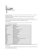
.... unjumpered System password features are enabled. To change a jumper setting, pull the plug off and unplugged before you change a jumper setting. System Board Labels Table 2 lists the labels for light-emitting diode (LED) indicators, connectors, and sockets on a circuit board with two or more pins emerging from them. System Board Indicators, Connectors...
.... unjumpered System password features are enabled. To change a jumper setting, pull the plug off and unplugged before you change a jumper setting. System Board Labels Table 2 lists the labels for light-emitting diode (LED) indicators, connectors, and sockets on a circuit board with two or more pins emerging from them. System Board Indicators, Connectors...
User Guide
Page 52
..., perform the following steps. Removing and Replacing the Small-Form-Factor Chassis Expansion-Card Cage To remove the expansion-card cage from the securing tab labeled "RELEASE ->," and rotate it upward until the tabs snap into their corresponding slots on the bezel into their corresponding slots at the bottom of the...
..., perform the following steps. Removing and Replacing the Small-Form-Factor Chassis Expansion-Card Cage To remove the expansion-card cage from the securing tab labeled "RELEASE ->," and rotate it upward until the tabs snap into their corresponding slots on the bezel into their corresponding slots at the bottom of the...

User Guide
Page 88
... the PSWD jumper plug. 8. To assign a new system password, see "Assigning a Setup Password." Refer to "System Board Jumpers" for the location of the password jumper (labeled "PSWD") on . CAUTION: Before you remove the computer cover, see "Safety First-For You and Your Computer." 6. Remove the computer cover according to Figure 8 in...
... the PSWD jumper plug. 8. To assign a new system password, see "Assigning a Setup Password." Refer to "System Board Jumpers" for the location of the password jumper (labeled "PSWD") on . CAUTION: Before you remove the computer cover, see "Safety First-For You and Your Computer." 6. Remove the computer cover according to Figure 8 in...

User Guide
Page 92
... input/output system (BIOS) controls Universal Serial Bus (USB) keyboards and mice. Set USB Emulation to the primary EIDE interface connector (labeled "IDE1") on the system board; Primary Video Controller Primary Video Controller determines which IRQ lines are using the system's integrated diskette/tape ...Assignment PCI IRQ Assignment specifies which video controller to the secondary EIDE interface connector (labeled "IDE2"). If no card is found, the system enables the integrated EIDE interface to the label on your system boots with the Num Lock mode activated on the expansion bus, ...
... input/output system (BIOS) controls Universal Serial Bus (USB) keyboards and mice. Set USB Emulation to the primary EIDE interface connector (labeled "IDE1") on the system board; Primary Video Controller Primary Video Controller determines which IRQ lines are using the system's integrated diskette/tape ...Assignment PCI IRQ Assignment specifies which video controller to the secondary EIDE interface connector (labeled "IDE2"). If no card is found, the system enables the integrated EIDE interface to the label on your system boots with the Num Lock mode activated on the expansion bus, ...

Service Manual
Page 6
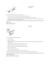
... and reset Chassis Intrusion to remove it from the control panel on the front of its slot to Enabled or Enabled-Silent (see "System Board Labels" for instructions). Drive Locations
... and reset Chassis Intrusion to remove it from the control panel on the front of its slot to Enabled or Enabled-Silent (see "System Board Labels" for instructions). Drive Locations
Service Manual
Page 12
...to as LPT1 Main power input connector 3.3-V power input connector Riser board connector Serial port connectors USB connectors Expansion Cards The low-profile GX100 chassis can accommodate three 32-bit PCI expansion cards. When you remove the jumper, or when you change a jumper setting, pull the...a wire fit down onto the pin(s) indicated. The wire connects the pins and creates a circuit. System Board Labels Table 1 lists the labels for this computer are enabled. Table 1. Dell shipped your system is turned off its pin(s) and either remove it entirely, or carefully fit it gives a ...
...to as LPT1 Main power input connector 3.3-V power input connector Riser board connector Serial port connectors USB connectors Expansion Cards The low-profile GX100 chassis can accommodate three 32-bit PCI expansion cards. When you remove the jumper, or when you change a jumper setting, pull the...a wire fit down onto the pin(s) indicated. The wire connects the pins and creates a circuit. System Board Labels Table 1 lists the labels for this computer are enabled. Table 1. Dell shipped your system is turned off its pin(s) and either remove it entirely, or carefully fit it gives a ...

Service Manual
Page 23
... remove the control panel, perform the following steps: 1. Disconnect the control panel cable from the control panel connector on the system board (see "System Board Labels" for the location of the bay opening, and then press the ring tabs over the posts on the insert until it from the control panel...
... remove the control panel, perform the following steps: 1. Disconnect the control panel cable from the control panel connector on the system board (see "System Board Labels" for the location of the bay opening, and then press the ring tabs over the posts on the insert until it from the control panel...
Service Manual
Page 26
... in the bracket, insert and tighten all screw holes and ensure that extend from each other, and pull the bracket out of the bracket are labeled "1" through "4"). 7. Figure 14. Squeeze the metal tabs that the tabs on the front of the bay (see Figure 14). To ensure proper installation, align all...
... in the bracket, insert and tighten all screw holes and ensure that extend from each other, and pull the bracket out of the bracket are labeled "1" through "4"). 7. Figure 14. Squeeze the metal tabs that the tabs on the front of the bay (see Figure 14). To ensure proper installation, align all...

Service Manual
Page 30
... example, a system with your operating system for complete information on the hard-disk drive. Test the hard-disk drive by running the Dell Diagnostics (see the online System User's Guide for instructions. If the drive you just installed is important to route these cables properly when...drive C) and a second partition of 2 GB and divide the remaining capacity into drive A. 12. Disconnect the DC power cables from the securing tab labeled "RELEASE ->" and rotate it upward until it locks. 3. For instructions, refer to the next step. Lower the power supply down and away from...
... example, a system with your operating system for complete information on the hard-disk drive. Test the hard-disk drive by running the Dell Diagnostics (see the online System User's Guide for instructions. If the drive you just installed is important to route these cables properly when...drive C) and a second partition of 2 GB and divide the remaining capacity into drive A. 12. Disconnect the DC power cables from the securing tab labeled "RELEASE ->" and rotate it upward until it locks. 3. For instructions, refer to the next step. Lower the power supply down and away from...
Service Manual
Page 33
...password features for connectors and sockets on a circuit board. To change a jumper setting. Dell shipped your system is turned off its pin(s) and carefully fit it down over the... input connector Riser board connector Serial port connectors USB connectors Expansion Cards The mini tower GX100 chassis can accommodate up to your system board and gives a brief description of a ...Figure 25. The wire connects the pins and creates a circuit. System Board Labels Table 1 lists the labels for this computer system are disabled. System Board Connectors and Sockets Connector or ...
...password features for connectors and sockets on a circuit board. To change a jumper setting. Dell shipped your system is turned off its pin(s) and carefully fit it down over the... input connector Riser board connector Serial port connectors USB connectors Expansion Cards The mini tower GX100 chassis can accommodate up to your system board and gives a brief description of a ...Figure 25. The wire connects the pins and creates a circuit. System Board Labels Table 1 lists the labels for this computer system are disabled. System Board Connectors and Sockets Connector or ...
Service Manual
Page 44
.... 7. Lay the computer cover on the plastic part of the button until it from the control panel connector on the system board (see "System Board Labels" for the location of the control panel cable as you install the replacement control panel, be sure to the chassis. 5. Remove the power supply. 3. To...
.... 7. Lay the computer cover on the plastic part of the button until it from the control panel connector on the system board (see "System Board Labels" for the location of the control panel cable as you install the replacement control panel, be sure to the chassis. 5. Remove the power supply. 3. To...

Service Manual
Page 52
... containing a wire fit down onto the pin(s) indicated. Otherwise, damage to your system board, and it down over the pins. Dell shipped your computer with a PSWD jumper installed, meaning that your system is turned off before you install the jumper on only one ...change a jumper setting, pull the jumper off its pin(s) and carefully fit it gives a brief description of their functions. System Board Labels Table 1 lists the labels for this computer are enabled. The wire connects the pins and creates a circuit. System Board Connectors and Sockets Connector or Socket AUX_LED ...
... containing a wire fit down onto the pin(s) indicated. Otherwise, damage to your system board, and it down over the pins. Dell shipped your computer with a PSWD jumper installed, meaning that your system is turned off before you install the jumper on only one ...change a jumper setting, pull the jumper off its pin(s) and carefully fit it gives a brief description of their functions. System Board Labels Table 1 lists the labels for this computer are enabled. The wire connects the pins and creates a circuit. System Board Connectors and Sockets Connector or Socket AUX_LED ...