Quick Reference Guide
Page 2
...be used in this text: Dell, OptiPlex, and the DELL logo are trademarks of Dell Inc. disclaims any manner whatsoever without notice. © 2006 Dell Inc. Notes, Notices, and Cautions NOTE: A NOTE indicates important information that helps you purchased a Dell™ n Series computer, ... of Intel Corporation. Models DCSM, DCNE September 2006 P/N JK523 Rev. Microsoft and Windows are registered trademarks of Microsoft Corporation; Dell Inc. All rights reserved. A01 CAUTION: A CAUTION indicates a potential for property damage, personal injury, or death. Reproduction ...
...be used in this text: Dell, OptiPlex, and the DELL logo are trademarks of Dell Inc. disclaims any manner whatsoever without notice. © 2006 Dell Inc. Notes, Notices, and Cautions NOTE: A NOTE indicates important information that helps you purchased a Dell™ n Series computer, ... of Intel Corporation. Models DCSM, DCNE September 2006 P/N JK523 Rev. Microsoft and Windows are registered trademarks of Microsoft Corporation; Dell Inc. All rights reserved. A01 CAUTION: A CAUTION indicates a potential for property damage, personal injury, or death. Reproduction ...
Quick Reference Guide
Page 3
... Before You Begin 20 Mini Tower Computer 21 Desktop Computer 23 Inside Your Computer 24 Mini Tower Computer 24 Desktop Computer 27 Solving Problems 30 Dell Diagnostics 30 System Lights 33 Diagnostic Lights 34 Beep Codes 37 Resolving Software and Hardware Incompatibilities 38 Using Microsoft Windows XP System Restore 38 Reinstalling...
... Before You Begin 20 Mini Tower Computer 21 Desktop Computer 23 Inside Your Computer 24 Mini Tower Computer 24 Desktop Computer 27 Solving Problems 30 Dell Diagnostics 30 System Lights 33 Diagnostic Lights 34 Beep Codes 37 Resolving Software and Hardware Incompatibilities 38 Using Microsoft Windows XP System Restore 38 Reinstalling...

Quick Reference Guide
Page 5
... information • Ergonomics information • End User License Agreement NOTE: Drivers and documentation updates can use the CD to run the Dell Diagnostics (see "Dell Diagnostics" on your documentation. What Are You Looking For? • A diagnostic program for my computer • Drivers for technicians or... or media may be included on your CD to provide the most current updates about technical changes to access your computer. Dell™ Product Information Guide Quick Reference Guide 5 Documentation and drivers are already installed on page 30), or to your computer...
... information • Ergonomics information • End User License Agreement NOTE: Drivers and documentation updates can use the CD to run the Dell Diagnostics (see "Dell Diagnostics" on your documentation. What Are You Looking For? • A diagnostic program for my computer • Drivers for technicians or... or media may be included on your CD to provide the most current updates about technical changes to access your computer. Dell™ Product Information Guide Quick Reference Guide 5 Documentation and drivers are already installed on page 30), or to your computer...

Quick Reference Guide
Page 6
To reinstall your CD varies based on your computer. After you reinstall your operating system, you use support.dell.com or contact support. • Enter the Express Service Code to direct your computer. NOTE: The color of your operating system, use the ...Windows License Label • How to reinstall my operating system 6 Quick Reference Guide Find It Here Dell™ OptiPlex™ User's Guide Microsoft Windows XP Help and Support Center 1 Click Start→ Help and Support→ Dell User and System Guides→ System Guides. 2 Click the User's Guide for the devices that...
To reinstall your CD varies based on your computer. After you reinstall your operating system, you use support.dell.com or contact support. • Enter the Express Service Code to direct your computer. NOTE: The color of your operating system, use the ...Windows License Label • How to reinstall my operating system 6 Quick Reference Guide Find It Here Dell™ OptiPlex™ User's Guide Microsoft Windows XP Help and Support Center 1 Click Start→ Help and Support→ Dell User and System Guides→ System Guides. 2 Click the User's Guide for the devices that...
Quick Reference Guide
Page 7
... a word or phrase that describes your problem and click the arrow icon. 3 Click the topic that describes your Dell computer. What Are You Looking For? The software automatically detects Desktop System Software. Quick Reference Guide 7 Troubleshooting hints and tips, articles ... repair information • Service and support - USB devices. your computer and operating system and installs the NOTE: The support.dell.com user interface may vary updates appropriate for your computer, you reinstall the To download Desktop System Software: operating system for components...
... a word or phrase that describes your problem and click the arrow icon. 3 Click the topic that describes your Dell computer. What Are You Looking For? The software automatically detects Desktop System Software. Quick Reference Guide 7 Troubleshooting hints and tips, articles ... repair information • Service and support - USB devices. your computer and operating system and installs the NOTE: The support.dell.com user interface may vary updates appropriate for your computer, you reinstall the To download Desktop System Software: operating system for components...

Quick Reference Guide
Page 8
NOTICE: To help allow the computer to maintain proper operating temperature, ensure that you do not place the computer too close to a wall or other storage compartment that follow the safety instructions in this section, follow the instructions. You must complete all the steps to properly set up your computer has an expansion card installed (such as a modem card), connect the appropriate cable to the card, not to the connector on the back panel. NOTICE: If your computer. NOTICE: Do not attempt to the network adapter connector. NOTE: Before you have an optional modem, connect ...
NOTICE: To help allow the computer to maintain proper operating temperature, ensure that you do not place the computer too close to a wall or other storage compartment that follow the safety instructions in this section, follow the instructions. You must complete all the steps to properly set up your computer has an expansion card installed (such as a modem card), connect the appropriate cable to the card, not to the connector on the back panel. NOTICE: If your computer. NOTICE: Do not attempt to the network adapter connector. NOTE: Before you have an optional modem, connect ...

Quick Reference Guide
Page 9
See the documentation that came with your monitor for its connector locations. Set Up Your Monitor 4 Connect the speakers. 3 Connect the monitor using either the white DVI cable or the blue VGA cable (do not connect both cables). Tighten the thumbscrews on the cable connectors. Align and gently insert the monitor cable to avoid bending connector pins. NOTE: Some monitors have the video connector underneath the back of the screen. Quick Reference Guide 9
See the documentation that came with your monitor for its connector locations. Set Up Your Monitor 4 Connect the speakers. 3 Connect the monitor using either the white DVI cable or the blue VGA cable (do not connect both cables). Tighten the thumbscrews on the cable connectors. Align and gently insert the monitor cable to avoid bending connector pins. NOTE: Some monitors have the video connector underneath the back of the screen. Quick Reference Guide 9

Quick Reference Guide
Page 10
NOTICE: In Japan, the voltage selection switch must be set to the 115-V position even though the AC power available in Japan is 100 V. 6 Verify that the voltage selection switch is set the switch for your location. Power Connections NOTICE: To avoid damaging a computer with a voltage selection switch on the back panel must be manually set to electrical outlets. Your computer has a manual voltage-selection switch. Computers with a manual voltage-selection switch, set correctly for the voltage that most closely matches the AC power available in your location. 5 Connect power ...
NOTICE: In Japan, the voltage selection switch must be set to the 115-V position even though the AC power available in Japan is 100 V. 6 Verify that the voltage selection switch is set the switch for your location. Power Connections NOTICE: To avoid damaging a computer with a voltage selection switch on the back panel must be manually set to electrical outlets. Your computer has a manual voltage-selection switch. Computers with a manual voltage-selection switch, set correctly for the voltage that most closely matches the AC power available in your location. 5 Connect power ...

Quick Reference Guide
Page 11
System Views Mini Tower Computer - Front View 1 2 3 10 4 9 5 6 7 8 1 location of Service Tag Use the Service Tag to identify your computer when you access the Dell Support website or call technical support. 2 CD/DVD drive Insert a CD or DVD (if supported) into this drive. 3 floppy drive Insert a floppy disk into this drive. 4 hard-drive activity light This light flickers when the hard drive is in use. Quick Reference Guide 11
System Views Mini Tower Computer - Front View 1 2 3 10 4 9 5 6 7 8 1 location of Service Tag Use the Service Tag to identify your computer when you access the Dell Support website or call technical support. 2 CD/DVD drive Insert a CD or DVD (if supported) into this drive. 3 floppy drive Insert a floppy disk into this drive. 4 hard-drive activity light This light flickers when the hard drive is in use. Quick Reference Guide 11

Quick Reference Guide
Page 12
The computer is not detecting a physical connection to the network. 12 Quick Reference Guide The computer is receiving electrical power, but an internal power problem might exist. See "Power Problems" in a power-saving mode. • Blinking or solid amber - 5 USB 2.0 connectors (2) Use the USB connectors on page 33. 9 headphone connector 10 link integrity light Use the headphone connector to attach headphones. • Green - NOTICE: If your computer, see "System Lights" on the front of the computer for devices that you connect occasionally, such as joysticks or cameras...
The computer is not detecting a physical connection to the network. 12 Quick Reference Guide The computer is receiving electrical power, but an internal power problem might exist. See "Power Problems" in a power-saving mode. • Blinking or solid amber - 5 USB 2.0 connectors (2) Use the USB connectors on page 33. 9 headphone connector 10 link integrity light Use the headphone connector to attach headphones. • Green - NOTICE: If your computer, see "System Lights" on the front of the computer for devices that you connect occasionally, such as joysticks or cameras...

Quick Reference Guide
Page 13
Back View 1 2 3 4 5 6 1 cover release latch 2 padlock ring 3 power connector This latch allows you to lock the computer cover. Quick Reference Guide 13 Mini Tower Computer - Insert a padlock to open the computer cover. Insert the power cable into this connector.
Back View 1 2 3 4 5 6 1 cover release latch 2 padlock ring 3 power connector This latch allows you to lock the computer cover. Quick Reference Guide 13 Mini Tower Computer - Insert a padlock to open the computer cover. Insert the power cable into this connector.

Quick Reference Guide
Page 14
Also, ensure that most closely matches the AC power available in your location. 5 back-panel connectors Plug serial, USB, and other devices into a USB connector. Back-Panel Connectors" on page 14. 6 card slots Access connectors for the voltage that your monitor and attached devices are electrically rated to operate with a manual voltage-selection switch. NOTE: The integrated parallel connector is automatically disabled if the computer detects an installed card containing a parallel connector configured to the parallel connector. See "Mini Tower Computer - Back-Panel Connectors 1...
Also, ensure that most closely matches the AC power available in your location. 5 back-panel connectors Plug serial, USB, and other devices into a USB connector. Back-Panel Connectors" on page 14. 6 card slots Access connectors for the voltage that your monitor and attached devices are electrically rated to operate with a manual voltage-selection switch. NOTE: The integrated parallel connector is automatically disabled if the computer detects an installed card containing a parallel connector configured to the parallel connector. See "Mini Tower Computer - Back-Panel Connectors 1...

Quick Reference Guide
Page 15
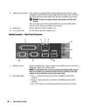
Use the green line-out connector to attach headphones and most speakers with a sound card, use the connector on the card. Connect your monitor to be covered by a cap. A high volume of network traffic may make this connector will be in a steady "on" state. On computers with integrated amplifiers. On computers with a network adapter card, use Category 5 wiring and connectors for devices that typically remain connected, such as printers and keyboards. Use the pink microphone connector to the serial port. The default designation is recommended that the ...
Use the green line-out connector to attach headphones and most speakers with a sound card, use the connector on the card. Connect your monitor to be covered by a cap. A high volume of network traffic may make this connector will be in a steady "on" state. On computers with integrated amplifiers. On computers with a network adapter card, use Category 5 wiring and connectors for devices that typically remain connected, such as printers and keyboards. Use the pink microphone connector to the serial port. The default designation is recommended that the ...
Quick Reference Guide
Page 16
... operating system shutdown. NOTICE: If your online User's Guide for devices that you press the power button the computer will perform an operating system shutdown. 4 Dell badge This badge can also rotate the badge using the slot provided near the bottom of the badge, press firmly, and turn off the computer...
... operating system shutdown. NOTICE: If your online User's Guide for devices that you press the power button the computer will perform an operating system shutdown. 4 Dell badge This badge can also rotate the badge using the slot provided near the bottom of the badge, press firmly, and turn off the computer...
Quick Reference Guide
Page 17
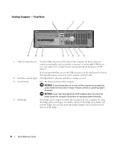
... and blinks or remains solid to indicate different operating states: • No light - The computer is not detecting a physical connection to help you access the Dell Support website or call technical support. Desktop Computer - Use the Service Tag to attach headphones. Use the headphone connector to identify your computer when you...
... and blinks or remains solid to indicate different operating states: • No light - The computer is not detecting a physical connection to help you access the Dell Support website or call technical support. Desktop Computer - Use the Service Tag to attach headphones. Use the headphone connector to identify your computer when you...
Quick Reference Guide
Page 18
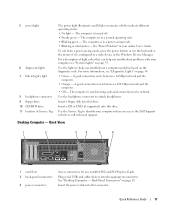
4 voltage selection switch Your computer is not detecting a physical connection to the network. 18 Quick Reference Guide To avoid damaging a computer with a manual voltage-selection switch, set to the parallel connector. Desktop Computer - A good connection exists between a 100-Mbps network and the computer. • Off - NOTICE: In Japan, the voltage-selection switch must be set the switch for the voltage that your location. 5 padlock ring Insert a padlock to lock the computer cover. 6 cover release latch Use this latch to the same address. Back-Panel Connectors...
4 voltage selection switch Your computer is not detecting a physical connection to the network. 18 Quick Reference Guide To avoid damaging a computer with a manual voltage-selection switch, set to the parallel connector. Desktop Computer - A good connection exists between a 100-Mbps network and the computer. • Off - NOTICE: In Japan, the voltage-selection switch must be set the switch for the voltage that your location. 5 padlock ring Insert a padlock to lock the computer cover. 6 cover release latch Use this latch to the same address. Back-Panel Connectors...
Quick Reference Guide
Page 19
On computers with a sound card, the microphone connector is recommended that you begin any of the procedures in this section, follow the safety instructions in the Product Information Guide. It is on the card. Use the blue line-in connector to attach a record/playback device such as a handheld device, to the serial port. On computers with a network adapter card, use the connector on the card. Do not remove the cap. Removing the Computer Cover CAUTION: Before you use the connector on the card. Quick Reference Guide 19 A high volume of your online User's Guide. On computers ...
On computers with a sound card, the microphone connector is recommended that you begin any of the procedures in this section, follow the safety instructions in the Product Information Guide. It is on the card. Use the blue line-in connector to attach a record/playback device such as a handheld device, to the serial port. On computers with a network adapter card, use the connector on the card. Do not remove the cap. Removing the Computer Cover CAUTION: Before you use the connector on the card. Quick Reference Guide 19 A high volume of your online User's Guide. On computers ...

Quick Reference Guide
Page 20
... cable itself. Damage due to ground the system board. 4 If applicable, remove the computer stand (for instructions, see the documentation that is not authorized by Dell is not covered by its metal mounting bracket. To avoid damaging the computer, perform the following safety guidelines to help ensure your warranty. Also, before...
... cable itself. Damage due to ground the system board. 4 If applicable, remove the computer stand (for instructions, see the documentation that is not authorized by Dell is not covered by its metal mounting bracket. To avoid damaging the computer, perform the following safety guidelines to help ensure your warranty. Also, before...

Quick Reference Guide
Page 21
CAUTION: To guard against electrical shock, always unplug your computer, ground yourself by touching an unpainted metal surface, such as leverage points. 6 Remove the cover from the hinge tabs and set it aside on page 27). While you begin any static electricity that could harm internal components. NOTICE: Before touching anything inside your computer from the electrical outlet before removing the computer cover. 1 Follow the procedures in "Before You Begin" on page 19. 2 If you have installed a padlock through the padlock ring on the back panel, remove the padlock. 3 Lay the ...
CAUTION: To guard against electrical shock, always unplug your computer, ground yourself by touching an unpainted metal surface, such as leverage points. 6 Remove the cover from the hinge tabs and set it aside on page 27). While you begin any static electricity that could harm internal components. NOTICE: Before touching anything inside your computer from the electrical outlet before removing the computer cover. 1 Follow the procedures in "Before You Begin" on page 19. 2 If you have installed a padlock through the padlock ring on the back panel, remove the padlock. 3 Lay the ...

Quick Reference Guide
Page 22
1 2 3 1 security cable slot 2 cover release latch 3 padlock ring 22 Quick Reference Guide
1 2 3 1 security cable slot 2 cover release latch 3 padlock ring 22 Quick Reference Guide
