
Service Manual
Page 4
Chapter 3 Beep Codes and Error Messages 3-1 POST Beep Codes 3-1 System Error Messages 3-3 Running the Dell Diagnostics 3-6 Chapter 4 Removing and Replacing Parts 4-1 Recommended Tools 4-1 Screw Identification and Tightening 4-2 Precautionary Measures 4-3 ZIF Connectors 4-6 Exploded Views of ...and Assemblies 4-7 Factory Repair Parts and Assemblies 4-11 Deleting the Password 4-18 Hard-Disk Drive 4-19 Diskette Drive 4-20 CD-ROM 4-21 Memory Module 4-22 LCD Assembly 4-23 Front Bezel 4-24 LCD Panel 4-25 Inverter Board 4-26 Microphone 4-26 LCD Assembly Latches 4-27 Power/Suspend ...
Chapter 3 Beep Codes and Error Messages 3-1 POST Beep Codes 3-1 System Error Messages 3-3 Running the Dell Diagnostics 3-6 Chapter 4 Removing and Replacing Parts 4-1 Recommended Tools 4-1 Screw Identification and Tightening 4-2 Precautionary Measures 4-3 ZIF Connectors 4-6 Exploded Views of ...and Assemblies 4-7 Factory Repair Parts and Assemblies 4-11 Deleting the Password 4-18 Hard-Disk Drive 4-19 Diskette Drive 4-20 CD-ROM 4-21 Memory Module 4-22 LCD Assembly 4-23 Front Bezel 4-24 LCD Panel 4-25 Inverter Board 4-26 Microphone 4-26 LCD Assembly Latches 4-27 Power/Suspend ...

Service Manual
Page 5
... 4-43 Cache Board 4-45 Index Figures Figure 1-1. Back View of the Portable Computer 1-2 Figure 1-2. Releasing a ZIF Connector 4-6 Figure 4-9. Hard-Disk Drive Disassembly 4-19 Figure 4-15. Memory Module Removal 4-22 Figure 4-18. Inverter Board Removal 4-26 Figure 4-22. Front View of the Portable Computer 1-2 Figure 1-3. Hard-Disk Drive Removal 4-4 Figure 4-5. Exploded View...
... 4-43 Cache Board 4-45 Index Figures Figure 1-1. Back View of the Portable Computer 1-2 Figure 1-2. Releasing a ZIF Connector 4-6 Figure 4-9. Hard-Disk Drive Disassembly 4-19 Figure 4-15. Memory Module Removal 4-22 Figure 4-18. Inverter Board Removal 4-26 Figure 4-22. Front View of the Portable Computer 1-2 Figure 1-3. Hard-Disk Drive Removal 4-4 Figure 4-5. Exploded View...
Service Manual
Page 11
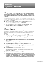
...the components and subsystems of 4-, 8-, or 16-MB memory modules in the memory upgrade sockets on the main board. The individual model names within the Dell Latitude LM portable family indicate the type and operating frequency of nonremovable main memory on the main board. • An 11.3-inch...Pentium micro- processor and an SVGA (S) dual-scan (D) STN LCD. • The Dell Latitude LM P-133ST contains a 133-MHz Pentium micro- processor and an SVGA (S) active-matrix (T) TFT LCD. The memory capacity can be increased up to the standard features found in suspend mode. The CD-ROM...
...the components and subsystems of 4-, 8-, or 16-MB memory modules in the memory upgrade sockets on the main board. The individual model names within the Dell Latitude LM portable family indicate the type and operating frequency of nonremovable main memory on the main board. • An 11.3-inch...Pentium micro- processor and an SVGA (S) dual-scan (D) STN LCD. • The Dell Latitude LM P-133ST contains a 133-MHz Pentium micro- processor and an SVGA (S) active-matrix (T) TFT LCD. The memory capacity can be increased up to the standard features found in suspend mode. The CD-ROM...

Service Manual
Page 18
... capacities . . 4, 8, and 16 MB; Technical Specifications Microprocessor Microprocessor type Intel Pentium microprocessor Microprocessor speed 100 or 133 MHz Internal cache memory 16 KB External cache 256 KB Math coprocessor internal to the microprocessor Chip Set and Bus System chip set Intel 430MX PCIset Data bus width ... II cards or one type III card) Cards supported 3.3- must be installed in matched pairs Standard RAM 8 MB on system board Maximum RAM 40 MB 1-8 Dell Latitude LM Systems Service Manual Technical Specifications Table 1-2.
... capacities . . 4, 8, and 16 MB; Technical Specifications Microprocessor Microprocessor type Intel Pentium microprocessor Microprocessor speed 100 or 133 MHz Internal cache memory 16 KB External cache 256 KB Math coprocessor internal to the microprocessor Chip Set and Bus System chip set Intel 430MX PCIset Data bus width ... II cards or one type III card) Cards supported 3.3- must be installed in matched pairs Standard RAM 8 MB on system board Maximum RAM 40 MB 1-8 Dell Latitude LM Systems Service Manual Technical Specifications Table 1-2.

Service Manual
Page 19
..., bidirectional, EPP 1.9, or ECP Monitor one 15-hole connector PS/2 keyboard/mouse one 6-pin mini-DIN Infrared one 25-hole connector; Technical Specifications (Continued) Memory (Continued) Memory access time: tRAC 70 ns tCAC 20 ns BIOS address F000:0000 Connectors Serial (DTE one 9-pin connector; 16,550-compatible, 16-byte buffer Parallel...
..., bidirectional, EPP 1.9, or ECP Monitor one 15-hole connector PS/2 keyboard/mouse one 6-pin mini-DIN Infrared one 25-hole connector; Technical Specifications (Continued) Memory (Continued) Memory access time: tRAC 70 ns tCAC 20 ns BIOS address F000:0000 Connectors Serial (DTE one 9-pin connector; 16,550-compatible, 16-byte buffer Parallel...

Service Manual
Page 20
Table 1-2. Technical Specifications (Continued) Video Video type 64-bit (128-bit hardware accelerated) PCI Video controller NeoMagic 2070 Video memory 896 KB Active-Matrix Display Type active-matrix color (TFT) Dimensions: Height 184.5 mm (7.3 inches) Width 246.0 mm (9.7 inches) Diagonal 307.5 mm (12.1 inches) Maximum ...) Maximum resolution 800 x 600 pixels; 256 colors Refresh rate (typical 70 Hz Response time (typical) . . . . . 300 ms Operating angle 0° (closed) to 135° 1-10 Dell Latitude LM Systems Service Manual
Table 1-2. Technical Specifications (Continued) Video Video type 64-bit (128-bit hardware accelerated) PCI Video controller NeoMagic 2070 Video memory 896 KB Active-Matrix Display Type active-matrix color (TFT) Dimensions: Height 184.5 mm (7.3 inches) Width 246.0 mm (9.7 inches) Diagonal 307.5 mm (12.1 inches) Maximum ...) Maximum resolution 800 x 600 pixels; 256 colors Refresh rate (typical 70 Hz Response time (typical) . . . . . 300 ms Operating angle 0° (closed) to 135° 1-10 Dell Latitude LM Systems Service Manual

Service Manual
Page 26
... it is not in the following : a. c. Remove the diskette drive (if installed), verify that its associated buttons operate freely. 2-2 Dell Latitude LM Systems Service Manual Then proceed to step 2. 2. Remove any installed PC Cards from an AC adapter, verify the following procedure, see if...step 2. Then proceed to step 3. 3. If there is off the computer. If the display is a memory area problem and the computer has memory modules, remove the memory modules from battery power, remove any installed batteries, verify that the touch pad and its keys operate freely....
... it is not in the following : a. c. Remove the diskette drive (if installed), verify that its associated buttons operate freely. 2-2 Dell Latitude LM Systems Service Manual Then proceed to step 2. 2. Remove any installed PC Cards from an AC adapter, verify the following procedure, see if...step 2. Then proceed to step 3. 3. If there is off the computer. If the display is a memory area problem and the computer has memory modules, remove the memory modules from battery power, remove any installed batteries, verify that the touch pad and its keys operate freely....

Service Manual
Page 29
...For instructions, see Chapter 3, "Troubleshooting Your Computer," in the Reference and Troubleshooting Guide or the "Contacting Dell" section of the problem, contact Dell for technical assistance. Initial Procedures 2-5 If you suspect that the computer failure is assigned to the proper troubleshooting...," in the Reference and Troubleshooting Guide. Disconnect all peripherals and remove all PC Cards to the computer may require dedicated memory spaces, interrupt levels, and/or DMA channels. Eliminating Resource Conflicts Devices within or connected to make sure that resource conflicts...
...For instructions, see Chapter 3, "Troubleshooting Your Computer," in the Reference and Troubleshooting Guide or the "Contacting Dell" section of the problem, contact Dell for technical assistance. Initial Procedures 2-5 If you suspect that the computer failure is assigned to the proper troubleshooting...," in the Reference and Troubleshooting Guide. Disconnect all peripherals and remove all PC Cards to the computer may require dedicated memory spaces, interrupt levels, and/or DMA channels. Eliminating Resource Conflicts Devices within or connected to make sure that resource conflicts...

Service Manual
Page 32
... bus Check ROM copyright notice failure Faulty main board Interrupt mask register failure Faulty main board 3-2 Dell Latitude LM Systems Service Manual POST Beep Codes Error Probable Causes Memory module not being properly identified or used Faulty memory module or faulty main board ROM BIOS checksum failure Faulty main board DRAM refresh failure Faulty main...
... bus Check ROM copyright notice failure Faulty main board Interrupt mask register failure Faulty main board 3-2 Dell Latitude LM Systems Service Manual POST Beep Codes Error Probable Causes Memory module not being properly identified or used Faulty memory module or faulty main board ROM BIOS checksum failure Faulty main board DRAM refresh failure Faulty main...

Service Manual
Page 33
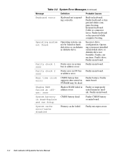
... computer. Incorrect drive configuration. Faulty connections. Keyboard controller error Keyboard controller faulty. Beep Codes and Error Messages 3-3 seated memory mod- ule. Corrupted hard-disk drive boot sector or configuration file. Faulty hard-disk drive. Table 3-2. Faulty main board... or during normal computer operation. Faulty main board. Faulty or improperly seated memory module. Faulty main board. Faulty main board. Failing bits: nnnn Memory failed at memory address nnnn. Fixed disk 0 failure Hard-disk drive not responding to commands...
... computer. Incorrect drive configuration. Faulty connections. Keyboard controller error Keyboard controller faulty. Beep Codes and Error Messages 3-3 seated memory mod- ule. Corrupted hard-disk drive boot sector or configuration file. Faulty hard-disk drive. Table 3-2. Faulty main board... or during normal computer operation. Faulty main board. Faulty or improperly seated memory module. Faulty main board. Faulty main board. Failing bits: nnnn Memory failed at memory address nnnn. Fixed disk 0 failure Hard-disk drive not responding to commands...
Service Manual
Page 34
... offset: nnnn Shadow RAM failed at address nnnn. Faulty drive. Faulty main board. Faulty supports data stored in system Faulty main board. ule. Faulty microprocessor. 3-4 Dell Latitude LM Systems Service Manual External keyboard: Cable or connector loose. at Faulty or improperly address nnnn. NVRAM may be found Operating system cannot be dead. Parity... I/O bus Faulty main board. Operating system not found on harddisk drive or on hard-disk drive or diskette drive not bootable. Incorrect drive configuration. seated memory mod-
... offset: nnnn Shadow RAM failed at address nnnn. Faulty drive. Faulty main board. Faulty supports data stored in system Faulty main board. ule. Faulty microprocessor. 3-4 Dell Latitude LM Systems Service Manual External keyboard: Cable or connector loose. at Faulty or improperly address nnnn. NVRAM may be found Operating system cannot be dead. Parity... I/O bus Faulty main board. Operating system not found on harddisk drive or on hard-disk drive or diskette drive not bootable. Incorrect drive configuration. seated memory mod-

Service Manual
Page 35
System RAM failed at address nnnn in CMOS. Faulty or improperly seated memory module. board malfunctioning. BIOS has been updated. System RAM failed at which error was detected. Faulty main board. System timer error Timer circuit on main ...-run Setup CMOS has been corrupted or modified, possibly by an application program that changes data stored in the 64-KB block at offset: nnnn Memory not operating correctly.
System RAM failed at address nnnn in CMOS. Faulty or improperly seated memory module. board malfunctioning. BIOS has been updated. System RAM failed at which error was detected. Faulty main board. System timer error Timer circuit on main ...-run Setup CMOS has been corrupted or modified, possibly by an application program that changes data stored in the 64-KB block at offset: nnnn Memory not operating correctly.

Service Manual
Page 36
..., always use a backup copy of the computer 3-6 Dell Latitude LM Systems Service Manual Tests the mouse/touch pad subsystem • Diskette Drives - Tests the serial communications port • Parallel Ports - If a main memory error is loading. Tests a network controller and its ...associated interface NOTE: This test does not apply to Dell Latitude LM computers. • Network Interface - Runs all tests for loading the diagnostics. ...
..., always use a backup copy of the computer 3-6 Dell Latitude LM Systems Service Manual Tests the mouse/touch pad subsystem • Diskette Drives - Tests the serial communications port • Parallel Ports - If a main memory error is loading. Tests a network controller and its ...associated interface NOTE: This test does not apply to Dell Latitude LM computers. • Network Interface - Runs all tests for loading the diagnostics. ...

Service Manual
Page 50
...LMP Latch, LCD, left LTCH,PLSTC,LF,LCD,LMP Memory Memory module, 8-MB, service kit* CUS,MEM,8M,LMP Memory module, two 4-MB SIMM,4MB,LXP Memory module, 16-MB, service kit* CUS,MEM,16M,LMP Memory module, two 8-MB DIMM,8MB,2X32,TL,LXP Memory module, 32-MB, service kit* CUS,MEM,32M...,LMP Memory module, two 16-MB DIMM,16MB,LXP Miscellaneous Parts Cover, front, hard-disk drive BZL,HDD,LMP Cover, hinge/infrared lens, right CVR,PLSTC,IR,LMP Cover, hinge, left CVR,HNG,LF,LMP Cover, keyboard screws CVR,SCR,KYBD,LMP * Customer-replaceable unit (CRU) 4-14 Dell Latitude LM Systems ...
...LMP Latch, LCD, left LTCH,PLSTC,LF,LCD,LMP Memory Memory module, 8-MB, service kit* CUS,MEM,8M,LMP Memory module, two 4-MB SIMM,4MB,LXP Memory module, 16-MB, service kit* CUS,MEM,16M,LMP Memory module, two 8-MB DIMM,8MB,2X32,TL,LXP Memory module, 32-MB, service kit* CUS,MEM,32M...,LMP Memory module, two 16-MB DIMM,16MB,LXP Miscellaneous Parts Cover, front, hard-disk drive BZL,HDD,LMP Cover, hinge/infrared lens, right CVR,PLSTC,IR,LMP Cover, hinge, left CVR,HNG,LF,LMP Cover, keyboard screws CVR,SCR,KYBD,LMP * Customer-replaceable unit (CRU) 4-14 Dell Latitude LM Systems ...

Service Manual
Page 51
...-cable CVR,HNG,CTR,LMP Insulator, expansion connector INSUL,CON,DCKG,LMP Insulator, main board INSUL,MYLAR,I/O,LMP Bracket, I/O BRKT,I/O,LMP Door, I/O DOOR,I/O,LMP Door, memory module DOOR,RAM,LMP Guide, hard-disk drive, left GDE,RL,LF,HD,LMP Assembly, base CVR,BTM,PLSTC,SYS,BAS,LMP Door, expansion connector...,FLH,PNH,MS,ZPS,HD Screw, heat sink SCR,2X.4X6,PHH,MS,ZPS Screw, keyboard SCR,3X.5X3,FLH,PNH,MS,ZPS, KYBD Screw, memory module door SCR,2X.4X5,FLH,MS,BLO Screw, I/O panel standoff SCR,440X.23,JK,MS,ZPS Screw, expansion connector (dock-
...-cable CVR,HNG,CTR,LMP Insulator, expansion connector INSUL,CON,DCKG,LMP Insulator, main board INSUL,MYLAR,I/O,LMP Bracket, I/O BRKT,I/O,LMP Door, I/O DOOR,I/O,LMP Door, memory module DOOR,RAM,LMP Guide, hard-disk drive, left GDE,RL,LF,HD,LMP Assembly, base CVR,BTM,PLSTC,SYS,BAS,LMP Door, expansion connector...,FLH,PNH,MS,ZPS,HD Screw, heat sink SCR,2X.4X6,PHH,MS,ZPS Screw, keyboard SCR,3X.5X3,FLH,PNH,MS,ZPS, KYBD Screw, memory module door SCR,2X.4X5,FLH,MS,BLO Screw, I/O panel standoff SCR,440X.23,JK,MS,ZPS Screw, expansion connector (dock-

Service Manual
Page 52
... Repair Parts and Assemblies (Continued) Part or Assembly Name Order Name Service Documentation (Continued) Technical sheet, whole unit replacement TSH,WUE,SVC,LMP Technical sheet, memory module TSH,MEM,LMP,ENG Software Diagnostics diskette, service kit, U.S. KIT,DSK,DIAG,V3.58,F3,US Diagnostics diskette, service kit, Spanish KIT,DSK,DIAG...,FLEX,TPAD,LMP Card, touch-pad switch SWT,CRD,TPAD,LMP Card, touch pad CRD,TPAD,LMP Insulator, touch pad INSUL,MYLAR,TPAD,LMP 4-16 Dell Latitude LM Systems Service Manual
... Repair Parts and Assemblies (Continued) Part or Assembly Name Order Name Service Documentation (Continued) Technical sheet, whole unit replacement TSH,WUE,SVC,LMP Technical sheet, memory module TSH,MEM,LMP,ENG Software Diagnostics diskette, service kit, U.S. KIT,DSK,DIAG,V3.58,F3,US Diagnostics diskette, service kit, Spanish KIT,DSK,DIAG...,FLEX,TPAD,LMP Card, touch-pad switch SWT,CRD,TPAD,LMP Card, touch pad CRD,TPAD,LMP Insulator, touch pad INSUL,MYLAR,TPAD,LMP 4-16 Dell Latitude LM Systems Service Manual

Service Manual
Page 58
...memory module. Install two 16-MB memory modules. 4-22 Dell Latitude LM Systems Service Manual Turn the computer over, and remove the two memory-module cover screws. 2. Install two 8-MB memory modules. • 40 MB - MM1 MM2 cover (screws MM1 and MM2 are possible: • 16 MB - To reinstall a memory module, both memory... slots must have the same memory capacity. The following combinations are 3.5 mm) 3.5 mm memory module (2) retainer clip Figure 4-17. Memory Module Removal To remove a memory module, follow these steps: 1. Gently rotate the memory module toward you, and then...
...memory module. Install two 16-MB memory modules. 4-22 Dell Latitude LM Systems Service Manual Turn the computer over, and remove the two memory-module cover screws. 2. Install two 8-MB memory modules. • 40 MB - MM1 MM2 cover (screws MM1 and MM2 are possible: • 16 MB - To reinstall a memory module, both memory... slots must have the same memory capacity. The following combinations are 3.5 mm) 3.5 mm memory module (2) retainer clip Figure 4-17. Memory Module Removal To remove a memory module, follow these steps: 1. Gently rotate the memory module toward you, and then...

Service Manual
Page 85
M main battery location, 4-3 removal, 4-3 main-battery compartment, 1-2 memory maximum configuration, 1-1 system memory, 1-1 memory module capacities supported, 1-1 removal, 4-22 microphone, 1-2, 4-26 microphone jack, 1-2 microprocessor, 1-1 N naming conventions, 4-17 Num Lock indicator, 1-3 O options bay, 1-2 P Pad Lock indicator, 1-3 parallel port connector, 1-2 password ...
M main battery location, 4-3 removal, 4-3 main-battery compartment, 1-2 memory maximum configuration, 1-1 system memory, 1-1 memory module capacities supported, 1-1 removal, 4-22 microphone, 1-2, 4-26 microphone jack, 1-2 microprocessor, 1-1 N naming conventions, 4-17 Num Lock indicator, 1-3 O options bay, 1-2 P Pad Lock indicator, 1-3 parallel port connector, 1-2 password ...

Service Manual Update
Page 1
...microprocessor with MMX technology has twice the internal cache memory (32 KB) as the standard Pentium microprocessor. • A NeoMagic 2093 video controller for a video subsystem that includes 1.1 MB of the figures in the Dell Latitude LM Service Manual. Conductive sponges or EMI shields may ...not appear exactly as shown in some of video memory. • 6X or 10X CD-ROM drives. • Your computer may have been added. Dell Latitude LM Service Manual Update 1 Dell ®Latitude® LM Service Manual...
...microprocessor with MMX technology has twice the internal cache memory (32 KB) as the standard Pentium microprocessor. • A NeoMagic 2093 video controller for a video subsystem that includes 1.1 MB of the figures in the Dell Latitude LM Service Manual. Conductive sponges or EMI shields may ...not appear exactly as shown in some of video memory. • 6X or 10X CD-ROM drives. • Your computer may have been added. Dell Latitude LM Service Manual Update 1 Dell ®Latitude® LM Service Manual...

Service Manual Update
Page 2
...microprocessor) External cache 256-KB write-back SRAM Math coprocessor internal to the microprocessor Memory Architecture fast-page mode, two-way interleaved Memory module capacities 4, 8, 16, and 32 MB; memory modules must be installed in Appendix A. Technical Specifications The following information updates Table... or two 32-MB modules) Standard RAM 16 MB (8 MB of nonremovable memory on the system board and two installed 4-MB memory modules) Maximum RAM 72 MB Memory access time: tRAC 70 ns tCAC 20 ns BIOS address F000:0000 2 Dell Latitude LM Service Manual Update
...microprocessor) External cache 256-KB write-back SRAM Math coprocessor internal to the microprocessor Memory Architecture fast-page mode, two-way interleaved Memory module capacities 4, 8, 16, and 32 MB; memory modules must be installed in Appendix A. Technical Specifications The following information updates Table... or two 32-MB modules) Standard RAM 16 MB (8 MB of nonremovable memory on the system board and two installed 4-MB memory modules) Maximum RAM 72 MB Memory access time: tRAC 70 ns tCAC 20 ns BIOS address F000:0000 2 Dell Latitude LM Service Manual Update


