User Manual
Page 2
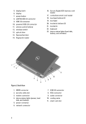
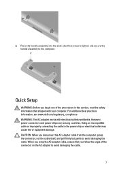
...security cable slot 3. power connector 6. power button 8. eSATA/USB 2.0 connector 9. volume control buttons 12. VGA connector 9. audio connector 10. cooling vents 11. display 7. Secure Digital (SD) memory-card reader 17. touchpad buttons (2) 19. touchpad 20. device status lights (power, hard... disk, and battery) 5. display latch 6. USB 3.0 connector 10. powered USB 3.0 connector 11. wireless switch 13. optical drive 14. trackstick buttons (3) 21. trackstick...
...security cable slot 3. power connector 6. power button 8. eSATA/USB 2.0 connector 9. volume control buttons 12. VGA connector 9. audio connector 10. cooling vents 11. display 7. Secure Digital (SD) memory-card reader 17. touchpad buttons (2) 19. touchpad 20. device status lights (power, hard... disk, and battery) 5. display latch 6. USB 3.0 connector 10. powered USB 3.0 connector 11. wireless switch 13. optical drive 14. trackstick buttons (3) 21. trackstick...
User Manual
Page 4
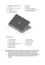
...touchpad buttons (2) 19. modem connector 4. USB 3.0 connector 9. Do not store your Dell computer in the air vents. The computer turns on the fan when the computer gets hot. network connector 2. power connector 6. device status lights (hard disk, battery, and wireless) Figure 4. smart...indicate a problem with the fan or the computer. 4 volume control buttons 23. USB 2.0 connector 7. trackstick buttons (3) 20. security cable slot 3. Fan noise is running. Restricting the airflow can damage the computer or cause a fire. keyboard 22. VGA connector 8. audio ...
...touchpad buttons (2) 19. modem connector 4. USB 3.0 connector 9. Do not store your Dell computer in the air vents. The computer turns on the fan when the computer gets hot. network connector 2. power connector 6. device status lights (hard disk, battery, and wireless) Figure 4. smart...indicate a problem with the fan or the computer. 4 volume control buttons 23. USB 2.0 connector 7. trackstick buttons (3) 20. security cable slot 3. Fan noise is running. Restricting the airflow can damage the computer or cause a fire. keyboard 22. VGA connector 8. audio ...
User Manual
Page 6
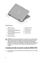
..., while it is normal and does not indicate a problem with the fan or the computer. Installing Handle Assembly (Latitude E6430 ATG) 1. security cable slot 3. power connector 6. HDMI connector 2. Restricting the airflow can damage the computer or cause a fire. The computer turns on the... or allow dust to unlock and remove the covering plugs from their slots. 6 device status lights (power, hard disk, and battery) 5. modem connector /WWAN pass- Do not store your Dell computer in the air vents. cooling vents 11. Fan noise is running. through (optional) 4. Back ...
..., while it is normal and does not indicate a problem with the fan or the computer. Installing Handle Assembly (Latitude E6430 ATG) 1. security cable slot 3. power connector 6. HDMI connector 2. Restricting the airflow can damage the computer or cause a fire. The computer turns on the... or allow dust to unlock and remove the covering plugs from their slots. 6 device status lights (power, hard disk, and battery) 5. modem connector /WWAN pass- Do not store your Dell computer in the air vents. cooling vents 11. Fan noise is running. through (optional) 4. Back ...
User Manual
Page 7
... additional best practices information, see www.dell.com/regulatory_compliance WARNING: The AC adapter works with your computer. When you disconnect the AC adapter cable from the computer, grasp the connector, not the cable itself, and pull firmly but gently to avoid damaging the cable. 7 However, power connectors and power strips vary among countries. 2. CAUTION: When you...
... additional best practices information, see www.dell.com/regulatory_compliance WARNING: The AC adapter works with your computer. When you disconnect the AC adapter cable from the computer, grasp the connector, not the cable itself, and pull firmly but gently to avoid damaging the cable. 7 However, power connectors and power strips vary among countries. 2. CAUTION: When you...
User Manual
Page 8
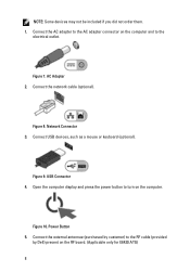
... as a mouse or keyboard (optional). Open the computer display and press the power button to the electrical outlet. AC Adapter 2. Figure 9. Network Connector 3. Connect the network cable (optional). Figure 8. Power Button 5. Figure 7. Connect the AC adapter to the AC adapter connector on... the computer and to turn on the RF board. (Applicable only for E6430 ATG) 8 USB Connector 4. Connect the external antennae (purchased by customer) to the RF cable (provided by Dell...
... as a mouse or keyboard (optional). Open the computer display and press the power button to the electrical outlet. AC Adapter 2. Figure 9. Network Connector 3. Connect the network cable (optional). Figure 8. Power Button 5. Figure 7. Connect the AC adapter to the AC adapter connector on... the computer and to turn on the RF board. (Applicable only for E6430 ATG) 8 USB Connector 4. Connect the external antennae (purchased by customer) to the RF cable (provided by Dell...

Owners Manual
Page 4
... Coin-Cell Battery...31 Removing the ExpressCard Cage...31 Installing the ExpressCard Cage...32 Removing the Power-Connector Port...32 Installing the Power-Connector Port...33 Removing the Power LED Board...34 Installing the Power LED Board...35 Removing the Input/Output (I/O) Board...35 Installing the Input Output (I/O) Board......Display Hinges...56 Installing the Display Hinges...57 Removing the Camera...58 Installing the Camera...58 Removing the LVDS and Camera Cable...59 Installing the LVDS and Camera Cable...60 3 Additional Information...61 Docking Port Information...61 4 System Setup...63
... Coin-Cell Battery...31 Removing the ExpressCard Cage...31 Installing the ExpressCard Cage...32 Removing the Power-Connector Port...32 Installing the Power-Connector Port...33 Removing the Power LED Board...34 Installing the Power LED Board...35 Removing the Input/Output (I/O) Board...35 Installing the Input Output (I/O) Board......Display Hinges...56 Installing the Display Hinges...57 Removing the Camera...58 Installing the Camera...58 Removing the LVDS and Camera Cable...59 Installing the LVDS and Camera Cable...60 3 Additional Information...61 Docking Port Information...61 4 System Setup...63

Owners Manual
Page 32
... secure the ExpressCard cage to the computer. 3. Follow the procedures in After Working Inside Your Computer. 4. Disconnect the power-connector cable from the computer. Remove: a) battery b) base cover 3. Installing the ExpressCard Cage 1. Removing the Power-Connector Port 1. Install: a) palmrest b) display assembly c) keyboard d) keyboard trim e) bluetooth card f) hard drive g) base cover h) battery 4. Remove the...
... secure the ExpressCard cage to the computer. 3. Follow the procedures in After Working Inside Your Computer. 4. Disconnect the power-connector cable from the computer. Remove: a) battery b) base cover 3. Installing the ExpressCard Cage 1. Removing the Power-Connector Port 1. Install: a) palmrest b) display assembly c) keyboard d) keyboard trim e) bluetooth card f) hard drive g) base cover h) battery 4. Remove the...

Owners Manual
Page 33
... Working Inside Your Computer. 33 4. Connect the power-connector cable to the computer. 4. Installing the Power-Connector Port 1. Tighten the screw to secure the power-connector bracket to the computer. 2. Install: a) base cover b) battery 6. Remove the screw that secures the power-connector bracket to the computer. 5. Remove the power-connector bracket from the computer. Follow the...
... Working Inside Your Computer. 33 4. Connect the power-connector cable to the computer. 4. Installing the Power-Connector Port 1. Tighten the screw to secure the power-connector bracket to the computer. 2. Install: a) base cover b) battery 6. Remove the screw that secures the power-connector bracket to the computer. 5. Remove the power-connector bracket from the computer. Follow the...

Owners Manual
Page 34
Follow the procedures in Before Working Inside Your Computer. 2. Disconnect the power LED board cable. 4. Removing the Power LED Board 1. Remove: a) battery b) base cover c) hard drive d) bluetooth module e) keyboard trim f) keyboard g) display assembly h) display bezel i) display panel 3. Remove the screw securing the power LED board to the display assembly. 5. Remove the power LED board from the display assembly. 34
Follow the procedures in Before Working Inside Your Computer. 2. Disconnect the power LED board cable. 4. Removing the Power LED Board 1. Remove: a) battery b) base cover c) hard drive d) bluetooth module e) keyboard trim f) keyboard g) display assembly h) display bezel i) display panel 3. Remove the screw securing the power LED board to the display assembly. 5. Remove the power LED board from the display assembly. 34

Owners Manual
Page 35
Install: a) display panel b) display bezel c) display assembly d) keyboard e) keyboard trim f) bluetooth module g) hard drive h) base cover i) battery 5. Connect the power LED board cable to the computer. 35 Remove: a) battery b) base cover c) hard drive d) optical drive e) bluetooth card f) keyboard trim g) keyboard h) display assembly i) palmrest j) media board (available in After ...
Install: a) display panel b) display bezel c) display assembly d) keyboard e) keyboard trim f) bluetooth module g) hard drive h) base cover i) battery 5. Connect the power LED board cable to the computer. 35 Remove: a) battery b) base cover c) hard drive d) optical drive e) bluetooth card f) keyboard trim g) keyboard h) display assembly i) palmrest j) media board (available in After ...

Owners Manual
Page 41
Follow the procedures in After Working Inside Your Computer. Disconnect the power-connector cable from the bottom side of the WiFi-switch board and place the board in its slot. 2. Install: a) palmrest b) keyboard c) keyboard trim d) optical drive e) hard drive f) ... the procedures in Before Working Inside Your Computer. 2. Fix the adhesive tape on the back of the system board. 41 Connect the WiFi-switch board cable to secure the WiFi-switch board. 3.
Follow the procedures in After Working Inside Your Computer. Disconnect the power-connector cable from the bottom side of the WiFi-switch board and place the board in its slot. 2. Install: a) palmrest b) keyboard c) keyboard trim d) optical drive e) hard drive f) ... the procedures in Before Working Inside Your Computer. 2. Fix the adhesive tape on the back of the system board. 41 Connect the WiFi-switch board cable to secure the WiFi-switch board. 3.

Owners Manual
Page 44
... computer. 6. Lift the edge of the system board to the system board. 44 Route the antenna cables through the routing channels. 5. Installing the System Board 1. Place the system board on the chassis. 2. Connect the power connector cable to a 45-degree angle. 13. Lift the system board from the ports and connectors. 14. 12...
... computer. 6. Lift the edge of the system board to the system board. 44 Route the antenna cables through the routing channels. 5. Installing the System Board 1. Place the system board on the chassis. 2. Connect the power connector cable to a 45-degree angle. 13. Lift the system board from the ports and connectors. 14. 12...


