Latitude E-Family Re-Imaging Guide
Page 43
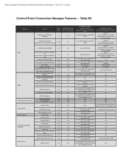
... Details Status Logs Diagnostics Connection base/ Hardware based Troubleshooting FAQ's/Web links SSO Pre-logon (Windows XP only) Log-on Ethernet WLAN View availabe networks & Site Monitors WiFi - Table B4 Category Feature Dell Wireless LAN 1397, 1510 (Broadcom) Dell Wireless LAN 1520 (Broadcom TGV - No for XP Yes for XP Yes - Dell Latitude E-Family & Mobile Precision...
... Details Status Logs Diagnostics Connection base/ Hardware based Troubleshooting FAQ's/Web links SSO Pre-logon (Windows XP only) Log-on Ethernet WLAN View availabe networks & Site Monitors WiFi - Table B4 Category Feature Dell Wireless LAN 1397, 1510 (Broadcom) Dell Wireless LAN 1520 (Broadcom TGV - No for XP Yes for XP Yes - Dell Latitude E-Family & Mobile Precision...

Owners Manual
Page 41
Connect the WiFi-switch board cable to secure the WiFi-switch board. 3. Follow the procedures in After Working Inside Your Computer. Fix the adhesive tape on the back of the system board. 41 Remove: a) battery b)... heat sink k) processor l) palmrest m) ExpressCard cage 3. Tighten the screw to the system board. 4. Removing the System Board 1. Installing the WiFi-Switch Board 1. Disconnect the power-connector cable from the bottom side of the WiFi-switch board and place the board in its slot. 2. Install: a) palmrest b) keyboard c) keyboard trim d) optical drive e) hard drive...
Connect the WiFi-switch board cable to secure the WiFi-switch board. 3. Follow the procedures in After Working Inside Your Computer. Fix the adhesive tape on the back of the system board. 41 Remove: a) battery b)... heat sink k) processor l) palmrest m) ExpressCard cage 3. Tighten the screw to the system board. 4. Removing the System Board 1. Installing the WiFi-Switch Board 1. Disconnect the power-connector cable from the bottom side of the WiFi-switch board and place the board in its slot. 2. Install: a) palmrest b) keyboard c) keyboard trim d) optical drive e) hard drive...

Owners Manual
Page 44
... 7. Install the LVDS support bracket in its position in the computer. 6. Lift the system board from the ports and connectors. 14. Installing the System Board 1. Connect the following cables to the computer. 3. Tighten the screws to secure the system board to the system board...
... 7. Install the LVDS support bracket in its position in the computer. 6. Lift the system board from the ports and connectors. 14. Installing the System Board 1. Connect the following cables to the computer. 3. Tighten the screws to secure the system board to the system board...


