User Manual
Page 1
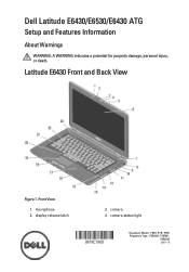
display release latch 3. camera status light Regulatory Model: : P25G, P19F, P25G Regulatory Type: : P25G001, P19F001, P25G002 2011 - 9 Front View 1. microphone 2. Dell Latitude E6430/E6530/E6430 ATG Setup and Features Information About Warnings WARNING: A WARNING indicates a potential for property damage, personal injury, or death. Latitude E6430 Front and Back View Figure 1. camera 4.
display release latch 3. camera status light Regulatory Model: : P25G, P19F, P25G Regulatory Type: : P25G001, P19F001, P25G002 2011 - 9 Front View 1. microphone 2. Dell Latitude E6430/E6530/E6430 ATG Setup and Features Information About Warnings WARNING: A WARNING indicates a potential for property damage, personal injury, or death. Latitude E6430 Front and Back View Figure 1. camera 4.
User Manual
Page 3
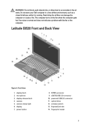
Do not store your Dell computer in the air vents. The computer turns on the fan when the computer gets hot. Latitude E6530 Front and Back View Figure 3. power button 8. fingerprint reader 3 display latch 2. display 7. HDMI connector 9. Front View 1. powered USB 3.0 connector 11. microphone 3. optical drive 12. Fan noise is running. display release latch 4. camera...
Do not store your Dell computer in the air vents. The computer turns on the fan when the computer gets hot. Latitude E6530 Front and Back View Figure 3. power button 8. fingerprint reader 3 display latch 2. display 7. HDMI connector 9. Front View 1. powered USB 3.0 connector 11. microphone 3. optical drive 12. Fan noise is running. display release latch 4. camera...
User Manual
Page 5
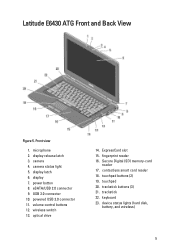
.... trackstick 22. display latch 6. wireless switch 13. touchpad 20. power button 8. optical drive 14. Secure Digital (SD) memory-card reader 17. trackstick buttons (3) 21. display release latch 3. Latitude E6430 ATG Front and Back View Figure 5. powered USB 3.0 connector 11. fingerprint reader 16.
.... trackstick 22. display latch 6. wireless switch 13. touchpad 20. power button 8. optical drive 14. Secure Digital (SD) memory-card reader 17. trackstick buttons (3) 21. display release latch 3. Latitude E6430 ATG Front and Back View Figure 5. powered USB 3.0 connector 11. fingerprint reader 16.
User Manual
Page 6
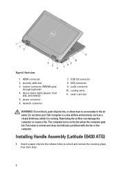
... not block, push objects into the release holes to accumulate in a low-airflow environment, such as a closed briefcase, while it is normal and does not indicate a problem with the fan or the computer. Do not store your Dell computer in the air vents. Installing Handle Assembly (Latitude E6430 ATG) 1. security cable slot 3. power...
... not block, push objects into the release holes to accumulate in a low-airflow environment, such as a closed briefcase, while it is normal and does not indicate a problem with the fan or the computer. Do not store your Dell computer in the air vents. Installing Handle Assembly (Latitude E6430 ATG) 1. security cable slot 3. power...
Latitude E-Family Re-Imaging Guide
Page 10
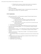
...; DCP Extended Battery Life - Reader, Flash, and ARM - 1st & 2nd generations Latitude EFamily & Mobile Precision 1. Intel® Smart Connect Technology Dell Latitude E-Family & Mobile Precision Reimage "How-To" Guide HW based solution using ...Latitude E-Family & Mobile Precision o Dell Data Protection | Access - 3rd & 4th generations Latitude E-Family & Mobile Precision o Dell Data Protection | Encryption - 3rd & 4th generations Latitude E-Family & Mobile Precision o Latitude On / Precision On - EBL Requires Dell DCP System Manager (for all System Manager release...
...; DCP Extended Battery Life - Reader, Flash, and ARM - 1st & 2nd generations Latitude EFamily & Mobile Precision 1. Intel® Smart Connect Technology Dell Latitude E-Family & Mobile Precision Reimage "How-To" Guide HW based solution using ...Latitude E-Family & Mobile Precision o Dell Data Protection | Access - 3rd & 4th generations Latitude E-Family & Mobile Precision o Dell Data Protection | Encryption - 3rd & 4th generations Latitude E-Family & Mobile Precision o Latitude On / Precision On - EBL Requires Dell DCP System Manager (for all System Manager release...
Latitude E-Family Re-Imaging Guide
Page 25
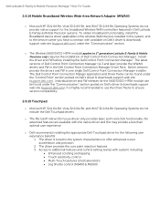
Individual driver and FW releases for the 5600 EVDO-HPSA module can be found under the "Control Point" section posted on Dell's driver & downloads support web site (support.dell.com). No advanced features are available with system) including: Enhanced scrolling and tapping ...the native driver and this may provide a less than optimal user experience o Dell recommends installing the appropriate Dell Touchpad driver for the broadband Wireless WAN controllers featured in Dell Latitude E-Family & Mobile Precision systems. To obtain broadband functionality, install the Broadband ...
Individual driver and FW releases for the 5600 EVDO-HPSA module can be found under the "Control Point" section posted on Dell's driver & downloads support web site (support.dell.com). No advanced features are available with system) including: Enhanced scrolling and tapping ...the native driver and this may provide a less than optimal user experience o Dell recommends installing the appropriate Dell Touchpad driver for the broadband Wireless WAN controllers featured in Dell Latitude E-Family & Mobile Precision systems. To obtain broadband functionality, install the Broadband ...

Latitude E-Family Re-Imaging Guide
Page 40
What is eSATA? a. Alternatively, end users can interface with the systems software released by Dell 8. What is the Client System Update application? eSATA is found under System Management...designed to allow users to manage systems on the system is a dual eSATA / USB combo port. The Dell System Software utility provides critical updates and patches for your operating system necessary for the correct operation of the ... o Up to 2 meter shielded cables and connectors It is an industry standard interface. Dell Latitude E-Family & Mobile Precision Reimage "How-To" Guide a.
What is eSATA? a. Alternatively, end users can interface with the systems software released by Dell 8. What is the Client System Update application? eSATA is found under System Management...designed to allow users to manage systems on the system is a dual eSATA / USB combo port. The Dell System Software utility provides critical updates and patches for your operating system necessary for the correct operation of the ... o Up to 2 meter shielded cables and connectors It is an industry standard interface. Dell Latitude E-Family & Mobile Precision Reimage "How-To" Guide a.
Latitude E-Family Re-Imaging Guide
Page 41
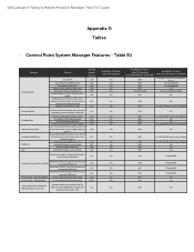
... color settings (certain panels only) v1.3 Availablity of Feature when only Windows OS installed? Yes, through BIOS Yes, through on screen display DCP SM Release Version v1.0 v1.0 v1.0 v1.0 v1.0 v1.0 v1.4 v1.3 v1.0 v1.0 v1.0 v1.0 v1.0 v1.0 v1.0 v1.0 v1.0 v1...Hot Key customizaton Keyboard backlighting Brightness ALS Feature user profiles View battery manufacturer info. Discreet Graphics Fn+E to toggle display by default). Dell Latitude E-Family & Mobile Precision Reimage "How-To" Guide Appendix D Tables - Keyboard backlighting options (to be able to set to enable/disable...
... color settings (certain panels only) v1.3 Availablity of Feature when only Windows OS installed? Yes, through BIOS Yes, through on screen display DCP SM Release Version v1.0 v1.0 v1.0 v1.0 v1.0 v1.0 v1.4 v1.3 v1.0 v1.0 v1.0 v1.0 v1.0 v1.0 v1.0 v1.0 v1.0 v1...Hot Key customizaton Keyboard backlighting Brightness ALS Feature user profiles View battery manufacturer info. Discreet Graphics Fn+E to toggle display by default). Dell Latitude E-Family & Mobile Precision Reimage "How-To" Guide Appendix D Tables - Keyboard backlighting options (to be able to set to enable/disable...
Latitude E-Family Re-Imaging Guide
Page 42
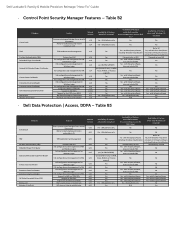
Dell Latitude E-Family & Mobile Precision Reimage "How-To" Guide - No Availabilty of Feature when DDPA Installed? USH platforms only Yes Yes - with 3rd party software Yes - with ... Print Reader Contact Smart Card Reader Contacless Smart Card Reader Contacless Smart Card Reader Full Disked Encrypted Drives (FDE) RSA SecurID Bitlocker (Vista Only) Feature Release Version Secure processing and storage of user security information v2.0 Ability to locally backup and restore credentials in CV v1.4 TPM enablement and management v1...
Dell Latitude E-Family & Mobile Precision Reimage "How-To" Guide - No Availabilty of Feature when DDPA Installed? USH platforms only Yes Yes - with 3rd party software Yes - with ... Print Reader Contact Smart Card Reader Contacless Smart Card Reader Contacless Smart Card Reader Full Disked Encrypted Drives (FDE) RSA SecurID Bitlocker (Vista Only) Feature Release Version Secure processing and storage of user security information v2.0 Ability to locally backup and restore credentials in CV v1.4 TPM enablement and management v1...
Latitude E-Family Re-Imaging Guide
Page 43
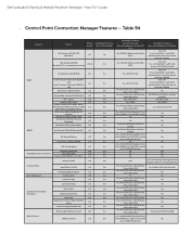
...• Intel® Centrino® Ultimate-N 6300 WiFi card • Intel® Centrino® Advanced-N 6200 WiFi card Disconnect on Features VPN Enforcement Release Version v1.1 v1.3.01 v1.2 v1.4 v1.2 v1.0 v1.0 v1.0 v1.2 v1.0 v1.2 v1.0 v1.4 v1.4 v1.0 v1.0 v1.0 v1.0...Hardware based Troubleshooting FAQ's/Web links SSO Pre-logon (Windows XP only) Log-on Ethernet WLAN View availabe networks & Site Monitors WiFi - Dell Latitude E-Family & Mobile Precision Reimage "How-To" Guide - Control Point Connection Manager Features - Availablity of Feature when only Windows OS installed?...
...• Intel® Centrino® Ultimate-N 6300 WiFi card • Intel® Centrino® Advanced-N 6200 WiFi card Disconnect on Features VPN Enforcement Release Version v1.1 v1.3.01 v1.2 v1.4 v1.2 v1.0 v1.0 v1.0 v1.2 v1.0 v1.2 v1.0 v1.4 v1.4 v1.0 v1.0 v1.0 v1.0...Hardware based Troubleshooting FAQ's/Web links SSO Pre-logon (Windows XP only) Log-on Ethernet WLAN View availabe networks & Site Monitors WiFi - Dell Latitude E-Family & Mobile Precision Reimage "How-To" Guide - Control Point Connection Manager Features - Availablity of Feature when only Windows OS installed?...

Owners Manual
Page 11
... computer. Slide the SD card into place. 2. Follow the procedures in After Working Inside Your Computer. 11 Recommended Tools The procedures in on how to release it clicks into its slot until it from your computer. Installing the Secure Digital (SD) Card 1. 2 Removing and Installing Components This section provides detailed information...
... computer. Slide the SD card into place. 2. Follow the procedures in After Working Inside Your Computer. 11 Recommended Tools The procedures in on how to release it clicks into its slot until it from your computer. Installing the Secure Digital (SD) Card 1. 2 Removing and Installing Components This section provides detailed information...

Owners Manual
Page 12
Follow the procedures in After Working Inside Your Computer. Installing the ExpressCard 1. Slide the ExpressCard out of the computer. 12 Removing the Battery 1. Removing the ExpressCard 1. Press in Before Working Inside Your Computer. 2. Follow the procedures in Before Working Inside Your Computer. 2. Slide the ExpressCard into its slot until it from the computer. 3. Follow the procedures in on the ExpressCard to unlock the battery and flip the battery out of the computer. Slide the release latches to release it clicks into place. 2.
Follow the procedures in After Working Inside Your Computer. Installing the ExpressCard 1. Slide the ExpressCard out of the computer. 12 Removing the Battery 1. Removing the ExpressCard 1. Press in Before Working Inside Your Computer. 2. Follow the procedures in Before Working Inside Your Computer. 2. Slide the ExpressCard into its slot until it from the computer. 3. Follow the procedures in on the ExpressCard to unlock the battery and flip the battery out of the computer. Slide the release latches to release it clicks into place. 2.

Owners Manual
Page 14
3. Installing the Base Cover 1. Install the battery. 4. Follow the procedures in After Working Inside Your Computer. Using a plastic scribe, pry under the keyboard trim to remove it from the computer. Lift the base cover to release it from the computer. 4. Removing the Keyboard Trim 1. Remove the battery. 3. Place the base cover to the computer. 3. Pry the keyboard trim along the sides and bottom. 14 Follow the procedures in Before Working Inside Your Computer. 2. Tighten the screws to secure the base cover to align with the screw holes on the computer. 2.
3. Installing the Base Cover 1. Install the battery. 4. Follow the procedures in After Working Inside Your Computer. Using a plastic scribe, pry under the keyboard trim to remove it from the computer. Lift the base cover to release it from the computer. 4. Removing the Keyboard Trim 1. Remove the battery. 3. Place the base cover to the computer. 3. Pry the keyboard trim along the sides and bottom. 14 Follow the procedures in Before Working Inside Your Computer. 2. Tighten the screws to secure the base cover to align with the screw holes on the computer. 2.

Owners Manual
Page 19
... optical-drive latch to the hard drive. 4. Attach the hard-drive caddy to the computer. 6. Tighten the screws to secure the hard-drive caddy to release the optical drive from the computer. 19 Remove the battery. 3. Follow the procedures in Before Working Inside Your Computer. 2. Removing the Optical Drive 1. Install the...
... optical-drive latch to the hard drive. 4. Attach the hard-drive caddy to the computer. 6. Tighten the screws to secure the hard-drive caddy to release the optical drive from the computer. 19 Remove the battery. 3. Follow the procedures in Before Working Inside Your Computer. 2. Removing the Optical Drive 1. Install the...

Owners Manual
Page 28
Installing the Modem Card 1. Connect the modem cable to secure the modem card. 5. Tighten the screw to the modem card. 4. Lift the modem card to ensure that the tab on the back of the card is engaged. 3. 4. Install: a) base cover b) battery 6. Insert the modem card in After Working Inside Your Computer. 28 Seat the modem card, to release the tab from the computer. Grasp the modem card and remove the it from the connector on the back of the card. 5. Follow the procedures in its slot 2. Disconnect the modem cable from the modem card. 6.
Installing the Modem Card 1. Connect the modem cable to secure the modem card. 5. Tighten the screw to the modem card. 4. Lift the modem card to ensure that the tab on the back of the card is engaged. 3. 4. Install: a) base cover b) battery 6. Insert the modem card in After Working Inside Your Computer. 28 Seat the modem card, to release the tab from the computer. Grasp the modem card and remove the it from the connector on the back of the card. 5. Follow the procedures in its slot 2. Disconnect the modem cable from the modem card. 6.

Owners Manual
Page 44
Release the system board from the computer. Lift the system board from the ports and connectors. 14. Tighten the screws to secure the LVDS support bracket ...
Release the system board from the computer. Lift the system board from the ports and connectors. 14. Tighten the screws to secure the LVDS support bracket ...

Owners Manual
Page 49
... computer. 49 Route the antenna and the LVDS cables through the opening of the computer. 10. Tighten the screw to secure the support bracket to release the display assembly on both sides. 9. 8. Lift the display assembly and pull the LVDS and the antenna cables through the routing channel. 5. Place the display...
... computer. 49 Route the antenna and the LVDS cables through the opening of the computer. 10. Tighten the screw to secure the support bracket to release the display assembly on both sides. 9. 8. Lift the display assembly and pull the LVDS and the antenna cables through the routing channel. 5. Place the display...

Owners Manual
Page 54
8. Remove the display assembly from the computer. Installing the Display Assembly 1. Tighten the screws on both corners to release the display assembly on both sides. 9. Remove the screws to secure the display assembly. 4. Tighten the screw to secure the support bracket to the computer: a) ...
8. Remove the display assembly from the computer. Installing the Display Assembly 1. Tighten the screws on both corners to release the display assembly on both sides. 9. Remove the screws to secure the display assembly. 4. Tighten the screw to secure the support bracket to the computer: a) ...


