User Manual
Page 1
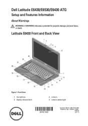
Front View 1. Latitude E6430 Front and Back View Figure 1. display release latch 3. camera status light Regulatory Model: : P25G, P19F, P25G Regulatory Type: : P25G001, P19F001, P25G002 2011 - 9 camera 4. microphone 2. Dell Latitude E6430/E6530/E6430 ATG Setup and Features Information About Warnings WARNING: A WARNING indicates a potential for property damage, personal injury, or death.
Front View 1. Latitude E6430 Front and Back View Figure 1. display release latch 3. camera status light Regulatory Model: : P25G, P19F, P25G Regulatory Type: : P25G001, P19F001, P25G002 2011 - 9 camera 4. microphone 2. Dell Latitude E6430/E6530/E6430 ATG Setup and Features Information About Warnings WARNING: A WARNING indicates a potential for property damage, personal injury, or death.
User Manual
Page 3
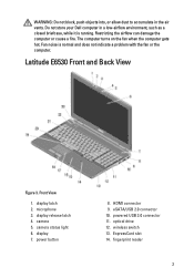
Do not store your Dell computer in the air vents. Latitude E6530 Front and Back View Figure 3. display 7. powered USB 3.0 connector 11. optical drive 12. Fan noise is running. The computer turns on the fan when ... to accumulate in a low-airflow environment, such as a closed briefcase, while it is normal and does not indicate a problem with the fan or the computer. camera 5. fingerprint reader 3 HDMI connector 9. ExpressCard slot 14. Front View 1. camera status light 6. display release latch 4. Restricting the airflow can damage the computer or cause a fire.
Do not store your Dell computer in the air vents. Latitude E6530 Front and Back View Figure 3. display 7. powered USB 3.0 connector 11. optical drive 12. Fan noise is running. The computer turns on the fan when ... to accumulate in a low-airflow environment, such as a closed briefcase, while it is normal and does not indicate a problem with the fan or the computer. camera 5. fingerprint reader 3 HDMI connector 9. ExpressCard slot 14. Front View 1. camera status light 6. display release latch 4. Restricting the airflow can damage the computer or cause a fire.
User Manual
Page 5
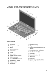
Latitude E6430 ATG Front and Back View Figure 5. display 7. USB 3.0 connector 10. wireless switch 13. Secure Digital (SD) memory-card reader 17. powered USB 3.0 connector 11. power button 8. touchpad buttons (2) 19. device status lights (hard disk, battery, and wireless) 5 camera 4. contactless smart card reader 18. display latch 6. eSATA/USB 2.0 connector 9. touchpad 20. fingerprint reader...
Latitude E6430 ATG Front and Back View Figure 5. display 7. USB 3.0 connector 10. wireless switch 13. Secure Digital (SD) memory-card reader 17. powered USB 3.0 connector 11. power button 8. touchpad buttons (2) 19. device status lights (hard disk, battery, and wireless) 5 camera 4. contactless smart card reader 18. display latch 6. eSATA/USB 2.0 connector 9. touchpad 20. fingerprint reader...

Owner's Manual
Page 4
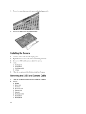
......50 Removing the Display-Hinge Caps...50 Installing the Display-Hinge Caps...51 Removing the Display Hinges...52 Installing the Display Hinges...53 Removing the Camera...53 Installing the Camera...54 Removing the LVDS and Camera Cable...54 Installing the LVDS and Camera Cable...55 Removing the Speakers...56 Installing the Speakers...57
......50 Removing the Display-Hinge Caps...50 Installing the Display-Hinge Caps...51 Removing the Display Hinges...52 Installing the Display Hinges...53 Removing the Camera...53 Installing the Camera...54 Removing the LVDS and Camera Cable...54 Installing the LVDS and Camera Cable...55 Removing the Speakers...56 Installing the Speakers...57
Owner's Manual
Page 42
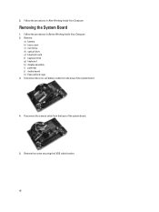
Removing the System Board 1. Remove: a) battery b) base cover c) hard drive d) optical drive e) bluetooth card f) keyboard trim g) keyboard h) display assembly i) palmrest j) media board k) ExpressCard cage 3. 5. Follow the procedures in Before Working Inside Your Computer. 2. Disconnect the coin-cell battery cable from the base of the system board. 4. Remove the screw securing the LVDS cable bracket. 42 Follow the procedures in After Working Inside Your Computer. Disconnect the camera cable from the base of the system board. 5.
Removing the System Board 1. Remove: a) battery b) base cover c) hard drive d) optical drive e) bluetooth card f) keyboard trim g) keyboard h) display assembly i) palmrest j) media board k) ExpressCard cage 3. 5. Follow the procedures in Before Working Inside Your Computer. 2. Disconnect the coin-cell battery cable from the base of the system board. 4. Remove the screw securing the LVDS cable bracket. 42 Follow the procedures in After Working Inside Your Computer. Disconnect the camera cable from the base of the system board. 5.
Owner's Manual
Page 46
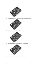
Remove the LVDS and camera cable from the computer. 7. 5. Disconnect the camera cable from the routing channel. 8. Disconnect any antennas connected to disconnect the LVDS cable from the computer. 6. Pull upwards on the tab to wireless solutions. 46
Remove the LVDS and camera cable from the computer. 7. 5. Disconnect the camera cable from the routing channel. 8. Disconnect any antennas connected to disconnect the LVDS cable from the computer. 6. Pull upwards on the tab to wireless solutions. 46
Owner's Manual
Page 48
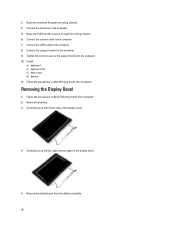
...Tighten the screw to secure the support bracket to the computer. 5. Remove the display bezel from the display assembly. 48 Connect the camera cable to the computer. 9. Follow the procedures in After Working Inside Your Computer. Remove the battery. 3. Removing the Display Bezel...a) keyboard b) keyboard trim c) base cover d) battery 11. Follow the procedures in Before Working Inside Your Computer. 2. Route the LVDS and the camera through the routing channel. 4. Connect the support bracket to the computer. 7. Carefully pry up the left, right and top edges of the display ...
...Tighten the screw to secure the support bracket to the computer. 5. Remove the display bezel from the display assembly. 48 Connect the camera cable to the computer. 9. Follow the procedures in After Working Inside Your Computer. Remove the battery. 3. Removing the Display Bezel...a) keyboard b) keyboard trim c) base cover d) battery 11. Follow the procedures in Before Working Inside Your Computer. 2. Route the LVDS and the camera through the routing channel. 4. Connect the support bracket to the computer. 7. Carefully pry up the left, right and top edges of the display ...
Owner's Manual
Page 53
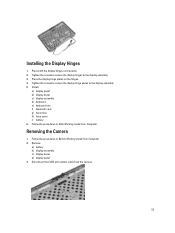
... assembly c) display bezel d) display panel 3. Tighten the screws to secure the display hinges to the display assembly. 5. Removing the Camera 1. Tighten the screws to secure the display hinge plates to the display assembly. 3. Follow the procedures in Before Working Inside Your ...Computer. 2. Disconnect the LVDS and camera cable from the camera. 53 Install: a) display panel b) display bezel c) display assembly d) keyboard e) keyboard trim f) bluetooth card g) hard drive h)...
... assembly c) display bezel d) display panel 3. Tighten the screws to secure the display hinges to the display assembly. 5. Removing the Camera 1. Tighten the screws to secure the display hinge plates to the display assembly. 3. Follow the procedures in Before Working Inside Your ...Computer. 2. Disconnect the LVDS and camera cable from the camera. 53 Install: a) display panel b) display bezel c) display assembly d) keyboard e) keyboard trim f) bluetooth card g) hard drive h)...
Owner's Manual
Page 54
... on the display panel. 2. Install: a) display panel b) display bezel c) display assembly d) battery 5. Remove the screw that secures the camera to the display assembly. 5. Install the camera in After Working Inside Your Computer. Remove the camera from the display assembly. Remove: a) battery b) base cover c) hard drive d) bluetooth card e) keyboard trim f) keyboard g) display assembly h) display...
... on the display panel. 2. Install: a) display panel b) display bezel c) display assembly d) battery 5. Remove the screw that secures the camera to the display assembly. 5. Install the camera in After Working Inside Your Computer. Remove the camera from the display assembly. Remove: a) battery b) base cover c) hard drive d) bluetooth card e) keyboard trim f) keyboard g) display assembly h) display...

Owner's Manual
Page 55
Connect the LVDS and camera cable to secure the cable. 3. Installing the LVDS and Camera Cable 1. Install: a) display hinges b) display panel c) display bezel d) display assembly e) keyboard f) keyboard trim g) bluetooth card 55 Fix the adhesive the tape to the camera. 4. Route the LVDS and camera cable on the display assembly. 2. Remove the LVDS and camera cable from the camera. 4. j) display hinges 3. Peel back the adhesives securing the LVDS and camera cable to the display assembly. 5. Disconnect the LVDS and camera cable from the display assembly.
Connect the LVDS and camera cable to secure the cable. 3. Installing the LVDS and Camera Cable 1. Install: a) display hinges b) display panel c) display bezel d) display assembly e) keyboard f) keyboard trim g) bluetooth card 55 Fix the adhesive the tape to the camera. 4. Route the LVDS and camera cable on the display assembly. 2. Remove the LVDS and camera cable from the camera. 4. j) display hinges 3. Peel back the adhesives securing the LVDS and camera cable to the display assembly. 5. Disconnect the LVDS and camera cable from the display assembly.

Owner's Manual
Page 64
... Internal Modem • Enable Microphone • Enable eSATA Ports • Enable Hard Drive Free Fall Protection • Enable Module Bay • Enable ExpressCard • Enable Camera • Enable Media Card • Disable Media Card Default Setting: All devices are enabled. Allows you enable or disable the various on board devices. The...
... Internal Modem • Enable Microphone • Enable eSATA Ports • Enable Hard Drive Free Fall Protection • Enable Module Bay • Enable ExpressCard • Enable Camera • Enable Media Card • Disable Media Card Default Setting: All devices are enabled. Allows you enable or disable the various on board devices. The...
Latitude E-Family Re-Imaging Guide
Page 28
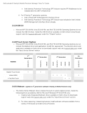
... 3rd Generation 4th Generation E6400 ATG E6410 ATG M6500 E6420 E6420 ATG E6520 M4600 M6600 E6430 ATG Digitech Touch Screen X X eGalax EMPIA X X X X X n-Trig Multi Touch X X 2.6.21 Webcam -applies to be installed after the AMT Unified driver 4. Dell Latitude E-Family & Mobile Precision Reimage "How-To" Guide Intel Identity Protection Technology (IPT) feature ...3.0 driver. For E-Family 4th generation systems, Intel Unified AMT 8 Management Interface Driver Intel Identity Protection Technology (IPT) feature was included in system digital camera.
... 3rd Generation 4th Generation E6400 ATG E6410 ATG M6500 E6420 E6420 ATG E6520 M4600 M6600 E6430 ATG Digitech Touch Screen X X eGalax EMPIA X X X X X n-Trig Multi Touch X X 2.6.21 Webcam -applies to be installed after the AMT Unified driver 4. Dell Latitude E-Family & Mobile Precision Reimage "How-To" Guide Intel Identity Protection Technology (IPT) feature ...3.0 driver. For E-Family 4th generation systems, Intel Unified AMT 8 Management Interface Driver Intel Identity Protection Technology (IPT) feature was included in system digital camera.


