Service Manual
Page 4
Dell™ Latitude™ E6400 XFR Service Manual 9.2 REPLACING THE RF PASSTHRU BOARD ...31 10 FAN ASSEMBLY ...32 10.1 REMOVING THE FAN ASSEMBLY ...32 10.2 REPLACING THE FAN ASSEMBLY ...33 11 ... 14 COIN-CELL BATTERY ...38 14.1 REMOVING THE COIN-CELL BATTERY ...38 14.2 REPLACING THE COIN-CELL BATTERY...38 15 LED COVER ...39 15.1 REMOVING THE LED COVER ...39 15.2 REPLACING THE LED COVER ...40 16 PALM REST OVERLAY ...40 16.1 REMOVING THE PALM REST OVERLAY ...40 16.2 REPLACING THE PALM REST OVERLAY...
Dell™ Latitude™ E6400 XFR Service Manual 9.2 REPLACING THE RF PASSTHRU BOARD ...31 10 FAN ASSEMBLY ...32 10.1 REMOVING THE FAN ASSEMBLY ...32 10.2 REPLACING THE FAN ASSEMBLY ...33 11 ... 14 COIN-CELL BATTERY ...38 14.1 REMOVING THE COIN-CELL BATTERY ...38 14.2 REPLACING THE COIN-CELL BATTERY...38 15 LED COVER ...39 15.1 REMOVING THE LED COVER ...39 15.2 REPLACING THE LED COVER ...40 16 PALM REST OVERLAY ...40 16.1 REMOVING THE PALM REST OVERLAY ...40 16.2 REPLACING THE PALM REST OVERLAY...
Service Manual
Page 39
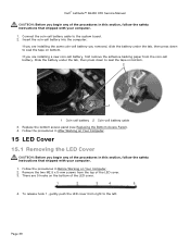
Dell™ Latitude™ E6400 XFR Service Manual CAUTION: Before you begin any of the procedures in this section, follow the safety instructions that shipped with your computer. 1. Slide the battery under the tab, then press down to seal the tape on Your Computer. 2. Follow the procedures in After Working on Your Computer. 15 LED...cell battery, first remove the adhesive backing paper from right to the system board. 2. To release hook 1, gently push the LED cover from the coin-cell battery. Connect the coin-cell battery cable to the left. Insert the coin-cell battery into ...
Dell™ Latitude™ E6400 XFR Service Manual CAUTION: Before you begin any of the procedures in this section, follow the safety instructions that shipped with your computer. 1. Slide the battery under the tab, then press down to seal the tape on Your Computer. 2. Follow the procedures in After Working on Your Computer. 15 LED...cell battery, first remove the adhesive backing paper from right to the system board. 2. To release hook 1, gently push the LED cover from the coin-cell battery. Connect the coin-cell battery cable to the left. Insert the coin-cell battery into ...

Service Manual
Page 40
...on the assembly, then rotating the back edge slightly while prying with the plastic scribe. 15.2 Replacing the LED Cover CAUTION: Before you begin any of the LED cover. 2 3 1 1 Scribe 2 LED cover 3 M2.5 x 5-mm screw (2) 6. Starting from the middle of the procedures in After Working on... any of the palm rest overlay, carefully peel the overlay away from the base. Page 40 Dell™ Latitude™ E6400 XFR Service Manual 5. While still applying pressure to secure the LED cover. 3. Working at an angle, snap the LED cover into place one hook at a time. 2.
...on the assembly, then rotating the back edge slightly while prying with the plastic scribe. 15.2 Replacing the LED Cover CAUTION: Before you begin any of the LED cover. 2 3 1 1 Scribe 2 LED cover 3 M2.5 x 5-mm screw (2) 6. Starting from the middle of the procedures in After Working on... any of the palm rest overlay, carefully peel the overlay away from the base. Page 40 Dell™ Latitude™ E6400 XFR Service Manual 5. While still applying pressure to secure the LED cover. 3. Working at an angle, snap the LED cover into place one hook at a time. 2.
Service Manual
Page 41
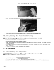
... instructions that it stays in After Working on Your Computer. 2. Remove the palm rest overlay (see Removing the LED Cover). 3. Working your way from middle to left . 4. After the middle is properly aligned. 3. Follow... of the procedures in this section, follow the safety instructions that shipped with your computer. 1. Remove the LED cover (see Removing the Palm Rest Overlay). 4. Follow the procedures in Before Working on Your Computer. 17... place and ensure that shipped with your computer. 1. Dell™ Latitude™ E6400 XFR Service Manual 3. Page 41
... instructions that it stays in After Working on Your Computer. 2. Remove the palm rest overlay (see Removing the LED Cover). 3. Working your way from middle to left . 4. After the middle is properly aligned. 3. Follow... of the procedures in this section, follow the safety instructions that shipped with your computer. 1. Remove the LED cover (see Removing the Palm Rest Overlay). 4. Follow the procedures in Before Working on Your Computer. 17... place and ensure that shipped with your computer. 1. Dell™ Latitude™ E6400 XFR Service Manual 3. Page 41
Service Manual
Page 42
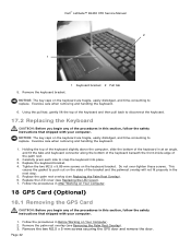
... you begin any of the bracket and the palmrest overlay will not fit properly in Before Working on Your Computer. 2. Replace the LED cover (see Replacing the LED Cover). 7. Dell™ Latitude™ E6400 XFR Service Manual 2 1 5. NOTICE: The key caps on Your Computer. 18 GPS Card (Optional) 18.1 Removing the GPS Card CAUTION: Before you...
... you begin any of the bracket and the palmrest overlay will not fit properly in Before Working on Your Computer. 2. Replace the LED cover (see Replacing the LED Cover). 7. Dell™ Latitude™ E6400 XFR Service Manual 2 1 5. NOTICE: The key caps on Your Computer. 18 GPS Card (Optional) 18.1 Removing the GPS Card CAUTION: Before you...
Service Manual
Page 49
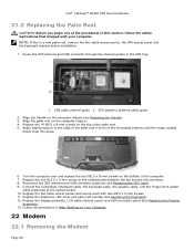
Align the palm rest on the motherboard between the fan and the fan connector. 8. Replace the keyboard, LED cover and palm rest overlay (see Replacing the Handle). 3. Align the handle on the top of the procedures in After Working on the bottom ... that shipped with two M2.5 x 5-mm screws. 11. Replace the 16 M2.5 x 8-mm screws on the computer chassis (see Replacing the Keyboard). 12. Dell™ Latitude™ E6400 XFR Service Manual 21.2 Replacing the Palm Rest CAUTION: Before you begin any of the palm rest. 5. Connect the contactless smartcard cable, the touchpad cable...
Align the palm rest on the motherboard between the fan and the fan connector. 8. Replace the keyboard, LED cover and palm rest overlay (see Replacing the Handle). 3. Align the handle on the top of the procedures in After Working on the bottom ... that shipped with two M2.5 x 5-mm screws. 11. Replace the 16 M2.5 x 8-mm screws on the computer chassis (see Replacing the Keyboard). 12. Dell™ Latitude™ E6400 XFR Service Manual 21.2 Replacing the Palm Rest CAUTION: Before you begin any of the palm rest. 5. Connect the contactless smartcard cable, the touchpad cable...
Service Manual
Page 50
...modem. 2. Follow the procedures in Before Working on Your Computer. Follow the procedures in Before Working on Your Computer. 2. Dell™ Latitude™ E6400 XFR Service Manual CAUTION: Before you begin any of the procedures in this section, follow the safety instructions that shipped with your computer... I /O card. 3. Use the screw hole on the modem to the I /O card. 5. Replace the palm rest, keyboard, palm rest overlay, LED cover, display assembly, LCD cable channel covers and bottom access panel (see Removing the Palm Rest). 3. Page 50 Connect the modem cable to the I...
...modem. 2. Follow the procedures in Before Working on Your Computer. Follow the procedures in Before Working on Your Computer. 2. Dell™ Latitude™ E6400 XFR Service Manual CAUTION: Before you begin any of the procedures in this section, follow the safety instructions that shipped with your computer... I /O card. 3. Use the screw hole on the modem to the I /O card. 5. Replace the palm rest, keyboard, palm rest overlay, LED cover, display assembly, LCD cable channel covers and bottom access panel (see Removing the Palm Rest). 3. Page 50 Connect the modem cable to the I...
Service Manual
Page 51
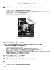
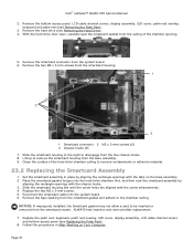
...Removing the Palm Rest). 3. Replace the two M2 x 3-mm screws. 5. Page 51 Dell™ Latitude™ E6400 XFR Service Manual 2. Remove the bottom access panel, LCD cable channel covers, display assembly, LED cover, palm rest overlay, keyboard and palm rest (see Removing the Hard Drive). 4. ...the hard drive door open, carefully peel the smartcard gasket from the base assembly. 9. Replace the palm rest, keyboard, palm rest overlay, LED cover, display assembly, LCD cable channel covers and bottom access panel (see Replacing the Palm Rest). 8. Remove the smartcard connector from the ...
...Removing the Palm Rest). 3. Replace the two M2 x 3-mm screws. 5. Page 51 Dell™ Latitude™ E6400 XFR Service Manual 2. Remove the bottom access panel, LCD cable channel covers, display assembly, LED cover, palm rest overlay, keyboard and palm rest (see Removing the Hard Drive). 4. ...the hard drive door open, carefully peel the smartcard gasket from the base assembly. 9. Replace the palm rest, keyboard, palm rest overlay, LED cover, display assembly, LCD cable channel covers and bottom access panel (see Replacing the Palm Rest). 8. Remove the smartcard connector from the ...
Service Manual
Page 54
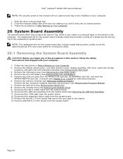
... position. 3. NOTE: The replacement kit for the system board also includes media that provides a utility to set the system board as XFR, and a tech sheet for the system board includes media that secure the card cage to the replacement system board. Follow the instructions ...13. Remove the bottom access panel, LCD cable channel covers, display assembly, LED cover, palm rest overlay, keyboard, and palm rest and smartcard assembly (see Removing the SIM Card Assembly). 11. Dell™ Latitude™ E6400 XFR Service Manual NOTE: The security screw on the modular drive is also visible on...
... position. 3. NOTE: The replacement kit for the system board also includes media that provides a utility to set the system board as XFR, and a tech sheet for the system board includes media that secure the card cage to the replacement system board. Follow the instructions ...13. Remove the bottom access panel, LCD cable channel covers, display assembly, LED cover, palm rest overlay, keyboard, and palm rest and smartcard assembly (see Removing the SIM Card Assembly). 11. Dell™ Latitude™ E6400 XFR Service Manual NOTE: The security screw on the modular drive is also visible on...
Service Manual
Page 56
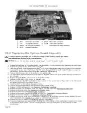
...system board into place and push down on the inside of the system board. 5. Replace the palm rest, keyboard, palm rest overlay and LED cover (see Replacing the Processor Module). 16. If you are installing a new system board, make a note of the number on the yellow...gasket for the multi-mode HD video connector is set properly, and the cable for the smartcard assembly is not interfering. 4. Page 56 Dell™ Latitude™ E6400 XFR Service Manual 1 JSC1 Smartcard connector 5 JBIO1 BIO reader connector 2 JTP1 Touchpad connector 6 J1394 1394 cable connector 3 JSNIF1 Wi-Fi sniffer ...
...system board into place and push down on the inside of the system board. 5. Replace the palm rest, keyboard, palm rest overlay and LED cover (see Replacing the Processor Module). 16. If you are installing a new system board, make a note of the number on the yellow...gasket for the multi-mode HD video connector is set properly, and the cable for the smartcard assembly is not interfering. 4. Page 56 Dell™ Latitude™ E6400 XFR Service Manual 1 JSC1 Smartcard connector 5 JBIO1 BIO reader connector 2 JTP1 Touchpad connector 6 J1394 1394 cable connector 3 JSNIF1 Wi-Fi sniffer ...

Service Manual
Page 59
... into position. 2. Remove the bottom access panel, LCD cable channel covers, display assembly, led cover, palm rest overlay, keyboard and palm rest (see Replacing the Card Cage). 4. Use the alignment planes to seat into position. Dell™ Latitude™ E6400 XFR Service Manual 28.2 Replacing the 1394 Card CAUTION: Before you begin any of the...
... into position. 2. Remove the bottom access panel, LCD cable channel covers, display assembly, led cover, palm rest overlay, keyboard and palm rest (see Replacing the Card Cage). 4. Use the alignment planes to seat into position. Dell™ Latitude™ E6400 XFR Service Manual 28.2 Replacing the 1394 Card CAUTION: Before you begin any of the...
Service Manual
Page 60
... x 5-mm screws that secure the card to motherboard 6. Remove the bottom access panel, LCD cable channel covers, display assembly, led cover, palm rest overlay, keyboard and palm rest (see Replacing the Palm Rest). 6. Replace the palm rest, keyboard, palm rest overlay..., led cover, display assembly, LCD cable channel covers and bottom access panel (see Removing the Palm Rest). 3. Follow the procedures in the battery bay. 4. Remove the M2 x 3-mm screw from the motherboard. 4. Dell™ Latitude™ E6400 XFR Service Manual 3. Install the Wi-Fi ...
... x 5-mm screws that secure the card to motherboard 6. Remove the bottom access panel, LCD cable channel covers, display assembly, led cover, palm rest overlay, keyboard and palm rest (see Replacing the Palm Rest). 6. Replace the palm rest, keyboard, palm rest overlay..., led cover, display assembly, LCD cable channel covers and bottom access panel (see Removing the Palm Rest). 3. Follow the procedures in the battery bay. 4. Remove the M2 x 3-mm screw from the motherboard. 4. Dell™ Latitude™ E6400 XFR Service Manual 3. Install the Wi-Fi ...

Service Manual
Page 61
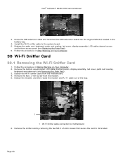
Replace the palm rest, keyboard, palm rest overlay, led cover, display assembly, LCD cable channel covers and bottom access panel (see Removing the System Board Assembly). 3. Remove the system board (see Replacing the Palm...Your Computer. 2. Remove the 2 M2.5 x 8-mm screws holding the sniffer card bracket, and remove the bracket. 2 1 Page 61 1 M2.5 x 5-mm screw 2 M2.5 x 8-mm screw (2) Dell™ Latitude™ E6400 XFR Service Manual 1 1 M2.5 x 5-mm screws (2) 30.2 Replacing the Wi-Fi Sniffer Card 1. Remove the sniffer card (see Replacing the Modem). 4. Follow the procedures in...
Replace the palm rest, keyboard, palm rest overlay, led cover, display assembly, LCD cable channel covers and bottom access panel (see Removing the System Board Assembly). 3. Remove the system board (see Replacing the Palm...Your Computer. 2. Remove the 2 M2.5 x 8-mm screws holding the sniffer card bracket, and remove the bracket. 2 1 Page 61 1 M2.5 x 5-mm screw 2 M2.5 x 8-mm screw (2) Dell™ Latitude™ E6400 XFR Service Manual 1 1 M2.5 x 5-mm screws (2) 30.2 Replacing the Wi-Fi Sniffer Card 1. Remove the sniffer card (see Replacing the Modem). 4. Follow the procedures in...

Service Manual
Page 62
...-11 modem connector into the base assembly, aligning the guides on Your Computer. Replace the palm rest, keyboard, palm rest overlay, led cover, display assembly, LCD cable channel covers and bottom access panel (see Replacing the Wi-Fi Sniffer Card). 4. Follow the procedure... on Your Computer. 2. Remove the bottom access panel, LCD cable channel covers, display assembly, led cover, palm rest overlay, keyboard and palm rest (see Replacing the Modem). 7. Dell™ Latitude™ E6400 XFR Service Manual 8. Replace the modem (see Removing the Palm Rest). 3. Remove the modem (see...
...-11 modem connector into the base assembly, aligning the guides on Your Computer. Replace the palm rest, keyboard, palm rest overlay, led cover, display assembly, LCD cable channel covers and bottom access panel (see Replacing the Wi-Fi Sniffer Card). 4. Follow the procedure... on Your Computer. 2. Remove the bottom access panel, LCD cable channel covers, display assembly, led cover, palm rest overlay, keyboard and palm rest (see Replacing the Modem). 7. Dell™ Latitude™ E6400 XFR Service Manual 8. Replace the modem (see Removing the Palm Rest). 3. Remove the modem (see...


