Service Manual
Page 4
Dell™ Latitude™ E6400 XFR Service Manual 9.2 REPLACING THE RF PASSTHRU BOARD ...31 10 FAN ASSEMBLY ...32 10.1 REMOVING THE FAN ASSEMBLY ...32 10.2 REPLACING THE FAN ASSEMBLY ...33 11 ... THE PALM REST OVERLAY ...41 17 KEYBOARD ...41 17.1 REMOVING THE KEYBOARD ...41 17.2 REPLACING THE KEYBOARD...42 18 GPS CARD (OPTIONAL) ...42 18.1 REMOVING THE GPS CARD...42 18.2 REPLACING THE GPS CARD ...42 19 LCD CABLE CHANNEL COVERS ...43 19.1 REMOVING THE LCD CABLE CHANNEL COVERS...43 19.2 REPLACING THE LCD...
Dell™ Latitude™ E6400 XFR Service Manual 9.2 REPLACING THE RF PASSTHRU BOARD ...31 10 FAN ASSEMBLY ...32 10.1 REMOVING THE FAN ASSEMBLY ...32 10.2 REPLACING THE FAN ASSEMBLY ...33 11 ... THE PALM REST OVERLAY ...41 17 KEYBOARD ...41 17.1 REMOVING THE KEYBOARD ...41 17.2 REPLACING THE KEYBOARD...42 18 GPS CARD (OPTIONAL) ...42 18.1 REMOVING THE GPS CARD...42 18.2 REPLACING THE GPS CARD ...42 19 LCD CABLE CHANNEL COVERS ...43 19.1 REMOVING THE LCD CABLE CHANNEL COVERS...43 19.2 REPLACING THE LCD...
Service Manual
Page 32
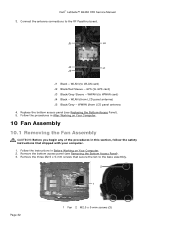
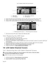
... Computer. 2. Connect the antenna connections to GPS card) J3 Black/Grey Sleeve - GPS (to the RF Passthru board. WWAN (to WWAN card) J4 Black - WWAN (from LCD panel antenna) J5 Black/Grey - Replace the bottom access panel (see Removing the Bottom Access Panel). 3. Dell™ Latitude™ E6400 XFR Service Manual 3. J5 J4 J2 J1 J3...
... Computer. 2. Connect the antenna connections to GPS card) J3 Black/Grey Sleeve - GPS (to the RF Passthru board. WWAN (to WWAN card) J4 Black - WWAN (from LCD panel antenna) J5 Black/Grey - Replace the bottom access panel (see Removing the Bottom Access Panel). 3. Dell™ Latitude™ E6400 XFR Service Manual 3. J5 J4 J2 J1 J3...
Service Manual
Page 42
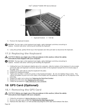
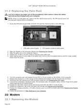
... Replacing the Palm Rest Overlay). 6. Replace the keyboard bracket. 4. Replace the palm rest overlay (see Replacing the LED Cover). 7. Page 42 Dell™ Latitude™ E6400 XFR Service Manual 2 1 5. Follow the procedures in the next step. 5. Exercise care when removing and handling the keyboard. 6. This causes the ... to snap the keyboard into place. 3. Do not over-tighten these screws. Remove the two M2.5 x 5-mm screws securing the GPS door and remove the door. Holding the top of the keyboard slightly above the computer, slide the bottom of the keyboard in at ...
... Replacing the Palm Rest Overlay). 6. Replace the keyboard bracket. 4. Replace the palm rest overlay (see Replacing the LED Cover). 7. Page 42 Dell™ Latitude™ E6400 XFR Service Manual 2 1 5. Follow the procedures in the next step. 5. Exercise care when removing and handling the keyboard. 6. This causes the ... to snap the keyboard into place. 3. Do not over-tighten these screws. Remove the two M2.5 x 5-mm screws securing the GPS door and remove the door. Holding the top of the keyboard slightly above the computer, slide the bottom of the keyboard in at ...
Service Manual
Page 43
...Channel Covers 19.1 Removing the LCD Cable Channel Covers CAUTION: Before you begin any of the Palm Rest. 3. Connect the GPS Passthru antenna (black antenna with your computer. Replace the palm rest overlay (see Replacing the Palm Rest Overlay). 8. Remove.... 1. Close the display and turn the computer upside down. 3. Using a scribe, gently detach the GPS card at the upper left corner of the card. 6. Follow the procedures in the GPS bay of the procedures in the antenna bay. 4. GPS Module 2. Dell™ Latitude™ E6400 XFR Service Manual 3 1 4 2 1.
...Channel Covers 19.1 Removing the LCD Cable Channel Covers CAUTION: Before you begin any of the Palm Rest. 3. Connect the GPS Passthru antenna (black antenna with your computer. Replace the palm rest overlay (see Replacing the Palm Rest Overlay). 8. Remove.... 1. Close the display and turn the computer upside down. 3. Using a scribe, gently detach the GPS card at the upper left corner of the card. 6. Follow the procedures in the GPS bay of the procedures in the antenna bay. 4. GPS Module 2. Dell™ Latitude™ E6400 XFR Service Manual 3 1 4 2 1.
Service Manual
Page 48
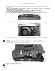
... M2.5 x 5-mm screw on the bottom of the palm rest. Page 48 Disconnect the contactless smartcard cable from the computer. Unroute the GPS antenna and USB connector from the system board. 7. NOTE: There are four snap hooks located in front of the mouse touchpad as part ... snap release. 13. Turn the computer topside and remove the sixteen M2.5 x 8-mm screws on the top of the computer. 11. Dell™ Latitude™ E6400 XFR Service Manual 6. These snap hooks may provide resistance during removal. Disconnect the finger print reader cable (optional), the speaker cable, and the touch...
... M2.5 x 5-mm screw on the bottom of the palm rest. Page 48 Disconnect the contactless smartcard cable from the computer. Unroute the GPS antenna and USB connector from the system board. 7. NOTE: There are four snap hooks located in front of the mouse touchpad as part ... snap release. 13. Turn the computer topside and remove the sixteen M2.5 x 8-mm screws on the top of the computer. 11. Dell™ Latitude™ E6400 XFR Service Manual 6. These snap hooks may provide resistance during removal. Disconnect the finger print reader cable (optional), the speaker cable, and the touch...
Service Manual
Page 49
... on the top of the palm rest. 5. Dell™ Latitude™ E6400 XFR Service Manual 21.2 Replacing the Palm Rest CAUTION: Before you begin any of the procedures in this is a new palm rest, remove the two cable access panels, the GPS access panel and the keyboard bracket before installation. ...1. Replace the one M.2.5 x 5-mm screw on Your Computer. 22 Modem 22.1 Removing the Modem Page 49 Reconnect the GPS antenna and USB connector (optional: see Replacing the Handle). 3. Replace the two cable access panels and secure each with your computer. Follow the...
... on the top of the palm rest. 5. Dell™ Latitude™ E6400 XFR Service Manual 21.2 Replacing the Palm Rest CAUTION: Before you begin any of the procedures in this is a new palm rest, remove the two cable access panels, the GPS access panel and the keyboard bracket before installation. ...1. Replace the one M.2.5 x 5-mm screw on Your Computer. 22 Modem 22.1 Removing the Modem Page 49 Reconnect the GPS antenna and USB connector (optional: see Replacing the Handle). 3. Replace the two cable access panels and secure each with your computer. Follow the...

E-Family Re-Image Guide
Page 23
...(Native Operating System) Airplane Mode Yes No No Broadcom Gigabit Yes Yes Yes LAN Dell Wireless WLAN 1397, Dell Wireless WLAN 1510 Yes Yes with Intel ProSet™ or Dell Yes with Wireless Wireless Client Utility (DCU) Zero Configuration (WZC) Intel Wireless LAN ...enable features offered on Dell E-Family thru Dell DCP Connection Manager, install the following application: • Dell ControlPoint Connection Manager Application The following table summarizes the Dell ControlPoint Connection Manager features offered on the notebook, such as Wi-Fi, Bluetooth GPS, UWB, and mobile...
...(Native Operating System) Airplane Mode Yes No No Broadcom Gigabit Yes Yes Yes LAN Dell Wireless WLAN 1397, Dell Wireless WLAN 1510 Yes Yes with Intel ProSet™ or Dell Yes with Wireless Wireless Client Utility (DCU) Zero Configuration (WZC) Intel Wireless LAN ...enable features offered on Dell E-Family thru Dell DCP Connection Manager, install the following application: • Dell ControlPoint Connection Manager Application The following table summarizes the Dell ControlPoint Connection Manager features offered on the notebook, such as Wi-Fi, Bluetooth GPS, UWB, and mobile...

E-Family Re-Image Guide
Page 24
... Wireless Client Utility (DCU) Disconnect on Ethernet WWAN Yes Yes with Intel ProSet or Dell No Wireless Client Utility (DCU) Dell Wireless 5530 Yes No No HSPA Mini-Card GPS Novatel™/ Ericsson® Yes Yes with Dell Mobile Broadband No Client Utility (DMBCU) for 5720 EVDO (from Novatel) No for 5530 HSPA (from...
... Wireless Client Utility (DCU) Disconnect on Ethernet WWAN Yes Yes with Intel ProSet or Dell No Wireless Client Utility (DCU) Dell Wireless 5530 Yes No No HSPA Mini-Card GPS Novatel™/ Ericsson® Yes Yes with Dell Mobile Broadband No Client Utility (DMBCU) for 5720 EVDO (from Novatel) No for 5530 HSPA (from...


