Service Manual
Page 20
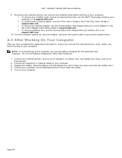
...cards, such as an ExpressCard Card, see the Dell™ Technology Guide on your computer or at support.dell.com. To undock from a docking station, see the E-Port User's Guide or the E-Port Plus User's Guide on support.dell.com. To remove the docking adapter, ... After Working On Your Computer After you have completed the replacement procedures, ensure you connect the external devices, cards, cables, etc. Dell™ Latitude™ E6400 XFR Service Manual 9. Turn the computer topside up, open the display, and press the power button to their electrical outlets. 5. Replace ...
...cards, such as an ExpressCard Card, see the Dell™ Technology Guide on your computer or at support.dell.com. To undock from a docking station, see the E-Port User's Guide or the E-Port Plus User's Guide on support.dell.com. To remove the docking adapter, ... After Working On Your Computer After you have completed the replacement procedures, ensure you connect the external devices, cards, cables, etc. Dell™ Latitude™ E6400 XFR Service Manual 9. Turn the computer topside up, open the display, and press the power button to their electrical outlets. 5. Replace ...

Service Manual
Page 55
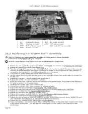
... 5 6 Lift the system board out of the base assembly to the bottom of board up while lifting the gasket at the multi-mode display port. 16. Dell™ Latitude™ E6400 XFR Service Manual 1 3 2 1 M2.5 x 5-mm screws (8) 2 M2 x 3-mm screws (2) 3 1394 connector NOTE: Smartcard assembly removed ...to disengage it from the multi-mode display port. 17. Lift the back-right corner of the base assembly. 20. Disconnect the DC cable,...
... 5 6 Lift the system board out of the base assembly to the bottom of board up while lifting the gasket at the multi-mode display port. 16. Dell™ Latitude™ E6400 XFR Service Manual 1 3 2 1 M2.5 x 5-mm screws (8) 2 M2 x 3-mm screws (2) 3 1394 connector NOTE: Smartcard assembly removed ...to disengage it from the multi-mode display port. 17. Lift the back-right corner of the base assembly. 20. Disconnect the DC cable,...
Service Manual
Page 56
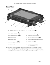
...number on the yellow label, located on the computer for AMT provisioning. Replace the two M2 x 3-mm screws for the multi-mode display port. 3. Install the Wi-Fi sniffer cable to the system board. 7. Replace the memory modules (see Replacing the Hard Drive). 15. ...Panel, the gasket for the multi-mode HD video connector is set properly, and the cable for the smartcard assembly is not interfering. 4. Dell™ Latitude™ E6400 XFR Service Manual 1 JSC1 Smartcard connector 5 JBIO1 BIO reader connector 2 JTP1 Touchpad connector 6 J1394 1394 cable connector 3 JSNIF1 Wi-Fi sniffer...
...number on the yellow label, located on the computer for AMT provisioning. Replace the two M2 x 3-mm screws for the multi-mode display port. 3. Install the Wi-Fi sniffer cable to the system board. 7. Replace the memory modules (see Replacing the Hard Drive). 15. ...Panel, the gasket for the multi-mode HD video connector is set properly, and the cable for the smartcard assembly is not interfering. 4. Dell™ Latitude™ E6400 XFR Service Manual 1 JSC1 Smartcard connector 5 JBIO1 BIO reader connector 2 JTP1 Touchpad connector 6 J1394 1394 cable connector 3 JSNIF1 Wi-Fi sniffer...

Service Manual
Page 72
Insert door hinge onto assembly and align the hinge divots. 2. Removing the VGA Panel Cover Follow the procedures in place over the VGA port. 2. Place the VGA Panel Cover in Before Working on Your Computer. Replace the two M3 x 3-mm screws. 3. Remove the two VGA Connector socket screws. 4. Replace ... in After Working on Your Computer. 37.15 1. 2. Place a scribe in the small opening and pull to remove. 37.16 Replacing the VGA Panel Cover 1. Dell™ Latitude™ E6400 XFR Service Manual 37.14 Replacing the VGA Door 1. Open the VGA door. 3.
Insert door hinge onto assembly and align the hinge divots. 2. Removing the VGA Panel Cover Follow the procedures in place over the VGA port. 2. Place the VGA Panel Cover in Before Working on Your Computer. Replace the two M3 x 3-mm screws. 3. Remove the two VGA Connector socket screws. 4. Replace ... in After Working on Your Computer. 37.15 1. 2. Place a scribe in the small opening and pull to remove. 37.16 Replacing the VGA Panel Cover 1. Dell™ Latitude™ E6400 XFR Service Manual 37.14 Replacing the VGA Door 1. Open the VGA door. 3.
Setup and Features Information Tech Sheet
Page 3
...fire. The computer turns on the fan when the computer gets hot. Fan noise is running. Do not store your Dell™ computer in the air vents. Page 3 Dell™ Latitude™ E6400 XFR Setup and Features Information Back View 1 2 3 4 5 6 7 8 9 1 PR-481™ Ultra-...Battery access panel 5 Battery/power lights 10 eSATA/USB connector ( ) 11 USB PowerShare connector ( ) 12 Sealed QuadCool™ thermal management 6 Multimode Display Port ( ) 13 Hard Disk Drive ( ) 7 AC adapter ( ) 14 Enclosed Smart-card reader (see Smart Cards) ( ) WARNING: Do not ...
...fire. The computer turns on the fan when the computer gets hot. Fan noise is running. Do not store your Dell™ computer in the air vents. Page 3 Dell™ Latitude™ E6400 XFR Setup and Features Information Back View 1 2 3 4 5 6 7 8 9 1 PR-481™ Ultra-...Battery access panel 5 Battery/power lights 10 eSATA/USB connector ( ) 11 USB PowerShare connector ( ) 12 Sealed QuadCool™ thermal management 6 Multimode Display Port ( ) 13 Hard Disk Drive ( ) 7 AC adapter ( ) 14 Enclosed Smart-card reader (see Smart Cards) ( ) WARNING: Do not ...

E-Family Re-Image Guide
Page 9
... and / or applications. Connection Manager - Security Manager • Privacy Screen • Touch Screen Digitizer (Only 6400 ATG) Dell Business Client E-Family Re-Image How-To Guide 9 Among these new hardware and technologies are not compatible with previous images built or... Rapid Recovery Technology) • eSATA • Intel AMT (Intel Active Management Technology) • Graphics controller (Intel and nVidia®) • Display Port • Network LoM (Intel and Broadcom®) • Wireless LAN • Wireless WAN • Bluetooth® / UWB • Broadcom Unified ...
... and / or applications. Connection Manager - Security Manager • Privacy Screen • Touch Screen Digitizer (Only 6400 ATG) Dell Business Client E-Family Re-Image How-To Guide 9 Among these new hardware and technologies are not compatible with previous images built or... Rapid Recovery Technology) • eSATA • Intel AMT (Intel Active Management Technology) • Graphics controller (Intel and nVidia®) • Display Port • Network LoM (Intel and Broadcom®) • Wireless LAN • Wireless WAN • Bluetooth® / UWB • Broadcom Unified ...


