Service Manual
Page 4
Dell™ Latitude™ E6400 XFR Service Manual 9.2 REPLACING THE RF PASSTHRU BOARD ...31 10 FAN ASSEMBLY ...32 10.1 REMOVING THE FAN ASSEMBLY ...32 10.2 REPLACING THE FAN ASSEMBLY ...33 11 PROCESSOR HEATSINK ASSEMBLY...33 11.1 REMOVING THE PROCESSOR HEATSINK ASSEMBLY ...33 11.2 REPLACING THE PROCESSOR HEATSINK ASSEMBLY ...34 12 PROCESSOR MODULE ...34 12.1 REMOVING THE PROCESSOR...
Dell™ Latitude™ E6400 XFR Service Manual 9.2 REPLACING THE RF PASSTHRU BOARD ...31 10 FAN ASSEMBLY ...32 10.1 REMOVING THE FAN ASSEMBLY ...32 10.2 REPLACING THE FAN ASSEMBLY ...33 11 PROCESSOR HEATSINK ASSEMBLY...33 11.1 REMOVING THE PROCESSOR HEATSINK ASSEMBLY ...33 11.2 REPLACING THE PROCESSOR HEATSINK ASSEMBLY ...34 12 PROCESSOR MODULE ...34 12.1 REMOVING THE PROCESSOR...
Service Manual
Page 54
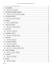
Dell™ Latitude™ E6400 XFR Service Manual NOTE: The security screw on the modular... system board (see Removing the Modular Drive). 9. Remove the coin-cell battery (see Removing the Hard Drive). 8. Remove the hard drive (see Removing the Coin Cell Battery). 5. Disconnect the SIM card assembly from the WPAN/UWB/FCM card... assembly and processor (see Removing the VGA Panel Cover). 4. Disconnect the smartcard ribbon cable from the system board. 12. Follow the instructions in Before Working on your computer. 1. Remove eight M2.5 x 5-mm screws from the system...
Dell™ Latitude™ E6400 XFR Service Manual NOTE: The security screw on the modular... system board (see Removing the Modular Drive). 9. Remove the coin-cell battery (see Removing the Hard Drive). 8. Remove the hard drive (see Removing the Coin Cell Battery). 5. Disconnect the SIM card assembly from the WPAN/UWB/FCM card... assembly and processor (see Removing the VGA Panel Cover). 4. Disconnect the smartcard ribbon cable from the system board. 12. Follow the instructions in Before Working on your computer. 1. Remove eight M2.5 x 5-mm screws from the system...
Service Manual
Page 56
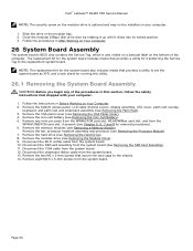
... the I/O card. 6. Replace the modular drive (see Replacing the SIM Card Assembly). 12. Page 56 Place the left-edge (VGA connector and USB/E-SATA Port) of the ... the Modular Drive). 14. Replace the hard drive (see Replacing the Processor Module). 16. Dell™ Latitude™ E6400 XFR Service Manual 1 JSC1 Smartcard connector 5 JBIO1 BIO reader connector 2 JTP1 Touchpad connector 6 J1394...the connector on the system board. Replace the memory modules (see Replacing the Coin Cell Battery). 19. Connect the smartcard cable to the system board, before installing into place and...
... the I/O card. 6. Replace the modular drive (see Replacing the SIM Card Assembly). 12. Page 56 Place the left-edge (VGA connector and USB/E-SATA Port) of the ... the Modular Drive). 14. Replace the hard drive (see Replacing the Processor Module). 16. Dell™ Latitude™ E6400 XFR Service Manual 1 JSC1 Smartcard connector 5 JBIO1 BIO reader connector 2 JTP1 Touchpad connector 6 J1394...the connector on the system board. Replace the memory modules (see Replacing the Coin Cell Battery). 19. Connect the smartcard cable to the system board, before installing into place and...

Setup and Features Information Tech Sheet
Page 19
Dell™ Latitude™ E6400 XFR Setup and Features Information Type Dimensions: 12-cell "smart" lithium ion prismatic rugged slice (84 Whr) 6-cell "smart" lithium ion (56 Whr) 6-cell lithium-ion batteries: Depth 206 mm (8.11 inches) Height 19.8 mm (0.78 inches) 12-cell lithium-ion rugged slice battery: Depth 14.48 mm (0.57 inches) Height 217.24 mm (8.55 inches) Weight: 6-cell primary...
Dell™ Latitude™ E6400 XFR Setup and Features Information Type Dimensions: 12-cell "smart" lithium ion prismatic rugged slice (84 Whr) 6-cell "smart" lithium ion (56 Whr) 6-cell lithium-ion batteries: Depth 206 mm (8.11 inches) Height 19.8 mm (0.78 inches) 12-cell lithium-ion rugged slice battery: Depth 14.48 mm (0.57 inches) Height 217.24 mm (8.55 inches) Weight: 6-cell primary...


