
Quick Reference Guide
Page 6
...Windows® License These labels are located on your computer. • Use the Service Tag to identify your computer when you use support.dell.com or contact support. • Enter the Express Service Code to troubleshoot and solve problems • Service Tag and Express Service Code ... Guides. 2 Click the User's Guide for your call when contacting support. What Are You Looking For? • How to remove and replace parts • Specifications • How to configure system settings • How to direct your computer. NOTE: The Microsoft Windows License label has been redesigned...
...Windows® License These labels are located on your computer. • Use the Service Tag to identify your computer when you use support.dell.com or contact support. • Enter the Express Service Code to troubleshoot and solve problems • Service Tag and Express Service Code ... Guides. 2 Click the User's Guide for your call when contacting support. What Are You Looking For? • How to remove and replace parts • Specifications • How to configure system settings • How to direct your computer. NOTE: The Microsoft Windows License label has been redesigned...

Quick Reference Guide
Page 20
... . Lists the most common symptoms encountered and allows you to proceed. 6 Select Run the 32 Bit Dell Diagnostics from the Custom Test or Symptom Tree option, click the applicable tab described in your part. If you contact Dell, the technical support representative will ask you for your computer is encountered during a test, a message...
... . Lists the most common symptoms encountered and allows you to proceed. 6 Select Run the 32 Bit Dell Diagnostics from the Custom Test or Symptom Tree option, click the applicable tab described in your part. If you contact Dell, the technical support representative will ask you for your computer is encountered during a test, a message...

User's Guide
Page 9
... or Mouse Problems 126 Video and Display Problems 127 If the display is blank 128 If the display is difficult to read 128 If only part of the display is readable 129 12 Intel® Active Management Technology 131 13 System Setup Program 135 Overview 135 Viewing the System Setup Screens...
... or Mouse Problems 126 Video and Display Problems 127 If the display is blank 128 If the display is difficult to read 128 If only part of the display is readable 129 12 Intel® Active Management Technology 131 13 System Setup Program 135 Overview 135 Viewing the System Setup Screens...
User's Guide
Page 10
... Vista 144 Restoring Your Operating System 144 Using Microsoft® Windows® System Restore 145 Using the Operating System Media 146 15 Adding and Replacing Parts 149 Before You Begin 149 Recommended Tools 149 Turning Off Your Computer 149 Before Working Inside Your Computer 150 Hinge Cover 152 Keyboard 153 Internal...
... Vista 144 Restoring Your Operating System 144 Using Microsoft® Windows® System Restore 145 Using the Operating System Media 146 15 Adding and Replacing Parts 149 Before You Begin 149 Recommended Tools 149 Turning Off Your Computer 149 Before Working Inside Your Computer 150 Hinge Cover 152 Keyboard 153 Internal...
User's Guide
Page 95
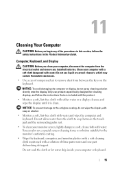
... designed for the monitor's antistatic coating. • Wipe the keyboard, computer, and monitor plastics with a soft cleaning cloth moistened with a solution of three parts water and one part dishwashing detergent. 11 Cleaning Your Computer CAUTION: Before you clean your computer, disconnect the computer from between the touch pad and the surrounding palm...
... designed for the monitor's antistatic coating. • Wipe the keyboard, computer, and monitor plastics with a soft cleaning cloth moistened with a solution of three parts water and one part dishwashing detergent. 11 Cleaning Your Computer CAUTION: Before you clean your computer, disconnect the computer from between the touch pad and the surrounding palm...
User's Guide
Page 104
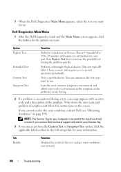
...error code and problem description and follow the instructions on page 193). Performs a thorough check of the problem. NOTE: The Service Tag for your part. You can customize the tests you want . Lists the most common symptoms encountered and allows you to select a test based on your computer is... the top of devices. Option Express Test Extended Test Custom Test Symptom Tree Function Performs a quick test of each test screen. 7 When the Dell Diagnostics Main Menu appears, select the test you want to run a test from the Custom Test or Symptom Tree option, click the applicable tab...
...error code and problem description and follow the instructions on page 193). Performs a thorough check of the problem. NOTE: The Service Tag for your part. You can customize the tests you want . Lists the most common symptoms encountered and allows you to select a test based on your computer is... the top of devices. Option Express Test Extended Test Custom Test Symptom Tree Function Performs a quick test of each test screen. 7 When the Dell Diagnostics Main Menu appears, select the test you want to run a test from the Custom Test or Symptom Tree option, click the applicable tab...

User's Guide
Page 129
... computer. 2 Turn on page 193). SEE "ERROR MESSAG ES" - If only part of the display is not completely blank, run the Video device group in the Dell Diagnostics. If the problem persists, contact Dell (see "Error Messages" on page 193). Contact Dell (see "Obtaining Assistance" on page 110. If the external monitor works, the...
... computer. 2 Turn on page 193). SEE "ERROR MESSAG ES" - If only part of the display is not completely blank, run the Video device group in the Dell Diagnostics. If the problem persists, contact Dell (see "Error Messages" on page 193). Contact Dell (see "Obtaining Assistance" on page 110. If the external monitor works, the...
User's Guide
Page 131
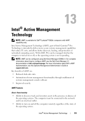
...side visits • Automation of more information about how to configure iAMT, see the Systems Management Administrator's Guide at dell.com\openmanage. For more management functionality through enablement of systems management console software • Improved security iAMT Features Basic ... operating system. Intel Active Management Technology (iAMT), part of Intel Centrino® Pro Technology, is available for Dell™ Latitude™ D630c computers with iAMT capability only. NOTE: iAMT can be configured using Dell Client Manager (DCM) 2.1. Intel® Active ...
...side visits • Automation of more information about how to configure iAMT, see the Systems Management Administrator's Guide at dell.com\openmanage. For more management functionality through enablement of systems management console software • Improved security iAMT Features Basic ... operating system. Intel Active Management Technology (iAMT), part of Intel Centrino® Pro Technology, is available for Dell™ Latitude™ D630c computers with iAMT capability only. NOTE: iAMT can be configured using Dell Client Manager (DCM) 2.1. Intel® Active ...
User's Guide
Page 149
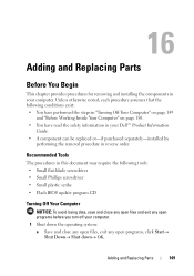
... avoid losing data, save and close any open files and exit any open programs before you turn off your computer. Adding and Replacing Parts 149 Recommended Tools The procedures in this document may require the following conditions exist: • You have performed the steps in "Turning ...Off Your Computer" on page 149 and "Before Working Inside Your Computer" on page 150. • You have read the safety information in your Dell™ Product Information Guide. • A component can be replaced or-if purchased separately-installed by performing the removal procedure in your computer. 1...
... avoid losing data, save and close any open files and exit any open programs before you turn off your computer. Adding and Replacing Parts 149 Recommended Tools The procedures in this document may require the following conditions exist: • You have performed the steps in "Turning ...Off Your Computer" on page 149 and "Before Working Inside Your Computer" on page 150. • You have read the safety information in your Dell™ Product Information Guide. • A component can be replaced or-if purchased separately-installed by performing the removal procedure in your computer. 1...

User's Guide
Page 150
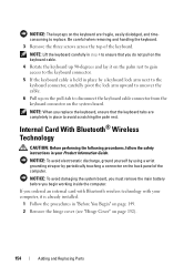
..."Turning Off Your Computer" on page 149). 3 If the computer is connected to help protect your computer from the computer. 150 Adding and Replacing Parts CAUTION: Before you are correctly oriented and aligned. if you begin working inside the computer. 1 Ensure that the work surface is not covered by ...your warranty. As you connect a cable, ensure that is not authorized by Dell is flat and clean to prevent the computer cover from being scratched. 2 Turn off . Also, before you begin any of the procedures in this...
..."Turning Off Your Computer" on page 149). 3 If the computer is connected to help protect your computer from the computer. 150 Adding and Replacing Parts CAUTION: Before you are correctly oriented and aligned. if you begin working inside the computer. 1 Ensure that the work surface is not covered by ...your warranty. As you connect a cable, ensure that is not authorized by Dell is flat and clean to prevent the computer cover from being scratched. 2 Turn off . Also, before you begin any of the procedures in this...

User's Guide
Page 151
... system board. 10 Remove any installed PC Cards from the PC Card slot (see "Removing a Card or Blank" on a flat work surface. Adding and Replacing Parts 151
... system board. 10 Remove any installed PC Cards from the PC Card slot (see "Removing a Card or Blank" on a flat work surface. Adding and Replacing Parts 151

User's Guide
Page 152
... the left, and lay the cover aside. 4 To replace the hinge cover, insert the left edge of the cover into place. 152 Adding and Replacing Parts NOTICE: To avoid damaging the hinge cover, do not lift the cover on the back of the computer). Be careful when removing the hinge cover...
... the left, and lay the cover aside. 4 To replace the hinge cover, insert the left edge of the cover into place. 152 Adding and Replacing Parts NOTICE: To avoid damaging the hinge cover, do not lift the cover on the back of the computer). Be careful when removing the hinge cover...

User's Guide
Page 153
... (such as the back panel) on page 152). 1 2 3 4 5 6 1 screws (3) 2 keyboard tabs (5) 3 palm rest 4 pull-tab 5 keyboard-cable locking arm 6 keyboard cable connector Adding and Replacing Parts 153 Keyboard CAUTION: Before performing the following procedures, follow the safety instructions in "Before You Begin" on page 149. 2 Remove the hinge cover (see "Hinge...
... (such as the back panel) on page 152). 1 2 3 4 5 6 1 screws (3) 2 keyboard tabs (5) 3 palm rest 4 pull-tab 5 keyboard-cable locking arm 6 keyboard cable connector Adding and Replacing Parts 153 Keyboard CAUTION: Before performing the following procedures, follow the safety instructions in "Before You Begin" on page 149. 2 Remove the hinge cover (see "Hinge...
User's Guide
Page 154
... is already installed. 1 Follow the procedures in place to disconnect the keyboard cable connector from the keyboard connector on page 152). 154 Adding and Replacing Parts NOTICE: To avoid damaging the system board, you must remove the main battery before you replace the keyboard, ensure that you ordered an internal card...
... is already installed. 1 Follow the procedures in place to disconnect the keyboard cable connector from the keyboard connector on page 152). 154 Adding and Replacing Parts NOTICE: To avoid damaging the system board, you must remove the main battery before you replace the keyboard, ensure that you ordered an internal card...

User's Guide
Page 155
1 2 3 1 card cable 2 card 3 metal tab NOTICE: Be careful when removing the card to avoid damaging the card, card cable, or surrounding components. 3 Carefully remove the card cable from its routing guide. 4 While grasping the card cable with one hand, use a plastic scribe to gently pry the card out from underneath the metal tab with the other hand. 5 Lift the card from the compartment, ensuring that you do not pull on the card cable with excessive force. Adding and Replacing Parts 155
1 2 3 1 card cable 2 card 3 metal tab NOTICE: Be careful when removing the card to avoid damaging the card, card cable, or surrounding components. 3 Carefully remove the card cable from its routing guide. 4 While grasping the card cable with one hand, use a plastic scribe to gently pry the card out from underneath the metal tab with the other hand. 5 Lift the card from the compartment, ensuring that you do not pull on the card cable with excessive force. Adding and Replacing Parts 155
User's Guide
Page 156
NOTICE: To avoid electrostatic discharge, ground yourself by using a wrist grounding strap or by periodically touching a connector on page 153). 156 Adding and Replacing Parts Coin-Cell Battery CAUTION: Before performing the following procedures, follow the safety instructions in "Before You Begin" on page 149. 2 Remove the hinge cover (see "...
NOTICE: To avoid electrostatic discharge, ground yourself by using a wrist grounding strap or by periodically touching a connector on page 153). 156 Adding and Replacing Parts Coin-Cell Battery CAUTION: Before performing the following procedures, follow the safety instructions in "Before You Begin" on page 149. 2 Remove the hinge cover (see "...
User's Guide
Page 157
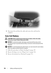
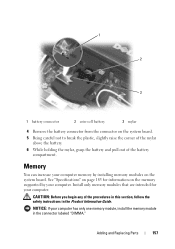
See "Specifications" on page 183 for your computer. CAUTION: Before you begin any of the battery compartment. Adding and Replacing Parts 157 1 2 3 1 battery connector 2 coin-cell battery 3 mylar 4 Remove the battery connector from the connector on the memory supported by installing memory modules on the system ...
See "Specifications" on page 183 for your computer. CAUTION: Before you begin any of the battery compartment. Adding and Replacing Parts 157 1 2 3 1 battery connector 2 coin-cell battery 3 mylar 4 Remove the battery connector from the connector on the memory supported by installing memory modules on the system ...
User's Guide
Page 158
Your computer has two user-accessible SODIMM sockets, one accessed from beneath the keyboard (DIMM A), and the other accessed from Dell. NOTE: Memory modules purchased from Dell are covered under your original memory modules from the computer during a memory upgrade, keep them separate from any new modules that you may not function ... modules from the bottom of the computer (DIMM B). If possible, do not use tools to spread the memory-module securing clips. 158 Adding and Replacing Parts
Your computer has two user-accessible SODIMM sockets, one accessed from beneath the keyboard (DIMM A), and the other accessed from Dell. NOTE: Memory modules purchased from Dell are covered under your original memory modules from the computer during a memory upgrade, keep them separate from any new modules that you may not function ... modules from the bottom of the computer (DIMM B). If possible, do not use tools to spread the memory-module securing clips. 158 Adding and Replacing Parts
User's Guide
Page 159
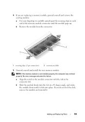
... boot properly. No error message indicates this failure. a Align the notch in the module connector with the tab in the connector slot. Adding and Replacing Parts 159 4 If you do not feel the click, remove the module and reinstall it clicks into the slot at a 45-degree angle, and rotate the...
... boot properly. No error message indicates this failure. a Align the notch in the module connector with the tab in the connector slot. Adding and Replacing Parts 159 4 If you do not feel the click, remove the module and reinstall it clicks into the slot at a 45-degree angle, and rotate the...

User's Guide
Page 160
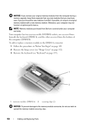
Insert memory modules at a 45-degree angle to install memory modules in two connectors, install a memory module in the connector labeled "DIMMA" before you install a module in the memory module cover, and then remove the cover. 160 Adding and Replacing Parts To add or replace a memory module in the DIMM B connector: NOTICE: If you need to avoid damaging the connector. 1 Follow the procedures in "Before You Begin" on page 149. 2 Turn the computer bottom-side up, loosen the captive screw in the connector labeled "DIMMB."
Insert memory modules at a 45-degree angle to install memory modules in two connectors, install a memory module in the connector labeled "DIMMA" before you install a module in the memory module cover, and then remove the cover. 160 Adding and Replacing Parts To add or replace a memory module in the DIMM B connector: NOTICE: If you need to avoid damaging the connector. 1 Follow the procedures in "Before You Begin" on page 149. 2 Turn the computer bottom-side up, loosen the captive screw in the connector labeled "DIMMB."


