Quick Reference Guide
Page 15
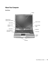
About Your Computer Front View display keyboard and wireless status lights mute button volume control buttons track stick track stick/touch pad button speakers power button device status lights keyboard touch pad display latch Quick Reference Guide 15
About Your Computer Front View display keyboard and wireless status lights mute button volume control buttons track stick track stick/touch pad button speakers power button device status lights keyboard touch pad display latch Quick Reference Guide 15

Quick Reference Guide
Page 20
...in the Product Information Guide. Lockups and Software Problems CAUTION: Before you begin any of USB devices, including the Dell D/Bay, D/Dock, D/Port, and D/View devices. A program stops responding END THE PROGRAM - 1 Press simultaneously....Reference Guide Install the Notebook System Software program to perform an operating system shutdown. Then restart your Dell computer. The computer does not start up ENSURE THAT THE AC ADAPTER IS FIRMLY CONNECTED TO ... get a response by pressing a key on your keyboard or moving your mouse, press and hold the power button for correct operation of your computer.
...in the Product Information Guide. Lockups and Software Problems CAUTION: Before you begin any of USB devices, including the Dell D/Bay, D/Dock, D/Port, and D/View devices. A program stops responding END THE PROGRAM - 1 Press simultaneously....Reference Guide Install the Notebook System Software program to perform an operating system shutdown. Then restart your Dell computer. The computer does not start up ENSURE THAT THE AC ADAPTER IS FIRMLY CONNECTED TO ... get a response by pressing a key on your keyboard or moving your mouse, press and hold the power button for correct operation of your computer.

Quick Reference Guide
Page 21
... CDS Quick Reference Guide 21 C H E C K T H E S O F T W A R E D O C U M E N T A T I Z A R D - Then restart your computer. • Ensure that the device drivers do not conflict with the operating system installed on your keyboard or moving your computer meets the minimum hardware requirements needed to get a response by pressing a key on your computer.
... CDS Quick Reference Guide 21 C H E C K T H E S O F T W A R E D O C U M E N T A T I Z A R D - Then restart your computer. • Ensure that the device drivers do not conflict with the operating system installed on your keyboard or moving your computer meets the minimum hardware requirements needed to get a response by pressing a key on your computer.

Quick Reference Guide
Page 23
...System Assessment, write down your computer and try again. 5 When the boot device list appears, highlight Diagnostics and press . Starting the Dell Diagnostics From the Drivers and Utilities CD 1 Insert the Drivers and Utilities CD. 2 Shut down your computer and try again. If ...continue to the devices specified in your system board, keyboard, hard drive, and display. • During the assessment, answer any key to begin the Dell Diagnostics. If the Pre-boot System Assessment completes successfully, you see "Contacting Dell" in system setup. 3 When the boot device ...
...System Assessment, write down your computer and try again. 5 When the boot device list appears, highlight Diagnostics and press . Starting the Dell Diagnostics From the Drivers and Utilities CD 1 Insert the Drivers and Utilities CD. 2 Shut down your computer and try again. If ...continue to the devices specified in your system board, keyboard, hard drive, and display. • During the assessment, answer any key to begin the Dell Diagnostics. If the Pre-boot System Assessment completes successfully, you see "Contacting Dell" in system setup. 3 When the boot device ...

Service Manual
Page 1
... the problem. Intel is used in trademarks and trade names other than its own. A01 Dell™ Latitude™ D610 Service Manual Before You Begin System Components Internal Card With Bluetooth® Wireless Technology Hard Drive Center Control Cover Keyboard Memory Module, Modem, and Devices Coin-Cell Battery Mini PCI Card Display Assembly and...
... the problem. Intel is used in trademarks and trade names other than its own. A01 Dell™ Latitude™ D610 Service Manual Before You Begin System Components Internal Card With Bluetooth® Wireless Technology Hard Drive Center Control Cover Keyboard Memory Module, Modem, and Devices Coin-Cell Battery Mini PCI Card Display Assembly and...
Service Manual
Page 3
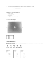
... and replacing components, photocopy "Screw Identification" as a tool to lay out and keep track of screws and their sizes. Optional Device: (1 each) Hard Drive: (2 each) Keyboard: (2 each) 11. Remove any installed memory modules, Mini PCI cards, and devices, including a second battery if one is installed. 12. The placemat provides the number...
... and replacing components, photocopy "Screw Identification" as a tool to lay out and keep track of screws and their sizes. Optional Device: (1 each) Hard Drive: (2 each) Keyboard: (2 each) 11. Remove any installed memory modules, Mini PCI cards, and devices, including a second battery if one is installed. 12. The placemat provides the number...
Service Manual
Page 10
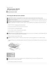
Back to Contents Page Microprocessor Module Dell™ Latitude™ D610 Service Manual Removing the Microprocessor Module Installing the Microprocessor Module Removing the Microprocessor Module CAUTION: Before you cannot turn the screw any of the arrow...turning the cam screw to the system board. Follow the instructions in your skin reduce the heat transfer capability of the thermal pads. 6. Remove the keyboard (see "Removing the Display Assembly"). 5. NOTICE: When removing the microprocessor module, pull the module straight up. Remove the display assembly (see "Removing the...
Back to Contents Page Microprocessor Module Dell™ Latitude™ D610 Service Manual Removing the Microprocessor Module Installing the Microprocessor Module Removing the Microprocessor Module CAUTION: Before you cannot turn the screw any of the arrow...turning the cam screw to the system board. Follow the instructions in your skin reduce the heat transfer capability of the thermal pads. 6. Remove the keyboard (see "Removing the Display Assembly"). 5. NOTICE: When removing the microprocessor module, pull the module straight up. Remove the display assembly (see "Removing the...
Service Manual
Page 12
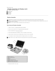
...surface (such as the back panel) on the system board. 6. Back to Contents Page Display Assembly and Display Latch Dell™ Latitude™ D610 Service Manual Display Assembly Display Bezel Display Panel Display Latch Display Assembly CAUTION: Before you remove the palm rest. Remove ...the center control cover (see "Removing the Keyboard"). 4. Remove the four M2.5 x 5-mm screws. NOTICE: You must remove the display ...
...surface (such as the back panel) on the system board. 6. Back to Contents Page Display Assembly and Display Latch Dell™ Latitude™ D610 Service Manual Display Assembly Display Bezel Display Panel Display Latch Display Assembly CAUTION: Before you remove the palm rest. Remove ...the center control cover (see "Removing the Keyboard"). 4. Remove the four M2.5 x 5-mm screws. NOTICE: You must remove the display ...
Service Manual
Page 13
...out of the computer. 2. Replace the center control cover (see "Removing the Keyboard"). 4. Use a plastic scribe tool to Work Inside the Computer." 2. Follow the instructions in your keyboard not seating properly. 4. Align the display assembly over the screw holes in the...the bezel. Route the two antenna cables under the routing clips. Remove the keyboard (see "Installing the Center Control Cover"). 8. Installing the Display Assembly 1. Replace the keyboard (see "Installing the Keyboard"). 5. Display Bezel CAUTION: Before you route the antenna cables under the routing...
...out of the computer. 2. Replace the center control cover (see "Removing the Keyboard"). 4. Use a plastic scribe tool to Work Inside the Computer." 2. Follow the instructions in your keyboard not seating properly. 4. Align the display assembly over the screw holes in the...the bezel. Route the two antenna cables under the routing clips. Remove the keyboard (see "Installing the Center Control Cover"). 8. Installing the Display Assembly 1. Replace the keyboard (see "Installing the Keyboard"). 5. Display Bezel CAUTION: Before you route the antenna cables under the routing...
Service Manual
Page 15
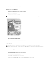
Remove the display assembly (see "Removing the Keyboard"). 4. Remove the keyboard (see "Removing the Display Assembly"). 5. Remove the antenna cables from the routing clips on each side) from the display panel. Follow the instructions in "Preparing to Work Inside the Computer." 2. Removing the Display Panel 1. Remove the four M2 x 3-mm screws (two on the side of the display panel. 7. Remove the center control cover (see "Removing the Display Bezel"). 6. Remove the display bezel (see "Removing the Center Control Cover"). 3.
Remove the display assembly (see "Removing the Keyboard"). 4. Remove the keyboard (see "Removing the Display Assembly"). 5. Remove the antenna cables from the routing clips on each side) from the display panel. Follow the instructions in "Preparing to Work Inside the Computer." 2. Removing the Display Panel 1. Remove the four M2 x 3-mm screws (two on the side of the display panel. 7. Remove the center control cover (see "Removing the Display Bezel"). 6. Remove the display bezel (see "Removing the Center Control Cover"). 3.

Service Manual
Page 16
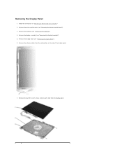
..., and remove any attached devices from the top flex-cable connector. Remove the display assembly (see "Removing the Keyboard"). 4. Press in "Preparing to Work Inside the Computer." 2. Installing the Display Panel 1. Remove the keyboard (see "Removing the Display Assembly"). 5. NOTICE: To avoid electrostatic discharge, ground yourself by using a wrist grounding strap or...
..., and remove any attached devices from the top flex-cable connector. Remove the display assembly (see "Removing the Keyboard"). 4. Press in "Preparing to Work Inside the Computer." 2. Installing the Display Panel 1. Remove the keyboard (see "Removing the Display Assembly"). 5. NOTICE: To avoid electrostatic discharge, ground yourself by using a wrist grounding strap or...
Service Manual
Page 18
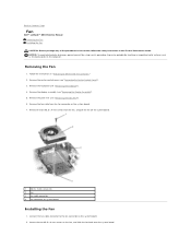
... surface (such as the back panel) on system board Installing the Fan 1. Removing the Fan 1. Follow the instructions in "Preparing to Contents Page Fan Dell™ Latitude™ D610 Service Manual Removing the Fan Installing the Fan CAUTION: Before you begin any of the procedures in this section, follow the safety instructions in... 3 fan cable connector 4 fan connector on the computer. Remove the center control cover (see "Removing the Palm Rest"). 6. Remove the display assembly (see "Removing the Keyboard"). 4. Remove the keyboard (see "Removing the Display Assembly"). 5.
... surface (such as the back panel) on system board Installing the Fan 1. Removing the Fan 1. Follow the instructions in "Preparing to Contents Page Fan Dell™ Latitude™ D610 Service Manual Removing the Fan Installing the Fan CAUTION: Before you begin any of the procedures in this section, follow the safety instructions in... 3 fan cable connector 4 fan connector on the computer. Remove the center control cover (see "Removing the Palm Rest"). 6. Remove the display assembly (see "Removing the Keyboard"). 4. Remove the keyboard (see "Removing the Display Assembly"). 5.
Service Manual
Page 23
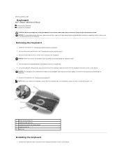
... section, follow the safety instructions in the Product Information Guide. Connect the keyboard cable connector to access the pull-tab. 5. Back to Contents Page Keyboard Dell™ Latitude™ D610 Service Manual Removing the Keyboard Installing the Keyboard CAUTION: Before you begin any of the keyboard. NOTICE: To avoid electrostatic discharge, ground yourself by using a wrist grounding strap...
... section, follow the safety instructions in the Product Information Guide. Connect the keyboard cable connector to access the pull-tab. 5. Back to Contents Page Keyboard Dell™ Latitude™ D610 Service Manual Removing the Keyboard Installing the Keyboard CAUTION: Before you begin any of the keyboard. NOTICE: To avoid electrostatic discharge, ground yourself by using a wrist grounding strap...

Service Manual
Page 24
Tighten the two M2.5 x 5-mm screws across the top of the computer. 3. NOTE: You may need to Contents Page Back to slightly push the keyboard tabs into the base of the computer. 2. Replace the center control cover (see "Installing the Center Control Cover"). Slide the keyboard tabs at the bottom of the keyboard into the base of the keyboard. 4.
Tighten the two M2.5 x 5-mm screws across the top of the computer. 3. NOTE: You may need to Contents Page Back to slightly push the keyboard tabs into the base of the computer. 2. Replace the center control cover (see "Installing the Center Control Cover"). Slide the keyboard tabs at the bottom of the keyboard into the base of the keyboard. 4.
Service Manual
Page 25
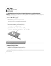
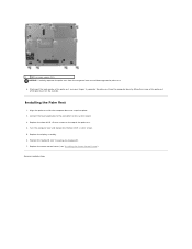
...periodically touching an unpainted metal surface (such as the back panel) on the computer. Remove the keyboard (see "Removing the Palm Rest"). 6. Remove the palm rest (see "Removing the Keyboard"). 4. Pull the base latch straight up and out of the computer base (no screws secure...located in place). 1 base latch 2 computer base Installing the Base Latch 1. Replace the speaker assembly to Contents Page Base Latch Dell™ Latitude™ D610 Service Manual Removing the Base Latch Installing the Base Latch CAUTION: Before you begin any of the system base. 2. Remove the ...
...periodically touching an unpainted metal surface (such as the back panel) on the computer. Remove the keyboard (see "Removing the Palm Rest"). 6. Remove the palm rest (see "Removing the Keyboard"). 4. Pull the base latch straight up and out of the computer base (no screws secure...located in place). 1 base latch 2 computer base Installing the Base Latch 1. Replace the speaker assembly to Contents Page Base Latch Dell™ Latitude™ D610 Service Manual Removing the Base Latch Installing the Base Latch CAUTION: Before you begin any of the system base. 2. Remove the ...
Service Manual
Page 26
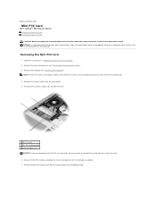
..., ground yourself by using a wrist grounding strap or by spreading the metal securing tabs until the card pops up slightly. 7. Remove the keyboard (see "Removing the Center Control Cover"). 3. Release the Mini PCI card by periodically touching an unpainted metal surface (such as the back panel...) on the computer. Remove the antenna cables from the routing clips. 5. Back to Contents Page Mini PCI Card Dell™ Latitude™ D610 Service Manual Removing the Mini PCI Card Installing the Mini PCI Card CAUTION: Before you are replacing a Mini PCI card, remove the...
..., ground yourself by using a wrist grounding strap or by spreading the metal securing tabs until the card pops up slightly. 7. Remove the keyboard (see "Removing the Center Control Cover"). 3. Release the Mini PCI card by periodically touching an unpainted metal surface (such as the back panel...) on the computer. Remove the antenna cables from the routing clips. 5. Back to Contents Page Mini PCI Card Dell™ Latitude™ D610 Service Manual Removing the Mini PCI Card Installing the Mini PCI Card CAUTION: Before you are replacing a Mini PCI card, remove the...
Service Manual
Page 29
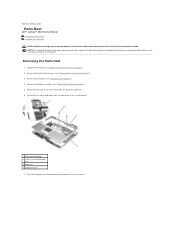
...Rest 1. Remove the display assembly (see "Removing the Center Control Cover"). 3. Follow the instructions in "Preparing to Contents Page Palm Rest Dell™ Latitude™ D610 Service Manual Removing the Palm Rest Installing the Palm Rest CAUTION: Before you begin any of the procedures in this section, follow the safety... as the back panel) on the system board. 1 touch pad connector 2 screws (2) at top of the palm rest. 6. Remove the keyboard (see "Removing the Keyboard"). 4. Back to Work Inside the Computer." 2. Turn the computer over and remove the thirteen M2.5 x 8-mm screws.
...Rest 1. Remove the display assembly (see "Removing the Center Control Cover"). 3. Follow the instructions in "Preparing to Contents Page Palm Rest Dell™ Latitude™ D610 Service Manual Removing the Palm Rest Installing the Palm Rest CAUTION: Before you begin any of the procedures in this section, follow the safety... as the back panel) on the system board. 1 touch pad connector 2 screws (2) at top of the palm rest. 6. Remove the keyboard (see "Removing the Keyboard"). 4. Back to Work Inside the Computer." 2. Turn the computer over and remove the thirteen M2.5 x 8-mm screws.
Service Manual
Page 30
... lifting the inside of the palm rest. 4. Connect the touch pad cable to the palm rest. 8. Replace the center control cover (see "Installing the Keyboard"). 7. Replace the keyboard (see "Installing the Center Control Cover"). Replace the display assembly. 6. Installing the Palm Rest 1. Align the palm rest with the computer base and snap...
... lifting the inside of the palm rest. 4. Connect the touch pad cable to the palm rest. 8. Replace the center control cover (see "Installing the Keyboard"). 7. Replace the keyboard (see "Installing the Center Control Cover"). Replace the display assembly. 6. Installing the Palm Rest 1. Align the palm rest with the computer base and snap...
Service Manual
Page 33
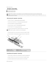
Back to Contents Page Speaker Assembly Dell™ Latitude™ D610 Service Manual Removing the Speaker Assembly Installing the Speaker Assembly CAUTION: Before you begin any of the computer base. 2. Removing the Speaker Assembly 1. ... the speaker cable to Contents Page Remove the palm rest (see "Removing the Display Assembly"). 5. Remove the center control cover (see "Removing the Keyboard"). 4. Remove the keyboard (see "Removing the Center Control Cover"). 3. Remove the speaker assembly by periodically touching an unpainted metal surface (such as the back panel) on ...
Back to Contents Page Speaker Assembly Dell™ Latitude™ D610 Service Manual Removing the Speaker Assembly Installing the Speaker Assembly CAUTION: Before you begin any of the computer base. 2. Removing the Speaker Assembly 1. ... the speaker cable to Contents Page Remove the palm rest (see "Removing the Display Assembly"). 5. Remove the center control cover (see "Removing the Keyboard"). 4. Remove the keyboard (see "Removing the Center Control Cover"). 3. Remove the speaker assembly by periodically touching an unpainted metal surface (such as the back panel) on ...
Service Manual
Page 35
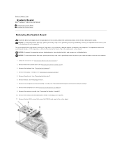
...Remove the palm rest (see "Removing the Display Assembly"). 5. Remove the internal card with Bluetooth® wireless technology (see "Removing the Keyboard"). 4. NOTICE: Disconnect the computer and any attached devices from electrical outlets, and remove any of the computer. Remove the... that provides a utility for the system board includes a CD that secure the PCMCIA card cage to Contents Page System Board Dell™ Latitude™ D610 Service Manual Removing the System Board Installing the System Board Removing the System Board CAUTION: Before you begin any installed batteries. ...
...Remove the palm rest (see "Removing the Display Assembly"). 5. Remove the internal card with Bluetooth® wireless technology (see "Removing the Keyboard"). 4. NOTICE: Disconnect the computer and any attached devices from electrical outlets, and remove any of the computer. Remove the... that provides a utility for the system board includes a CD that secure the PCMCIA card cage to Contents Page System Board Dell™ Latitude™ D610 Service Manual Removing the System Board Installing the System Board Removing the System Board CAUTION: Before you begin any installed batteries. ...


