
Quick Reference Guide
Page 9
...during the initial 1-year period of the procedures in this section, follow the safety instructions located in the battery bay. For more information about the Dell warranty for your computer. NOTE: Battery operating time (the time the battery can hold a charge) decreases over time. One battery is used, you... button NOTE: Do not connect the computer to the docking device until the computer has been turned on how often the battery is used and the conditions under which it is not connected to turn on the computer. 4 Open the computer display and press the power button to an electrical ...
...during the initial 1-year period of the procedures in this section, follow the safety instructions located in the battery bay. For more information about the Dell warranty for your computer. NOTE: Battery operating time (the time the battery can hold a charge) decreases over time. One battery is used, you... button NOTE: Do not connect the computer to the docking device until the computer has been turned on how often the battery is used and the conditions under which it is not connected to turn on the computer. 4 Open the computer display and press the power button to an electrical ...

Quick Reference Guide
Page 13
... outlet and allow the computer and the battery to cool to an electrical outlet. For more information about resolving problems with the computer turned off. During that minimal battery operating time remains. If two batteries are installed, the low-battery warning means that the combined charge of...start charging if the light flashes alternately green and orange. If the battery runs completely out of both batteries is longer with the computer turned on. A low-battery warning occurs when the battery charge is at a critically low level. Quick Reference Guide 13 Then connect the computer...
... outlet and allow the computer and the battery to cool to an electrical outlet. For more information about resolving problems with the computer turned off. During that minimal battery operating time remains. If two batteries are installed, the low-battery warning means that the combined charge of...start charging if the light flashes alternately green and orange. If the battery runs completely out of both batteries is longer with the computer turned on. A low-battery warning occurs when the battery charge is at a critically low level. Quick Reference Guide 13 Then connect the computer...

Quick Reference Guide
Page 14
...unsaved data. 1 Ensure that came with the computer in a power management mode, or connected to an electrical outlet. 2 If the computer is turned off, suspended in standby mode, you choose to replace the battery with your computer for instructions. 3 Slide and hold the battery-bay (or ...module-bay) latch release on the bottom of time. www.dell.com | support.dell.com Removing a Battery CAUTION: Before performing these procedures, disconnect the modem from the bay. NOTICE: If you have up to 1 minute ...
...unsaved data. 1 Ensure that came with the computer in a power management mode, or connected to an electrical outlet. 2 If the computer is turned off, suspended in standby mode, you choose to replace the battery with your computer for instructions. 3 Slide and hold the battery-bay (or ...module-bay) latch release on the bottom of time. www.dell.com | support.dell.com Removing a Battery CAUTION: Before performing these procedures, disconnect the modem from the bay. NOTICE: If you have up to 1 minute ...

Quick Reference Guide
Page 20
...CAUTION: Before you are unable to 10 seconds until the computer turns off. TU R N T H E C O M P U T E R O F F - A program stops responding END THE PROGRAM - 1 Press simultaneously. 2 Click Applications. 3 Click the program that provides critical updates for Dell 3.5-inch USB floppy drives, Intel® Pentium® M ... the correct operation of the procedures in this section, follow the safety instructions in the Product Information Guide. www.dell.com | support.dell.com Solving Problems Notebook System Software Notebook System Software (NSS) is a utility that is no longer responding. ...
...CAUTION: Before you are unable to 10 seconds until the computer turns off. TU R N T H E C O M P U T E R O F F - A program stops responding END THE PROGRAM - 1 Press simultaneously. 2 Click Applications. 3 Click the program that provides critical updates for Dell 3.5-inch USB floppy drives, Intel® Pentium® M ... the correct operation of the procedures in this section, follow the safety instructions in the Product Information Guide. www.dell.com | support.dell.com Solving Problems Notebook System Software Notebook System Software (NSS) is a utility that is no longer responding. ...

Quick Reference Guide
Page 21
... run the software. See the software documentation for information. • Ensure that the program is designed for at least 8 to 10 seconds until the computer turns off. BACK UP YOUR FILES IMMEDIATELY USE A VIRUS-SCANNING PROGRAM TO CHECK THE HARD DRIVE, FLOPPY DISKS, OR CDS Quick Reference Guide 21 The Program...
... run the software. See the software documentation for information. • Ensure that the program is designed for at least 8 to 10 seconds until the computer turns off. BACK UP YOUR FILES IMMEDIATELY USE A VIRUS-SCANNING PROGRAM TO CHECK THE HARD DRIVE, FLOPPY DISKS, OR CDS Quick Reference Guide 21 The Program...

Quick Reference Guide
Page 23
...the computer. Starting the Dell Diagnostics From the Drivers and Utilities CD 1 Insert ... error code(s) and see "Contacting Dell" in system setup. 3 When the... the computer, press ; to the Dell Diagnostics. When the DELL logo appears, press immediately. NOTE:...operating system logo appears, continue to begin the Dell Diagnostics. The computer runs the Pre-boot ...to wait until you receive the message Booting Dell Diagnostic Utility Partition. NOTE: If you ... found, run the Starting the Dell Diagnostics From the Drivers and Utilities...Dell Diagnostics from the menu that appear. • If...
...the computer. Starting the Dell Diagnostics From the Drivers and Utilities CD 1 Insert ... error code(s) and see "Contacting Dell" in system setup. 3 When the... the computer, press ; to the Dell Diagnostics. When the DELL logo appears, press immediately. NOTE:...operating system logo appears, continue to begin the Dell Diagnostics. The computer runs the Pre-boot ...to wait until you receive the message Booting Dell Diagnostic Utility Partition. NOTE: If you ... found, run the Starting the Dell Diagnostics From the Drivers and Utilities...Dell Diagnostics from the menu that appear. • If...
Service Manual
Page 2
... 7. Save any installed PC Cards from the PC Card slot. 9. Disconnect the computer from the computer. 8. Close the display and turn the computer upside down the computer using the computer operating system, press and hold the battery-bay latch release on your computer. NOTICE:... board, you must remove the main battery before you service the computer. 10. Back to Contents Page Before You Begin Dell™ Latitude™ D610 Service Manual Preparing to Work Inside the Computer Recommended Tools Computer Orientation Screw Identification Preparing to Work Inside the Computer CAUTION: ...
... 7. Save any installed PC Cards from the PC Card slot. 9. Disconnect the computer from the computer. 8. Close the display and turn the computer upside down the computer using the computer operating system, press and hold the battery-bay latch release on your computer. NOTICE:... board, you must remove the main battery before you service the computer. 10. Back to Contents Page Before You Begin Dell™ Latitude™ D610 Service Manual Preparing to Work Inside the Computer Recommended Tools Computer Orientation Screw Identification Preparing to Work Inside the Computer CAUTION: ...
Service Manual
Page 5
... reboot. 3. When the flash update is installed properly. Press , select Save changes and reboot, and press to Contents Page Flashing the BIOS Dell™ Latitude™ D610 Service Manual 1. Remove the flash BIOS update program floppy or CD from a CD before inserting the CD. 2. NOTE: If you use a... the BIOS, set up the computer to boot from the drive and restart the computer. Insert the BIOS update program floppy or CD, and turn on the screen. Back to save configuration changes. 6. Press during POST to reset the computer defaults. 5. Press and to enter the system ...
... reboot. 3. When the flash update is installed properly. Press , select Save changes and reboot, and press to Contents Page Flashing the BIOS Dell™ Latitude™ D610 Service Manual 1. Remove the flash BIOS update program floppy or CD from a CD before inserting the CD. 2. NOTE: If you use a... the BIOS, set up the computer to boot from the drive and restart the computer. Insert the BIOS update program floppy or CD, and turn on the screen. Back to save configuration changes. 6. Press during POST to reset the computer defaults. 5. Press and to enter the system ...
Service Manual
Page 8
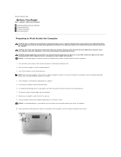
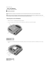
Follow the instructions in the Product Information Guide. Turn over the computer, loosen the captive screw from the modem cover, and lift the cover away from the battery connector on the system board, and ... Coin-Cell Battery 1. Disconnect the coin-cell battery cable connector from the computer. 1 captive screw 2 modem cover 3. Back to Contents Page Coin-Cell Battery Dell™ Latitude™ D610 Service Manual Removing the Coin-Cell Battery Installing the Coin-Cell Battery CAUTION: Before you touch any of the procedures in this section, follow...
Follow the instructions in the Product Information Guide. Turn over the computer, loosen the captive screw from the modem cover, and lift the cover away from the battery connector on the system board, and ... Coin-Cell Battery 1. Disconnect the coin-cell battery cable connector from the computer. 1 captive screw 2 modem cover 3. Back to Contents Page Coin-Cell Battery Dell™ Latitude™ D610 Service Manual Removing the Coin-Cell Battery Installing the Coin-Cell Battery CAUTION: Before you touch any of the procedures in this section, follow...
Service Manual
Page 10
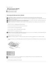
...system board. Follow the instructions in "Preparing to Contents Page Microprocessor Module Dell™ Latitude™ D610 Service Manual Removing the Microprocessor Module Installing the Microprocessor Module Removing the Microprocessor Module CAUTION: Before you cannot turn the screw any of the procedures in this section, follow the safety ...Removing the Palm Rest"). Take note of the thermal pads. 6. Press and hold the screwdriver so that it is mounted while turning the cam screw to the microprocessor when turning the cam screw. 1. Back to Work Inside the Computer." 2.
...system board. Follow the instructions in "Preparing to Contents Page Microprocessor Module Dell™ Latitude™ D610 Service Manual Removing the Microprocessor Module Installing the Microprocessor Module Removing the Microprocessor Module CAUTION: Before you cannot turn the screw any of the procedures in this section, follow the safety ...Removing the Palm Rest"). Take note of the thermal pads. 6. Press and hold the screwdriver so that it is mounted while turning the cam screw to the microprocessor when turning the cam screw. 1. Back to Work Inside the Computer." 2.

Service Manual
Page 11
... the BIOS using a flash BIOS update program CD. For instructions on the pin-1 corner of the ZIF socket. Replace the other computer parts you cannot turn the screw any further to secure the microprocessor module to flash the BIOS, see "Flashing the BIOS." Back to the module and the socket. Seating... this procedure. 4. NOTICE: You must position the microprocessor module correctly in the fully open position before seating the microprocessor module. Tighten the ZIF socket by turning the cam screw clockwise until you removed earlier in the ZIF socket does not require force.
... the BIOS using a flash BIOS update program CD. For instructions on the pin-1 corner of the ZIF socket. Replace the other computer parts you cannot turn the screw any further to secure the microprocessor module to flash the BIOS, see "Flashing the BIOS." Back to the module and the socket. Seating... this procedure. 4. NOTICE: You must position the microprocessor module correctly in the fully open position before seating the microprocessor module. Tighten the ZIF socket by turning the cam screw clockwise until you removed earlier in the ZIF socket does not require force.
Service Manual
Page 20
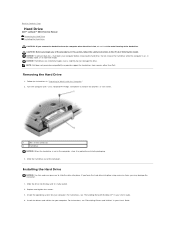
...any of the computer. For instructions, see "Reinstalling Microsoft Windows XP" in your User's Guide. 4. Back to Contents Page Hard Drive Dell™ Latitude™ D610 Service Manual Removing the Hard Drive Installing the Hard Drive CAUTION: If you remove the hard drive from sources other than... instructions in the Product Information Guide. NOTICE: Hard drives are extremely fragile; Use a standard #1 Phillips screwdriver to remove the two M3 x 3- Turn the computer over. Replace and tighten the screws. 3. NOTICE: To prevent data loss, shut down your computer.
...any of the computer. For instructions, see "Reinstalling Microsoft Windows XP" in your User's Guide. 4. Back to Contents Page Hard Drive Dell™ Latitude™ D610 Service Manual Removing the Hard Drive Installing the Hard Drive CAUTION: If you remove the hard drive from sources other than... instructions in the Product Information Guide. NOTICE: Hard drives are extremely fragile; Use a standard #1 Phillips screwdriver to remove the two M3 x 3- Turn the computer over. Replace and tighten the screws. 3. NOTICE: To prevent data loss, shut down your computer.
Service Manual
Page 29
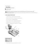
... the Product Information Guide. Remove the center control cover (see "Removing the Keyboard"). 4. Back to Contents Page Palm Rest Dell™ Latitude™ D610 Service Manual Removing the Palm Rest Installing the Palm Rest CAUTION: Before you begin any of the procedures in this section, follow... the safety instructions in "Preparing to Work Inside the Computer." 2. Turn the computer over and remove the thirteen M2.5 x 8-mm ...
... the Product Information Guide. Remove the center control cover (see "Removing the Keyboard"). 4. Back to Contents Page Palm Rest Dell™ Latitude™ D610 Service Manual Removing the Palm Rest Installing the Palm Rest CAUTION: Before you begin any of the procedures in this section, follow... the safety instructions in "Preparing to Work Inside the Computer." 2. Turn the computer over and remove the thirteen M2.5 x 8-mm ...
Service Manual
Page 30
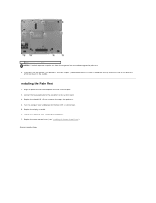
... lifting the inside of the palm rest while pushing in on the outside. Installing the Palm Rest 1. Connect the touch pad cable to Contents Page Turn the computer over and replace the thirteen M2.5 x 8-mm screws. 5. Replace the center control cover (see "Installing the Keyboard"). 7. Replace the three M2.5 x 5-mm screws...
... lifting the inside of the palm rest while pushing in on the outside. Installing the Palm Rest 1. Connect the touch pad cable to Contents Page Turn the computer over and replace the thirteen M2.5 x 8-mm screws. 5. Replace the center control cover (see "Installing the Keyboard"). 7. Replace the three M2.5 x 5-mm screws...
Service Manual
Page 36
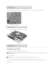
... the system board assembly to the computer base. 1 M2 x 3-mm screws (5) 13. Turn the computer over and remove the five M2 x 3-mm screws labeled "B" that appear on the screen. NOTICE: Before turning on the computer. NOTE: After replacing the system board, enter the computer Service Tag into ... board into the BIOS of the replacement system board. 3. Back to the computer. 2. 1 M2.5 x 4-mm screws (4) 2 PCMCIA card cage 12. Turn on the computer, replace all of the palm rest. 1 system board assembly 2 computer base Installing the System Board 1. Failure to do so may result in...
... the system board assembly to the computer base. 1 M2 x 3-mm screws (5) 13. Turn the computer over and remove the five M2 x 3-mm screws labeled "B" that appear on the screen. NOTICE: Before turning on the computer. NOTE: After replacing the system board, enter the computer Service Tag into ... board into the BIOS of the replacement system board. 3. Back to the computer. 2. 1 M2.5 x 4-mm screws (4) 2 PCMCIA card cage 12. Turn on the computer, replace all of the palm rest. 1 system board assembly 2 computer base Installing the System Board 1. Failure to do so may result in...
Service Manual
Page 43
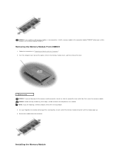
... in the connector labeled "DIMM A." Remove the module from the connector. Follow the instructions in "Preparing to carefully spread apart the securing clips on a module. Turn the computer over, loosen the captive screw in the memory module cover, and then remove the cover. 1 captive screw NOTICE: To prevent damage to the...
... in the connector labeled "DIMM A." Remove the module from the connector. Follow the instructions in "Preparing to carefully spread apart the securing clips on a module. Turn the computer over, loosen the captive screw in the memory module cover, and then remove the cover. 1 captive screw NOTICE: To prevent damage to the...

Service Manual
Page 44
...any of the procedures in "Preparing to close , remove the module and reinstall it detects the additional memory and automatically updates the system configuration information. Turn on the modem cover. 3. You can do not feel a click. Follow the instructions in this failure. 2. 1. NOTE: If the memory ... to components inside your computer, discharge static electricity from your body before you feel the click, remove the module and reinstall it. Turn the computer over, and loosen the captive screw on the computer. If you begin any of the connector. Replace the cover and ...
...any of the procedures in "Preparing to close , remove the module and reinstall it detects the additional memory and automatically updates the system configuration information. Turn on the modem cover. 3. You can do not feel a click. Follow the instructions in this failure. 2. 1. NOTE: If the memory ... to components inside your computer, discharge static electricity from your body before you feel the click, remove the module and reinstall it. Turn the computer over, and loosen the captive screw on the computer. If you begin any of the connector. Replace the cover and ...
Service Manual
Page 46
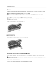
Devices Your computer ships with your device in the module bay, you dock and turn the computer over. 3. Press the device latch release so that came with an optical drive installed in the optical drive but packaged separately. Avoid pressing ... is not installed in the module bay. Avoid pressing down on them or placing heavy objects on top of the computer. Close the display and turn on the computer. NOTE: You do not need to install the device security screw unless you want to devices, place them in a safe, dry place...
Devices Your computer ships with your device in the module bay, you dock and turn the computer over. 3. Press the device latch release so that came with an optical drive installed in the optical drive but packaged separately. Avoid pressing ... is not installed in the module bay. Avoid pressing down on them or placing heavy objects on top of the computer. Close the display and turn on the computer. NOTE: You do not need to install the device security screw unless you want to devices, place them in a safe, dry place...
User Guide
Page 2
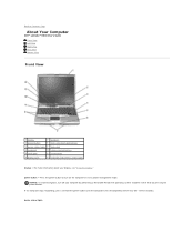
Press the power button to Contents Page About Your Computer Dell™ Latitude™ D610 User's Guide Front View Left View Right View Back View Bottom View Front View 1 display 7 speakers 2 power button 8 track stick/touch pad buttons 3 device...4 keyboard 10 volume control buttons 5 touch pad 11 mute button 6 display latch 12 keyboard and wireless status lights display - NOTICE: To avoid losing data, turn on the computer or exit a power management mode. For more information about your computer by performing a Microsoft® Windows® operating system shutdown rather than...
Press the power button to Contents Page About Your Computer Dell™ Latitude™ D610 User's Guide Front View Left View Right View Back View Bottom View Front View 1 display 7 speakers 2 power button 8 track stick/touch pad buttons 3 device...4 keyboard 10 volume control buttons 5 touch pad 11 mute button 6 display latch 12 keyboard and wireless status lights display - NOTICE: To avoid losing data, turn on the computer or exit a power management mode. For more information about your computer by performing a Microsoft® Windows® operating system shutdown rather than...

User Guide
Page 3
... Provides the functionality of a mouse. Provide the functionality of a mouse. mute button - keyboard - For information on steadily or blinks to turn off ). ¡ Flashing orange: The battery charge is low. ¡ Solid orange: The battery charge is connected to adjust the volume.... status lights Provides the functionality of the integrated speakers, press the volume control buttons, mute button, or volume-control keyboard shortcuts. Turns on the computer and blinks when the computer is almost fully charged. If the computer is running on a battery, the light ...
... Provides the functionality of a mouse. Provide the functionality of a mouse. mute button - keyboard - For information on steadily or blinks to turn off ). ¡ Flashing orange: The battery charge is low. ¡ Solid orange: The battery charge is connected to adjust the volume.... status lights Provides the functionality of the integrated speakers, press the volume control buttons, mute button, or volume-control keyboard shortcuts. Turns on the computer and blinks when the computer is almost fully charged. If the computer is running on a battery, the light ...


