System Information Guide
Page 14
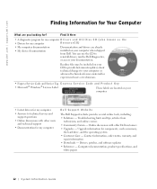
... website provides several online tools, including: • Solutions - You can use the CD to your documentation. Online discussion with other Dell customers • Upgrades - Upgrade information for ? www.dell.com | support.dell.com Finding Information for Your Computer What are located on your computer when shipped from technicians, and online courses • Community Forum - Troubleshooting...
... website provides several online tools, including: • Solutions - You can use the CD to your documentation. Online discussion with other Dell customers • Upgrades - Upgrade information for ? www.dell.com | support.dell.com Finding Information for Your Computer What are located on your computer when shipped from technicians, and online courses • Community Forum - Troubleshooting...
System Information Guide
Page 15
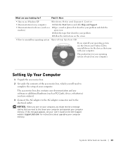
... computer memory. Setting Up Your Computer 1 Unpack the accessories box. 2 Set aside the contents of your computer memory. NOTICE: When you turn on the Dell Support website (support.dell.com) for the devices that you need to reinstall my operating system O p e r a t i n g S y s t e m C D If you ...have ordered. 3 Connect the AC adapter to the AC adapter connector and to shut down your computer and upgrade your computer. If this message appears, see ...
... computer memory. Setting Up Your Computer 1 Unpack the accessories box. 2 Set aside the contents of your computer memory. NOTICE: When you turn on the Dell Support website (support.dell.com) for the devices that you need to reinstall my operating system O p e r a t i n g S y s t e m C D If you ...have ordered. 3 Connect the AC adapter to the AC adapter connector and to shut down your computer and upgrade your computer. If this message appears, see ...
Service Manual
Page 11
...%20Manuals/Dell/Latitude/d600/upgrades.htm (1 of your computer's electronic components. Follow the instructions in "Preparing to components inside your Dell™ computer, read the safety instructions in your System Information Guide. Turn the computer over, loosen the captive screw from Dell are covered...an unpainted metal surface. Memory Module, Mini PCI Card, and Modules: Dell Latitude D600 Service Manual Back to Contents Page Memory Module, Mini PCI Card, and Modules Dell™ Latitude™ D600 Service Manual Memory Module Mini PCI Card Modules Memory Module CAUTION: Before...
...%20Manuals/Dell/Latitude/d600/upgrades.htm (1 of your computer's electronic components. Follow the instructions in "Preparing to components inside your Dell™ computer, read the safety instructions in your System Information Guide. Turn the computer over, loosen the captive screw from Dell are covered...an unpainted metal surface. Memory Module, Mini PCI Card, and Modules: Dell Latitude D600 Service Manual Back to Contents Page Memory Module, Mini PCI Card, and Modules Dell™ Latitude™ D600 Service Manual Memory Module Mini PCI Card Modules Memory Module CAUTION: Before...

Service Manual
Page 12
...by their edges, and do not use tools to spread the inner metal tabs that secure the memory module. 3. file:///F|/Service%20Manuals/Dell/Latitude/d600/upgrades.htm (2 of the memory module connector until the module pops up. Use your fingertips to carefully spread apart the securing clips on a module. ...If you are replacing a memory module, remove the existing module. b. Memory Module, Mini PCI Card, and Modules: Dell Latitude D600 Service Manual NOTICE: To prevent damage to the memory module connector, do not touch the components on each end of 10) [2/28/2004 8:15...
...by their edges, and do not use tools to spread the inner metal tabs that secure the memory module. 3. file:///F|/Service%20Manuals/Dell/Latitude/d600/upgrades.htm (2 of the memory module connector until the module pops up. Use your fingertips to carefully spread apart the securing clips on a module. ...If you are replacing a memory module, remove the existing module. b. Memory Module, Mini PCI Card, and Modules: Dell Latitude D600 Service Manual NOTICE: To prevent damage to the memory module connector, do not touch the components on each end of 10) [2/28/2004 8:15...

Service Manual
Page 13
Slide the edge of 10) [2/28/2004 8:15:43 AM] Replace the cover and screw. file:///F|/Service%20Manuals/Dell/Latitude/d600/upgrades.htm (3 of the module firmly into the connector, and rotate the module down until you feel the click, remove the module and reinstall it . ...NOTICE: If the memory module cover is not installed properly, the computer does not boot. Memory Module, Mini PCI Card, and Modules: Dell Latitude D600 Service Manual NOTICE: If you need to install memory modules in two connectors, install a memory module in the connector labeled "JDIM (Slot 1)" before you ...
Slide the edge of 10) [2/28/2004 8:15:43 AM] Replace the cover and screw. file:///F|/Service%20Manuals/Dell/Latitude/d600/upgrades.htm (3 of the module firmly into the connector, and rotate the module down until you feel the click, remove the module and reinstall it . ...NOTICE: If the memory module cover is not installed properly, the computer does not boot. Memory Module, Mini PCI Card, and Modules: Dell Latitude D600 Service Manual NOTICE: If you need to install memory modules in two connectors, install a memory module in the connector labeled "JDIM (Slot 1)" before you ...
Service Manual
Page 14
... Manual 6. As the computer boots, it detects the additional memory and automatically updates the system configuration information. file:///F|/Service%20Manuals/Dell/Latitude/d600/upgrades.htm (4 of your System Information Guide. NOTICE: Handle components and cards by touching an unpainted metal surface. Follow the instructions in your computer's ... the captive screw on the computer. Insert the battery into the battery bay, or connect the AC adapter to components inside your computer, Dell has already installed the card for you touch any of 10) [2/28/2004 8:15:43 AM]
... Manual 6. As the computer boots, it detects the additional memory and automatically updates the system configuration information. file:///F|/Service%20Manuals/Dell/Latitude/d600/upgrades.htm (4 of your System Information Guide. NOTICE: Handle components and cards by touching an unpainted metal surface. Follow the instructions in your computer's ... the captive screw on the computer. Insert the battery into the battery bay, or connect the AC adapter to components inside your computer, Dell has already installed the card for you touch any of 10) [2/28/2004 8:15:43 AM]
Service Manual
Page 15
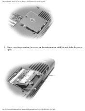
file:///F|/Service%20Manuals/Dell/Latitude/d600/upgrades.htm (5 of 10) [2/28/2004 8:15:43 AM] Memory Module, Mini PCI Card, and Modules: Dell Latitude D600 Service Manual 3. Place your finger under the cover at the indentation, and lift and slide the cover open.
file:///F|/Service%20Manuals/Dell/Latitude/d600/upgrades.htm (5 of 10) [2/28/2004 8:15:43 AM] Memory Module, Mini PCI Card, and Modules: Dell Latitude D600 Service Manual 3. Place your finger under the cover at the indentation, and lift and slide the cover open.

Service Manual
Page 16
... connector. 6. c. Connect the antenna cables from any attached cables. do not force the connections. 1 antenna cables file:///F|/Service%20Manuals/Dell/Latitude/d600/upgrades.htm (6 of its connector. 5. Memory Module, Mini PCI Card, and Modules: Dell Latitude D600 Service Manual 4. If a Mini PCI card is not already installed, go to the antenna connectors on the computer. If you...
... connector. 6. c. Connect the antenna cables from any attached cables. do not force the connections. 1 antenna cables file:///F|/Service%20Manuals/Dell/Latitude/d600/upgrades.htm (6 of its connector. 5. Memory Module, Mini PCI Card, and Modules: Dell Latitude D600 Service Manual 4. If a Mini PCI card is not already installed, go to the antenna connectors on the computer. If you...
Service Manual
Page 17
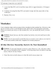
Memory Module, Mini PCI Card, and Modules: Dell Latitude D600 Service Manual 2 antenna connectors on top of them. 1. However, the device security screw is not installed in the module bay. NOTE: You do not need ... security screw unless you install your device in the computer. Press the device latch release so that the latch release pops out. file:///F|/Service%20Manuals/Dell/Latitude/d600/upgrades.htm (7 of the connector. 9. Modules Your computer ships with an optical drive installed in the optical drive but packaged separately. Lower the Mini PCI card...
Memory Module, Mini PCI Card, and Modules: Dell Latitude D600 Service Manual 2 antenna connectors on top of them. 1. However, the device security screw is not installed in the module bay. NOTE: You do not need ... security screw unless you install your device in the computer. Press the device latch release so that the latch release pops out. file:///F|/Service%20Manuals/Dell/Latitude/d600/upgrades.htm (7 of the connector. 9. Modules Your computer ships with an optical drive installed in the optical drive but packaged separately. Lower the Mini PCI card...
Service Manual
Page 18
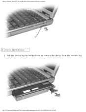
Memory Module, Mini PCI Card, and Modules: Dell Latitude D600 Service Manual 1 device latch release 2. file:///F|/Service%20Manuals/Dell/Latitude/d600/upgrades.htm (8 of 10) [2/28/2004 8:15:43 AM] Pull the device by the latch release to remove the device from the module bay.
Memory Module, Mini PCI Card, and Modules: Dell Latitude D600 Service Manual 1 device latch release 2. file:///F|/Service%20Manuals/Dell/Latitude/d600/upgrades.htm (8 of 10) [2/28/2004 8:15:43 AM] Pull the device by the latch release to remove the device from the module bay.

Service Manual
Page 19
... screw from the module bay. Close the display and turn the computer over. 3. See the documentation that the latch release pops out. 5. file:///F|/Service%20Manuals/Dell/Latitude/d600/upgrades.htm (9 of the computer. 1 M2 x 3-mm screw 7P786 4. If the computer is connected to devices, place them . 2. Use a #1 Phillips screwdriver to remove the device from...
... screw from the module bay. Close the display and turn the computer over. 3. See the documentation that the latch release pops out. 5. file:///F|/Service%20Manuals/Dell/Latitude/d600/upgrades.htm (9 of the computer. 1 M2 x 3-mm screw 7P786 4. If the computer is connected to devices, place them . 2. Use a #1 Phillips screwdriver to remove the device from...


