
Service Manual
Page 8
viii A prerequisite for troubleshooting procedures and instructions on using this manual to service Dell computer systems is a basic knowledge of your computer. Throughout this manual, Dell provides the User's Guide for using the Dell Diagnostics to information provided in this guide, blocks of text may be accompanied by an icon and printed in bold type or...
viii A prerequisite for troubleshooting procedures and instructions on using this manual to service Dell computer systems is a basic knowledge of your computer. Throughout this manual, Dell provides the User's Guide for using the Dell Diagnostics to information provided in this guide, blocks of text may be accompanied by an icon and printed in bold type or...
Service Manual
Page 9
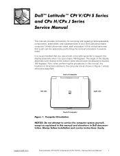
... the bottom case should never be replaced by performing the removal procedure in reverse order. The angle of computer support.dell.com Dell Latitude CPt V/CPt S Series and CPx H/CPx J Series Service Manual 1 Also, when performing the procedures in this manual assumes that you use a book or something similar to the computer are as shown in your...
... the bottom case should never be replaced by performing the removal procedure in reverse order. The angle of computer support.dell.com Dell Latitude CPt V/CPt S Series and CPx H/CPx J Series Service Manual 1 Also, when performing the procedures in this manual assumes that you use a book or something similar to the computer are as shown in your...
Service Manual
Page 10
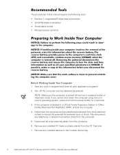
Save any attached peripherals from the computer. 6. Turn off and not in the modular device bay. 2 Dell Latitude CPt V/CPt S Series and CPx H/CPx J Series Service Manual Disconnect the computer and any work in this manual require the following tools: Number 1 magnetized Phillips-head screwdriver Small flat-blade screwdriver Small plastic scribe Microprocessor extractor 1. Disconnect all open...
Save any attached peripherals from the computer. 6. Turn off and not in the modular device bay. 2 Dell Latitude CPt V/CPt S Series and CPx H/CPx J Series Service Manual Disconnect the computer and any work in this manual require the following tools: Number 1 magnetized Phillips-head screwdriver Small flat-blade screwdriver Small plastic scribe Microprocessor extractor 1. Disconnect all open...
Service Manual
Page 11
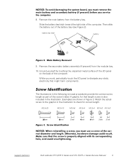
... assembly (if present) from the battery bay. M2.5x20 M2.5x10 M3.0x5 M2.5x4 M2.5x4 M3.0x3 M2.0x3 support.dell.com Dell Latitude CPt V/CPt S Series and CPx H/CPx J Series Service Manual 3 Ground yourself by touching the unpainted metal surface of the I /O panel to check for that might harm components. While you work...
... assembly (if present) from the battery bay. M2.5x20 M2.5x10 M3.0x5 M2.5x4 M2.5x4 M3.0x3 M2.0x3 support.dell.com Dell Latitude CPt V/CPt S Series and CPx H/CPx J Series Service Manual 3 Ground yourself by touching the unpainted metal surface of the I /O panel to check for that might harm components. While you work...
Service Manual
Page 12
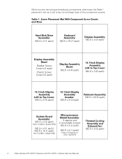
.... When you are removing and replacing components, photocopy the Table 1 placement mat as a tool to your system) Thermal Cooling Assembly and Exhaust Fan: M2.5 x 4 (2 each) 4 Dell Latitude CPt V/CPt S Series and CPx H/CPx J Series Service Manual
.... When you are removing and replacing components, photocopy the Table 1 placement mat as a tool to your system) Thermal Cooling Assembly and Exhaust Fan: M2.5 x 4 (2 each) 4 Dell Latitude CPt V/CPt S Series and CPx H/CPx J Series Service Manual
Service Manual
Page 13
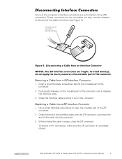
... sure the ZIF connector is completely closed. Use a small flat-blade screwdriver to disconnect the cable from them (see Figure 4). support.dell.com Dell Latitude CPt V/CPt S Series and CPx H/CPx J Series Service Manual 5 Some of the computer's interface connectors are not removable, but they must be released to open the movable part of the ZIF...
... sure the ZIF connector is completely closed. Use a small flat-blade screwdriver to disconnect the cable from them (see Figure 4). support.dell.com Dell Latitude CPt V/CPt S Series and CPx H/CPx J Series Service Manual 5 Some of the computer's interface connectors are not removable, but they must be released to open the movable part of the ZIF...
Service Manual
Page 14
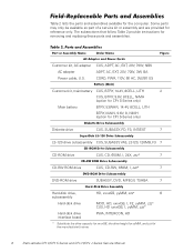
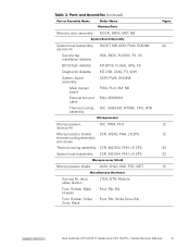
... of a service kit or assembly and are provided for the computer. The subsections that follow Table 2 provide instructions for the manufacturer's name. 6 Dell Latitude CPt V/CPt S Series and CPx H/CPx J Series Service Manual CUS, ADPT, AC, EXT, 20V, 70W, NBK ADPT, AC, EXT, 20V, 70W, 3W, BA CORD, PWR, 110V, 6F, AC, 3W.../3P, US Customer kit, main battery CUS, BTRY, 14.4V, 8CELL, LITH 2 CUS, BTRY, 9.6V, 8CELL, NiMH (option for CPt S-Series only) Main battery BTRY...
... of a service kit or assembly and are provided for the computer. The subsections that follow Table 2 provide instructions for the manufacturer's name. 6 Dell Latitude CPt V/CPt S Series and CPx H/CPx J Series Service Manual CUS, ADPT, AC, EXT, 20V, 70W, NBK ADPT, AC, EXT, 20V, 70W, 3W, BA CORD, PWR, 110V, 6F, AC, 3W.../3P, US Customer kit, main battery CUS, BTRY, 14.4V, 8CELL, LITH 2 CUS, BTRY, 9.6V, 8CELL, NiMH (option for CPt S-Series only) Main battery BTRY...
Service Manual
Page 15
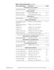
... 14.1-inch flex cable ASSY, CBL, FLX, TFT 12.1-inch flex cable ASSY, CBL, FLX, W/EXTN,12.1 14 14 16 16 14 16, 17 support.dell.com Dell Latitude CPt V/CPt S Series and CPx H/CPx J Series Service Manual 7
... 14.1-inch flex cable ASSY, CBL, FLX, TFT 12.1-inch flex cable ASSY, CBL, FLX, W/EXTN,12.1 14 14 16 16 14 16, 17 support.dell.com Dell Latitude CPt V/CPt S Series and CPx H/CPx J Series Service Manual 7

Service Manual
Page 16
...-MB CUS, 128MB, DIMM, SDRAM Customer kit, memory module, 192-MB CUS, 192MB, DIMM, SDRAM Customer kit, memory module, 256-MB CUS, 256MB, DIMM, SDRAM 8 Dell Latitude CPt V/CPt S Series and CPx H/CPx J Series Service Manual
...-MB CUS, 128MB, DIMM, SDRAM Customer kit, memory module, 192-MB CUS, 192MB, DIMM, SDRAM Customer kit, memory module, 256-MB CUS, 256MB, DIMM, SDRAM 8 Dell Latitude CPt V/CPt S Series and CPx H/CPx J Series Service Manual
Service Manual
Page 17
... Kit, latch, slider, Button Foot, Rubber, Black (4 each) Foot, Rubber, Strike Zone, Black LTCH, BTN, Module Foot, Rbr, Blk Foot, Rbr, Strike Zone, Blk support.dell.com Dell Latitude CPt V/CPt S Series and CPx H/CPx J Series Service Manual 9
... Kit, latch, slider, Button Foot, Rubber, Black (4 each) Foot, Rubber, Strike Zone, Black LTCH, BTN, Module Foot, Rbr, Blk Foot, Rbr, Strike Zone, Blk support.dell.com Dell Latitude CPt V/CPt S Series and CPx H/CPx J Series Service Manual 9
Service Manual
Page 18
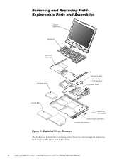
display assembly keyboard palmrest assembly hard-disk drive internal modem (may not apply to your system) system board main battery case plug for modem bottom case assembly modular bay device The following subsections provide instructions for removing and replacing field-replaceable parts and assemblies. 10 Dell Latitude CPt V/CPt S Series and CPx H/CPx J Series Service Manual
display assembly keyboard palmrest assembly hard-disk drive internal modem (may not apply to your system) system board main battery case plug for modem bottom case assembly modular bay device The following subsections provide instructions for removing and replacing field-replaceable parts and assemblies. 10 Dell Latitude CPt V/CPt S Series and CPx H/CPx J Series Service Manual
Service Manual
Page 19
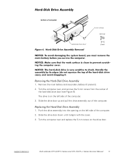
support.dell.com Dell Latitude CPt V/CPt S Series and CPx H/CPx J Series Service Manual 11 Remove the main battery and secondary battery (if present). 2. Push the drive assembly into the opening on the left side of the hard-disk ...
support.dell.com Dell Latitude CPt V/CPt S Series and CPx H/CPx J Series Service Manual 11 Remove the main battery and secondary battery (if present). 2. Push the drive assembly into the opening on the left side of the hard-disk ...
Service Manual
Page 20
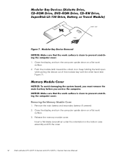
... down on a flat work surface. 3. Insert a flat-blade screwdriver under the indentation in the bottom case assembly and lift the cover. 12 Dell Latitude CPt V/CPt S Series and CPx H/CPx J Series Service Manual Close the display, and turn the computer upside down on a flat work surface. 2. Remove the main battery and secondary battery (if present...
... down on a flat work surface. 3. Insert a flat-blade screwdriver under the indentation in the bottom case assembly and lift the cover. 12 Dell Latitude CPt V/CPt S Series and CPx H/CPx J Series Service Manual Close the display, and turn the computer upside down on a flat work surface. 2. Remove the main battery and secondary battery (if present...
Service Manual
Page 21
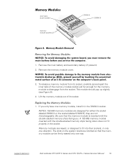
... the memory module is inserted with the double-stacked memory chips facing down does not fit properly in the DIMM A socket. support.dell.com Dell Latitude CPt V/CPt S Series and CPx H/CPx J Series Service Manual 13 Remove the main battery and secondary battery (if present). 2. Remove the memory module cover. 3. NOTES: 192-MB memory modules are...
... the memory module is inserted with the double-stacked memory chips facing down does not fit properly in the DIMM A socket. support.dell.com Dell Latitude CPt V/CPt S Series and CPx H/CPx J Series Service Manual 13 Remove the main battery and secondary battery (if present). 2. Remove the memory module cover. 3. NOTES: 192-MB memory modules are...
Service Manual
Page 22
... memory module's edge connector firmly into place. Pivot the memory module down on a flat work surface. 10-mm screws (7) M2.5x10 14 Dell Latitude CPt V/CPt S Series and CPx H/CPx J Series Service Manual If you do not hear a click as each end of the memory module socket. Close the display assembly, and turn the computer...
... memory module's edge connector firmly into place. Pivot the memory module down on a flat work surface. 10-mm screws (7) M2.5x10 14 Dell Latitude CPt V/CPt S Series and CPx H/CPx J Series Service Manual If you do not hear a click as each end of the memory module socket. Close the display assembly, and turn the computer...
Service Manual
Page 23
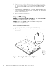
3. support.dell.com Dell Latitude CPt V/CPt S Series and CPx H/CPx J Series Service Manual 15 track stick keyboard scalloped edge of the keyboard. Release the keyboard from the palmrest assembly by inserting a small flat-blade screwdriver under the edge ...
3. support.dell.com Dell Latitude CPt V/CPt S Series and CPx H/CPx J Series Service Manual 15 track stick keyboard scalloped edge of the keyboard. Release the keyboard from the palmrest assembly by inserting a small flat-blade screwdriver under the edge ...
Service Manual
Page 24
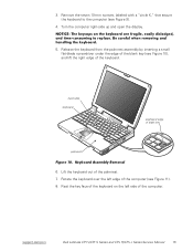
... on the left side of this cable is face down when you insert the cable into the keyboard ZIF interface connector. 16 Dell Latitude CPt V/CPt S Series and CPx H/CPx J Series Service Manual Remove the keyboard assembly. 1. Place the keyboard on the palmrest's flexible printed circuit board. 11. Connect the track stick cable to the...
... on the left side of this cable is face down when you insert the cable into the keyboard ZIF interface connector. 16 Dell Latitude CPt V/CPt S Series and CPx H/CPx J Series Service Manual Remove the keyboard assembly. 1. Place the keyboard on the palmrest's flexible printed circuit board. 11. Connect the track stick cable to the...

Service Manual
Page 25
... the left and right sides of the palmrest. 7. Carefully turn the keyboard over and reinstall the seven 10-mm screws. support.dell.com Dell Latitude CPt V/CPt S Series and CPx H/CPx J Series Service Manual 17 Carefully turn the computer over and fit the keyboard into the palmrest. 5. Start by installing the outermost screws on the blank...
... the left and right sides of the palmrest. 7. Carefully turn the keyboard over and reinstall the seven 10-mm screws. support.dell.com Dell Latitude CPt V/CPt S Series and CPx H/CPx J Series Service Manual 17 Carefully turn the computer over and fit the keyboard into the palmrest. 5. Start by installing the outermost screws on the blank...
Service Manual
Page 26
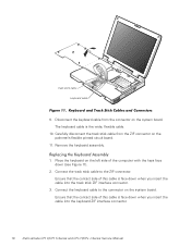
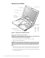
... the microprocessor module (see Figure 12). 4. 3-mm screws (2) microprocessor shield 4-mm screw (1) shield brace (may not apply to the microprocessor module. 18 Dell Latitude CPt V/CPt S Series and CPx H/CPx J Series Service Manual Remove the main battery and secondary battery (if present). 2. Remove the two 3-mm screws on the microprocessor board (2) microprocessor module captive screws...
... the microprocessor module (see Figure 12). 4. 3-mm screws (2) microprocessor shield 4-mm screw (1) shield brace (may not apply to the microprocessor module. 18 Dell Latitude CPt V/CPt S Series and CPx H/CPx J Series Service Manual Remove the main battery and secondary battery (if present). 2. Remove the two 3-mm screws on the microprocessor board (2) microprocessor module captive screws...
Service Manual
Page 27
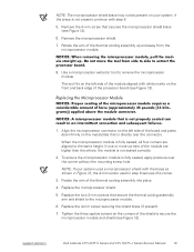
... securing the shield brace (if present). 7. Rotate the arm of the thermal cooling assembly up and away from the microprocessor module. 8. support.dell.com Dell Latitude CPt V/CPt S Series and CPx H/CPx J Series Service Manual 19 NOTE: If your system, if the brace is not seated correctly. 2. Replace the microprocessor shield. 5. If one or more corners...
... securing the shield brace (if present). 7. Rotate the arm of the thermal cooling assembly up and away from the microprocessor module. 8. support.dell.com Dell Latitude CPt V/CPt S Series and CPx H/CPx J Series Service Manual 19 NOTE: If your system, if the brace is not seated correctly. 2. Replace the microprocessor shield. 5. If one or more corners...


