
Service Manual
Page 9
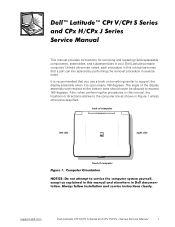
The angle of computer support.dell.com Dell Latitude CPt V/CPt S Series and CPx H/CPx J Series Service Manual 1 It is recommended that a part can be allowed to the computer are as shown in your Dell Latitude portable computer. back of computer left side right side front of the display assembly with respect to the bottom case should never be replaced...
The angle of computer support.dell.com Dell Latitude CPt V/CPt S Series and CPx H/CPx J Series Service Manual 1 It is recommended that a part can be allowed to the computer are as shown in your Dell Latitude portable computer. back of computer left side right side front of the display assembly with respect to the bottom case should never be replaced...
Service Manual
Page 10
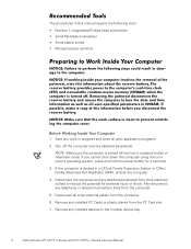
... blanks from the computer. 5. Also disconnect any work in suspend-to reduce the potential for 4 seconds. 3. The procedures in the modular device bay. 2 Dell Latitude CPt V/CPt S Series and CPx H/CPx J Series Service Manual Save any telephone or telecommunications lines from the PC Card slot. 7. Disconnect all open application programs. 2. Turn off and not in progress...
... blanks from the computer. 5. Also disconnect any work in suspend-to reduce the potential for 4 seconds. 3. The procedures in the modular device bay. 2 Dell Latitude CPt V/CPt S Series and CPx H/CPx J Series Service Manual Save any telephone or telecommunications lines from the PC Card slot. 7. Disconnect all open application programs. 2. Turn off and not in progress...
Service Manual
Page 11
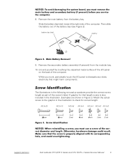
... provide the correct screw length as part of the computer. M2.5x20 M2.5x10 M3.0x5 M2.5x4 M2.5x4 M3.0x3 M2.0x3 support.dell.com Dell Latitude CPt V/CPt S Series and CPx H/CPx J Series Service Manual 3 Remove the main battery from the modular bay. 10. A graphic for correct length.
... provide the correct screw length as part of the computer. M2.5x20 M2.5x10 M3.0x5 M2.5x4 M2.5x4 M3.0x3 M2.0x3 support.dell.com Dell Latitude CPt V/CPt S Series and CPx H/CPx J Series Service Manual 3 Remove the main battery from the modular bay. 10. A graphic for correct length.
Service Manual
Page 12
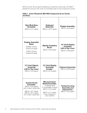
...) System Board Assembly: M2.5 x 4 (2 each) (w/o modem assembly) M2.5 x 4 (1 each) M2.5 x 10 (1 each) (w/ modem assembly) Microprocessor Shield Assembly: 3 captive and 2 removable screws M2.0 x 3 (2 each) M2.5 x 4 (1 each ) 4 Dell Latitude CPt V/CPt S Series and CPx H/CPx J Series Service Manual
...) System Board Assembly: M2.5 x 4 (2 each) (w/o modem assembly) M2.5 x 4 (1 each) M2.5 x 10 (1 each) (w/ modem assembly) Microprocessor Shield Assembly: 3 captive and 2 removable screws M2.0 x 3 (2 each) M2.5 x 4 (1 each ) 4 Dell Latitude CPt V/CPt S Series and CPx H/CPx J Series Service Manual
Service Manual
Page 13
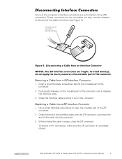
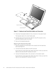
movable part of the connector. 2. Insert a small flat-blade screwdriver behind the movable part of connector (do not remove) 1. support.dell.com Dell Latitude CPt V/CPt S Series and CPx H/CPx J Series Service Manual 5 Orient the end of the interface cable with the ZIF connector, and insert the end of the connector. 1. Some of the computer's interface ...
movable part of the connector. 2. Insert a small flat-blade screwdriver behind the movable part of connector (do not remove) 1. support.dell.com Dell Latitude CPt V/CPt S Series and CPx H/CPx J Series Service Manual 5 Orient the end of the interface cable with the ZIF connector, and insert the end of the connector. 1. Some of the computer's interface ...
Service Manual
Page 14
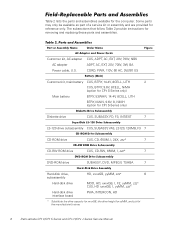
... Customer kit, main battery CUS, BTRY, 14.4V, 8CELL, LITH 2 CUS, BTRY, 9.6V, 8CELL, NiMH (option for CPt S-Series only) Main battery BTRY, 53WHR, 14.4V, 8CELL, LITH BTRY, MAIN, 9.6V, 8, NIMH (option for CPt S-Series only) Diskette drive CUS, SUBASSY, FD, F3, INT/EXT 7 LS-120 drive subassembly CUS, SUBASSY, VAS, LS120, 120MB... drive height for yyMM, and zzz for removing and replacing these parts and assemblies. The subsections that follow Table 2 provide instructions for the manufacturer's name. 6 Dell Latitude CPt V/CPt S Series and CPx H/CPx J Series Service Manual
... Customer kit, main battery CUS, BTRY, 14.4V, 8CELL, LITH 2 CUS, BTRY, 9.6V, 8CELL, NiMH (option for CPt S-Series only) Main battery BTRY, 53WHR, 14.4V, 8CELL, LITH BTRY, MAIN, 9.6V, 8, NIMH (option for CPt S-Series only) Diskette drive CUS, SUBASSY, FD, F3, INT/EXT 7 LS-120 drive subassembly CUS, SUBASSY, VAS, LS120, 120MB... drive height for yyMM, and zzz for removing and replacing these parts and assemblies. The subsections that follow Table 2 provide instructions for the manufacturer's name. 6 Dell Latitude CPt V/CPt S Series and CPx H/CPx J Series Service Manual
Service Manual
Page 15
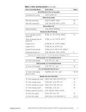
... 14.1-inch flex cable ASSY, CBL, FLX, TFT 12.1-inch flex cable ASSY, CBL, FLX, W/EXTN,12.1 14 14 16 16 14 16, 17 support.dell.com Dell Latitude CPt V/CPt S Series and CPx H/CPx J Series Service Manual 7
... 14.1-inch flex cable ASSY, CBL, FLX, TFT 12.1-inch flex cable ASSY, CBL, FLX, W/EXTN,12.1 14 14 16 16 14 16, 17 support.dell.com Dell Latitude CPt V/CPt S Series and CPx H/CPx J Series Service Manual 7

Service Manual
Page 16
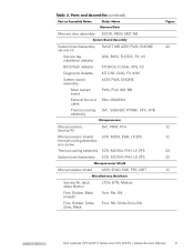
...-MB CUS, 128MB, DIMM, SDRAM Customer kit, memory module, 192-MB CUS, 192MB, DIMM, SDRAM Customer kit, memory module, 256-MB CUS, 256MB, DIMM, SDRAM 8 Dell Latitude CPt V/CPt S Series and CPx H/CPx J Series Service Manual
...-MB CUS, 128MB, DIMM, SDRAM Customer kit, memory module, 192-MB CUS, 192MB, DIMM, SDRAM Customer kit, memory module, 256-MB CUS, 256MB, DIMM, SDRAM 8 Dell Latitude CPt V/CPt S Series and CPx H/CPx J Series Service Manual
Service Manual
Page 17
... Kit, latch, slider, Button Foot, Rubber, Black (4 each) Foot, Rubber, Strike Zone, Black LTCH, BTN, Module Foot, Rbr, Blk Foot, Rbr, Strike Zone, Blk support.dell.com Dell Latitude CPt V/CPt S Series and CPx H/CPx J Series Service Manual 9
... Kit, latch, slider, Button Foot, Rubber, Black (4 each) Foot, Rubber, Strike Zone, Black LTCH, BTN, Module Foot, Rbr, Blk Foot, Rbr, Strike Zone, Blk support.dell.com Dell Latitude CPt V/CPt S Series and CPx H/CPx J Series Service Manual 9
Service Manual
Page 18
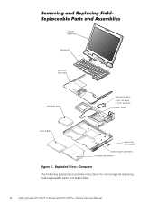
display assembly keyboard palmrest assembly hard-disk drive internal modem (may not apply to your system) system board main battery case plug for modem bottom case assembly modular bay device The following subsections provide instructions for removing and replacing field-replaceable parts and assemblies. 10 Dell Latitude CPt V/CPt S Series and CPx H/CPx J Series Service Manual
display assembly keyboard palmrest assembly hard-disk drive internal modem (may not apply to your system) system board main battery case plug for modem bottom case assembly modular bay device The following subsections provide instructions for removing and replacing field-replaceable parts and assemblies. 10 Dell Latitude CPt V/CPt S Series and CPx H/CPx J Series Service Manual
Service Manual
Page 19
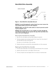
... secondary battery (if present). 2. Turn the computer over and replace the 5-mm screw on the left side of the computer. 2. bottom of the computer. 1. support.dell.com Dell Latitude CPt V/CPt S Series and CPx H/CPx J Series Service Manual 11
... secondary battery (if present). 2. Turn the computer over and replace the 5-mm screw on the left side of the computer. 2. bottom of the computer. 1. support.dell.com Dell Latitude CPt V/CPt S Series and CPx H/CPx J Series Service Manual 11
Service Manual
Page 20
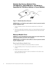
... the computer upside down on a flat work surface. 3. Insert a flat-blade screwdriver under the indentation in the bottom case assembly and lift the cover. 12 Dell Latitude CPt V/CPt S Series and CPx H/CPx J Series Service Manual
... the computer upside down on a flat work surface. 3. Insert a flat-blade screwdriver under the indentation in the bottom case assembly and lift the cover. 12 Dell Latitude CPt V/CPt S Series and CPx H/CPx J Series Service Manual
Service Manual
Page 21
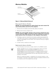
... for the memory module to fit into their sockets, in only one direction. The slots on the system board are not interchangeable. support.dell.com Dell Latitude CPt V/CPt S Series and CPx H/CPx J Series Service Manual 13 Remove the main battery and secondary battery (if present). 2. Lift the memory module out of the memory module socket just...
... for the memory module to fit into their sockets, in only one direction. The slots on the system board are not interchangeable. support.dell.com Dell Latitude CPt V/CPt S Series and CPx H/CPx J Series Service Manual 13 Remove the main battery and secondary battery (if present). 2. Lift the memory module out of the memory module socket just...
Service Manual
Page 22
... angle, press the memory module's edge connector firmly into place. Pivot the memory module down on a flat work surface. 10-mm screws (7) M2.5x10 14 Dell Latitude CPt V/CPt S Series and CPx H/CPx J Series Service Manual Remove the main battery and secondary battery (if present). 2. Replace the memory module cover. 1.
... angle, press the memory module's edge connector firmly into place. Pivot the memory module down on a flat work surface. 10-mm screws (7) M2.5x10 14 Dell Latitude CPt V/CPt S Series and CPx H/CPx J Series Service Manual Remove the main battery and secondary battery (if present). 2. Replace the memory module cover. 1.
Service Manual
Page 23
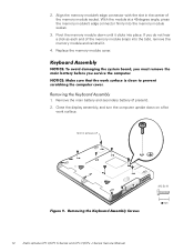
track stick keyboard scalloped edge of the palmrest. 7. support.dell.com Dell Latitude CPt V/CPt S Series and CPx H/CPx J Series Service Manual 15 Remove the seven 10-mm screws, labeled with a "circle K," that secure the keyboard to the computer (see Figure 10), and lift the ...
track stick keyboard scalloped edge of the palmrest. 7. support.dell.com Dell Latitude CPt V/CPt S Series and CPx H/CPx J Series Service Manual 15 Remove the seven 10-mm screws, labeled with a "circle K," that secure the keyboard to the computer (see Figure 10), and lift the ...
Service Manual
Page 24
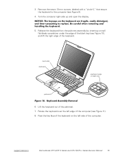
Ensure that the contact side of this cable is face down when you insert the cable into the keyboard ZIF interface connector. 16 Dell Latitude CPt V/CPt S Series and CPx H/CPx J Series Service Manual Disconnect the keyboard cable from the ZIF connector on the system board. Remove the keyboard assembly. 1. Connect the keyboard cable to the ZIF...
Ensure that the contact side of this cable is face down when you insert the cable into the keyboard ZIF interface connector. 16 Dell Latitude CPt V/CPt S Series and CPx H/CPx J Series Service Manual Disconnect the keyboard cable from the ZIF connector on the system board. Remove the keyboard assembly. 1. Connect the keyboard cable to the ZIF...

Service Manual
Page 25
Ensure that the keyboard is correctly installed. Carefully turn the keyboard over and reinstall the seven 10-mm screws. support.dell.com Dell Latitude CPt V/CPt S Series and CPx H/CPx J Series Service Manual 17 Check that the track stick and keyboard cables are not twisted as you lower the keyboard into place. 4. Start by installing the ...
Ensure that the keyboard is correctly installed. Carefully turn the keyboard over and reinstall the seven 10-mm screws. support.dell.com Dell Latitude CPt V/CPt S Series and CPx H/CPx J Series Service Manual 17 Check that the track stick and keyboard cables are not twisted as you lower the keyboard into place. 4. Start by installing the ...
Service Manual
Page 26
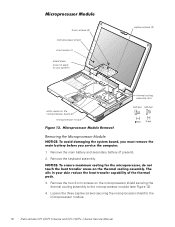
... screw (1) shield brace (may not apply to your system) white marks on the microprocessor shield securing the thermal cooling assembly to the microprocessor module. 18 Dell Latitude CPt V/CPt S Series and CPx H/CPx J Series Service Manual
... screw (1) shield brace (may not apply to your system) white marks on the microprocessor shield securing the thermal cooling assembly to the microprocessor module. 18 Dell Latitude CPt V/CPt S Series and CPx H/CPx J Series Service Manual
Service Manual
Page 27
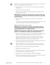
... corners are higher than the others, the module is not seated correctly. 2. Rotate the arm of the processor board (see Figure 12). 1. support.dell.com Dell Latitude CPt V/CPt S Series and CPx H/CPx J Series Service Manual 19 The tool fits on the left side of the module are aligned to remove the microprocessor module. If one or...
... corners are higher than the others, the module is not seated correctly. 2. Rotate the arm of the processor board (see Figure 12). 1. support.dell.com Dell Latitude CPt V/CPt S Series and CPx H/CPx J Series Service Manual 19 The tool fits on the left side of the module are aligned to remove the microprocessor module. If one or...
Service Manual
Page 28
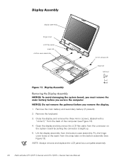
... flex cable snap tab bottom case assembly 4-mm screws (3) snap tab M2.5x4 1. NOTE: Always remove and replace the LCD panel as a complete assembly. 20 Dell Latitude CPt V/CPt S Series and CPx H/CPx J Series Service Manual
... flex cable snap tab bottom case assembly 4-mm screws (3) snap tab M2.5x4 1. NOTE: Always remove and replace the LCD panel as a complete assembly. 20 Dell Latitude CPt V/CPt S Series and CPx H/CPx J Series Service Manual


