
Service Manual
Page 2
... NT, and MS-DOS are registered trademarks of Intel Corporation; Dell Computer Corporation disclaims any proprietary interest in any manner whatsoever without notice. © 1994-1998 Dell Computer Corporation. A02 Information in this document to refer to change...Pentium are registered trademarks of International Business Machines Corporation. Trademarks used in this text: Dell, the DELL logo, and Latitude are registered trademarks and MMX is a registered trademark of Dell Computer Corporation; IBM is a trademark of Microsoft Corporation; All rights reserved. August...
... NT, and MS-DOS are registered trademarks of Intel Corporation; Dell Computer Corporation disclaims any proprietary interest in any manner whatsoever without notice. © 1994-1998 Dell Computer Corporation. A02 Information in this document to refer to change...Pentium are registered trademarks of International Business Machines Corporation. Trademarks used in this text: Dell, the DELL logo, and Latitude are registered trademarks and MMX is a registered trademark of Dell Computer Corporation; IBM is a trademark of Microsoft Corporation; All rights reserved. August...
Service Manual
Page 3
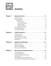
... 1-7 Initial User Contact 2-1 Visual Inspection 2-2 Observing the Boot Routine 2-4 Eliminating Resource Conflicts 2-6 Getting Help 2-6 POST Error Codes 3-1 Battery Failure Codes 3-4 System Error Messages 3-5 Running the Dell Diagnostics 3-9 Recommended Tools 4-2 Precautionary Measures 4-2 Screw Identification and Tightening 4-3 ZIF Connectors 4-4 Field-Replaceable Parts and Assemblies 4-5 Removing Field-Replaceable Parts and Assemblies 4-14 v
... 1-7 Initial User Contact 2-1 Visual Inspection 2-2 Observing the Boot Routine 2-4 Eliminating Resource Conflicts 2-6 Getting Help 2-6 POST Error Codes 3-1 Battery Failure Codes 3-4 System Error Messages 3-5 Running the Dell Diagnostics 3-9 Recommended Tools 4-2 Precautionary Measures 4-2 Screw Identification and Tightening 4-3 ZIF Connectors 4-4 Field-Replaceable Parts and Assemblies 4-5 Removing Field-Replaceable Parts and Assemblies 4-14 v
Service Manual
Page 4
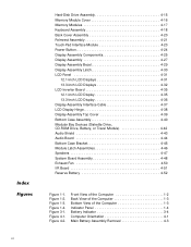
Figure 3-1. Figure 4-2. Hard-Disk Drive Assembly 4-15 Memory Module Cover 4-16 Memory Modules 4-17 Keyboard Assembly 4-18 Back Cover Assembly 4-20 Palmrest Assembly 4-21 Touch-Pad Interface Module 4-23 Power Button 4-24 Display Assembly Components 4-25 Display Assembly 4-27 Display Assembly Bezel 4-29 Display Assembly Latch 4-30 LCD Panel 4-31 12.1-Inch LCD Displays 4-31 13.3-Inch LCD Displays 4-32 LCD Inverter Board 4-35 12.1-Inch LCD Display 4-35 13.3-Inch LCD Display 4-36 Display-Assembly Interface Cable 4-37 LCD Display Hinge 4-38 Display-Assembly Top Cover ...
Figure 3-1. Figure 4-2. Hard-Disk Drive Assembly 4-15 Memory Module Cover 4-16 Memory Modules 4-17 Keyboard Assembly 4-18 Back Cover Assembly 4-20 Palmrest Assembly 4-21 Touch-Pad Interface Module 4-23 Power Button 4-24 Display Assembly Components 4-25 Display Assembly 4-27 Display Assembly Bezel 4-29 Display Assembly Latch 4-30 LCD Panel 4-31 12.1-Inch LCD Displays 4-31 13.3-Inch LCD Displays 4-32 LCD Inverter Board 4-35 12.1-Inch LCD Display 4-35 13.3-Inch LCD Display 4-36 Display-Assembly Interface Cable 4-37 LCD Display Hinge 4-38 Display-Assembly Top Cover ...
Service Manual
Page 5
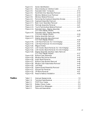
Figure 4-9. Figure 4-13. Figure 4-15. Figure 4-18. Figure 4-19. Figure 4-26. Figure 4-28. Table 3-3. Interrupt Assignments 1-6 Technical Specifications 1-7 POST Error Codes 3-2 Battery Failure Codes 3-4 System Error Messages 3-5 Parts and Assemblies 4-5 vii Figure 4-4. Figure 4-20. Figure 4-22. Screw Identification 4-3 Disconnecting an Interface Cable 4-4 Exploded View-Computer 4-14 Hard-Disk Drive Assembly Removal 4-15 Memory Module Cover Removal 4-16 Memory Module Removal 4-17 Removing the Keyboard Assembly Screws 4-18 Keyboard Assembly Removal 4-19 Back ...
Figure 4-9. Figure 4-13. Figure 4-15. Figure 4-18. Figure 4-19. Figure 4-26. Figure 4-28. Table 3-3. Interrupt Assignments 1-6 Technical Specifications 1-7 POST Error Codes 3-2 Battery Failure Codes 3-4 System Error Messages 3-5 Parts and Assemblies 4-5 vii Figure 4-4. Figure 4-20. Figure 4-22. Screw Identification 4-3 Disconnecting an Interface Cable 4-4 Exploded View-Computer 4-14 Hard-Disk Drive Assembly Removal 4-15 Memory Module Cover Removal 4-16 Memory Module Removal 4-17 Removing the Keyboard Assembly Screws 4-18 Keyboard Assembly Removal 4-19 Back ...
Service Manual
Page 6
...manual, there may be blocks of IBM®-compatible PCs and prior training in italic type. viii Throughout this manual to service Dell computer systems is a basic knowledge of text printed in bold type or in IBM-compatible PC troubleshooting techniques. A prerequisite for ...troubleshooting procedures and instructions on using the Dell diagnostics to test the computer system. These blocks are warnings, cautions, and notes, and they are used as follows: NOTE: A NOTE...
...manual, there may be blocks of IBM®-compatible PCs and prior training in italic type. viii Throughout this manual to service Dell computer systems is a basic knowledge of text printed in bold type or in IBM-compatible PC troubleshooting techniques. A prerequisite for ...troubleshooting procedures and instructions on using the Dell diagnostics to test the computer system. These blocks are warnings, cautions, and notes, and they are used as follows: NOTE: A NOTE...
Service Manual
Page 7
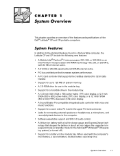
.... When used with a built-in charge gauge and ExpressCharge technology that charges the battery in about an hour (when the computer is in a Dell portable computer, the Latitude CP and CPi include the following new features: A Mobile Intel® Pentium® II microprocessor 233, 266, or 300 MHz or an Intel Pentium microprocessor... of the features and specifications of system memory. Support for connecting external speakers or headphones, a microphone, and record/playback devices to 128 MB of the Dell® Latitude® CP and CPi portable computers.
.... When used with a built-in charge gauge and ExpressCharge technology that charges the battery in about an hour (when the computer is in a Dell portable computer, the Latitude CP and CPi include the following new features: A Mobile Intel® Pentium® II microprocessor 233, 266, or 300 MHz or an Intel Pentium microprocessor... of the features and specifications of system memory. Support for connecting external speakers or headphones, a microphone, and record/playback devices to 128 MB of the Dell® Latitude® CP and CPi portable computers.
Service Manual
Page 8
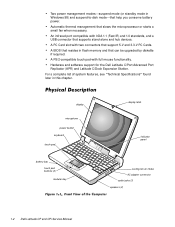
Automatic thermal management that help you conserve battery power. Hardware and software support for the Dell Latitude C/Port Advanced Port Replicator (APR) and Latitude C/Dock Expansion Station. An infrared port compatible with two connectors that support 5-V and 3.3-V PC Cards. A PC Card ...pad buttons (2) modular bay display latch indicator panel cooling-fan air intake AC adapter connector audio jacks (3) speakers (2) 1-2 Dell Latitude CP and CPi Service Manual A PS/2-compatible touch pad with full mouse functionality. For a complete list of system features, see "Technical ...
Automatic thermal management that help you conserve battery power. Hardware and software support for the Dell Latitude C/Port Advanced Port Replicator (APR) and Latitude C/Dock Expansion Station. An infrared port compatible with two connectors that support 5-V and 3.3-V PC Cards. A PC Card ...pad buttons (2) modular bay display latch indicator panel cooling-fan air intake AC adapter connector audio jacks (3) speakers (2) 1-2 Dell Latitude CP and CPi Service Manual A PS/2-compatible touch pad with full mouse functionality. For a complete list of system features, see "Technical ...
Service Manual
Page 9
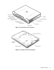
fan outlet parallel connector USB connector docking connector door docking connector serial connector monitor connector PS2 connector infrared port speaker security cable slot hard-disk drive PC Card slot modular bay latch battery bay latch memory module cover hard-disk drive System Overview 1-3
fan outlet parallel connector USB connector docking connector door docking connector serial connector monitor connector PS2 connector infrared port speaker security cable slot hard-disk drive PC Card slot modular bay latch battery bay latch memory module cover hard-disk drive System Overview 1-3
Service Manual
Page 10
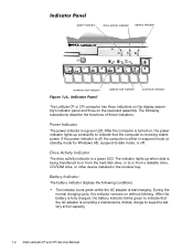
power indicator drive activity indicator battery indicator numbers lock indicator capitals lock indicator scroll lock indicator The Latitude CP or CPi computer has three indicators on the display assembly's indicator panel and three on without blinking. If the power indicator is off . The power indicator is ... indicator turns green while the AC adapter is being transferred to or from the hard-disk drive, or to keep the battery at full capacity. 1-4 Dell Latitude CP and CPi Service Manual
power indicator drive activity indicator battery indicator numbers lock indicator capitals lock indicator scroll lock indicator The Latitude CP or CPi computer has three indicators on the display assembly's indicator panel and three on without blinking. If the power indicator is off . The power indicator is ... indicator turns green while the AC adapter is being transferred to or from the hard-disk drive, or to keep the battery at full capacity. 1-4 Dell Latitude CP and CPi Service Manual
Service Manual
Page 11
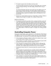
These indicators are as follows: If the computer is off (power indicator is on the Latitude CP or CPi computer, C/Dock Expansion Station, or the C/Port APR initiates a change from -disk operation. Pressing the power button on ) and the display is open but off ) ...and the display is open or an external monitor is attached, pressing the power button on the Latitude C/Port APR or C/Dock Expansion Station has...
These indicators are as follows: If the computer is off (power indicator is on the Latitude CP or CPi computer, C/Dock Expansion Station, or the C/Port APR initiates a change from -disk operation. Pressing the power button on ) and the display is open but off ) ...and the display is open or an external monitor is attached, pressing the power button on the Latitude C/Port APR or C/Dock Expansion Station has...
Service Manual
Page 12
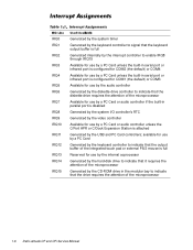
... C/Port APR or C/Dock Expansion Station is attached Generated by the keyboard controller to signal that the diskette drive requires the attention of the microprocessor 1-6 Dell Latitude CP and CPi Service Manual
... C/Port APR or C/Dock Expansion Station is attached Generated by the keyboard controller to signal that the diskette drive requires the attention of the microprocessor 1-6 Dell Latitude CP and CPi Service Manual
Service Manual
Page 13
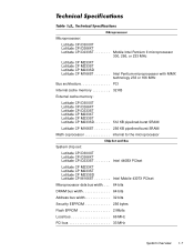
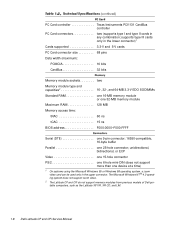
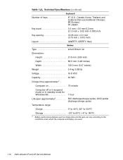
... KB External cache memory: Latitude CPi D300XT Latitude CPi D266XT Latitude CPi D233ST Latitude CP M233XT Latitude CP M233ST Latitude CP M233SD 512 KB pipelined-burst SRAM Latitude CP M166ST 256 KB pipelined-burst SRAM Math coprocessor internal to the microprocessor System chip set: Latitude CPi D300XT Latitude CPi D266XT Latitude CPi D233ST Intel 440BX PCIset Latitude CP M233XT Latitude CP M233ST Latitude CP M233SD Latitude CP M166ST Intel Mobile...
... KB External cache memory: Latitude CPi D300XT Latitude CPi D266XT Latitude CPi D233ST Latitude CP M233XT Latitude CP M233ST Latitude CP M233SD 512 KB pipelined-burst SRAM Latitude CP M166ST 256 KB pipelined-burst SRAM Math coprocessor internal to the microprocessor System chip set: Latitude CPi D300XT Latitude CPi D266XT Latitude CPi D233ST Intel 440BX PCIset Latitude CP M233XT Latitude CP M233ST Latitude CP M233SD Latitude CP M166ST Intel Mobile...
Service Manual
Page 14
... mini-DIN (does not support more than one 25-hole connector; The Microsoft Windows NT ® 4.0 operating system does not support zoom video. 2 The Latitude CP and CPi do not support memory modules from previous models of Dell portable computers, such as the Latitude XP, XPi, XPi CD, and LM. 1-8 Dell Latitude CP and CPi Service Manual
... mini-DIN (does not support more than one 25-hole connector; The Microsoft Windows NT ® 4.0 operating system does not support zoom video. 2 The Latitude CP and CPi do not support memory modules from previous models of Dell portable computers, such as the Latitude XP, XPi, XPi CD, and LM. 1-8 Dell Latitude CP and CPi Service Manual
Service Manual
Page 15
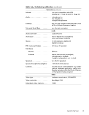
...-operator Interfaces: Internal ISA bus External stereo line-in/audio-in minijack; line-in/audio-in minijack; headphones/speakers Docking one 200-pin connector for Latitude C/Port APR or C/Dock Expansion Station Universal Serial Bus one port compatible with key combinations, software application menus, the Speaker window in the...
...-operator Interfaces: Internal ISA bus External stereo line-in/audio-in minijack; line-in/audio-in minijack; headphones/speakers Docking one 200-pin connector for Latitude C/Port APR or C/Dock Expansion Station Universal Serial Bus one port compatible with key combinations, software application menus, the Speaker window in the...
Service Manual
Page 16
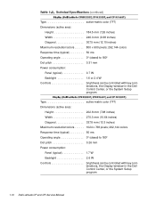
...pitch 0.31 mm Power consumption: Panel (typical 0.7 W Backlight 1.6 or 2.4 W Controls brightness can be controlled with key combinations, the Display window in the Dell Control Center, or the System Setup program Type active-matrix color (TFT) Dimensions (active area): Height 202.8 mm (7.98 inches) Width 270.3 mm (10...Dot pitch 0.26 mm Power consumption: Panel (typical 1.7 W Backlight 2.6 W Controls brightness can be controlled with key combinations, the Display window in the Dell Control Center, or the System Setup program 1-10 Dell Latitude CP and CPi Service Manual
...pitch 0.31 mm Power consumption: Panel (typical 0.7 W Backlight 1.6 or 2.4 W Controls brightness can be controlled with key combinations, the Display window in the Dell Control Center, or the System Setup program Type active-matrix color (TFT) Dimensions (active area): Height 202.8 mm (7.98 inches) Width 270.3 mm (10...Dot pitch 0.26 mm Power consumption: Panel (typical 1.7 W Backlight 2.6 W Controls brightness can be controlled with key combinations, the Display window in the Dell Control Center, or the System Setup program 1-10 Dell Latitude CP and CPi Service Manual
Service Manual
Page 17
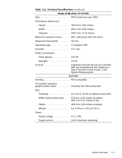
...; Dot pitch 0.31 mm Power consumption: Panel (typical 0.63 W Backlight 3.2 W Controls brightness and contrast can be controlled with key combinations, the Display window in the Dell Control Center, or the System Setup program Interface PS/2-compatible X/Y position resolution (graphics table mode 20 points/mm (500 points/inch) Size: Thickness 2.5 mm (0.10...
...; Dot pitch 0.31 mm Power consumption: Panel (typical 0.63 W Backlight 3.2 W Controls brightness and contrast can be controlled with key combinations, the Display window in the Dell Control Center, or the System Setup program Interface PS/2-compatible X/Y position resolution (graphics table mode 20 points/mm (500 points/inch) Size: Thickness 2.5 mm (0.10...
Service Manual
Page 18
...;F) 3 Battery performance features such as charge time and life span can vary according to the conditions under which the computer and battery are used. 1-12 Dell Latitude CP and CPi Service Manual
...;F) 3 Battery performance features such as charge time and life span can vary according to the conditions under which the computer and battery are used. 1-12 Dell Latitude CP and CPi Service Manual
Service Manual
Page 19
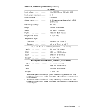
Your computer might weigh more or less, depending on its configuration. 5 Weight shown is with a hard-disk drive, a battery in the battery bay, a diskette drive in the modular bay, and one memory module. Input voltage 90 to 135 VAC and 164 to 264 VAC Input current (maximum 3.5 A Input frequency 47 to 63 Hz Output current 4.5 A (maximum at 4-sec pulse); 3.51 A (continuous) Rated output voltage 20.0 VDC Height 27.9 mm (1.09 inches) Width 58.4 mm (2.29 inches) Depth 133.3 mm (5.25 inches) Weight (with cables 0.4 kg (0.9 lb) Temperature range: Operating 0° to 40°C (...
Your computer might weigh more or less, depending on its configuration. 5 Weight shown is with a hard-disk drive, a battery in the battery bay, a diskette drive in the modular bay, and one memory module. Input voltage 90 to 135 VAC and 164 to 264 VAC Input current (maximum 3.5 A Input frequency 47 to 63 Hz Output current 4.5 A (maximum at 4-sec pulse); 3.51 A (continuous) Rated output voltage 20.0 VDC Height 27.9 mm (1.09 inches) Width 58.4 mm (2.29 inches) Depth 133.3 mm (5.25 inches) Weight (with cables 0.4 kg (0.9 lb) Temperature range: Operating 0° to 40°C (...
Service Manual
Page 20
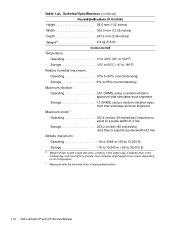
... more or less, depending on its configuration. 7 Measured with a hard-disk drive, a battery in the battery bay, a diskette drive in head-parked position. 1-14 Dell Latitude CP and CPi Service Manual Height 38.6 mm (1.52 inches) Width 306.0 mm (12.05 inches) Depth 241.0 mm (9.49 inches) Weight6 2.6 kg (5.8 lb) Temperature: Operating 0°...
... more or less, depending on its configuration. 7 Measured with a hard-disk drive, a battery in the battery bay, a diskette drive in head-parked position. 1-14 Dell Latitude CP and CPi Service Manual Height 38.6 mm (1.52 inches) Width 306.0 mm (12.05 inches) Depth 241.0 mm (9.49 inches) Weight6 2.6 kg (5.8 lb) Temperature: Operating 0°...
Service Manual
Page 21
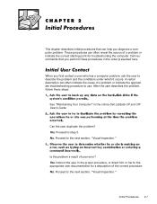
..., "Visual Inspection." Proceed to the appropriate user documentation for troubleshooting the computer. After the user describes the problem, follow these procedures in the online Dell Latitude CP and CPi User's Guide. Yes. This chapter describes initial procedures that you perform these steps: See "Maintaining Your Computer" in the order presented here. A verbal description...
..., "Visual Inspection." Proceed to the appropriate user documentation for troubleshooting the computer. After the user describes the problem, follow these procedures in the online Dell Latitude CP and CPi User's Guide. Yes. This chapter describes initial procedures that you perform these steps: See "Maintaining Your Computer" in the order presented here. A verbal description...
