Service Manual
Page 4
... View of the Computer 1-3 Indicator Panel 1-4 Battery Indicator 3-4 Computer Orientation 4-1 Main Battery Assembly Removal 4-3 vi Figure 4-2. Figure 1-4. Hard-Disk Drive Assembly 4-15 Memory Module Cover 4-16 Memory Modules 4-17 Keyboard Assembly 4-18 Back Cover Assembly 4-20 Palmrest Assembly 4-21 Touch-Pad ...Cable 4-37 LCD Display Hinge 4-38 Display-Assembly Top Cover 4-39 Bottom Case Assembly 4-40 Modular Bay Devices (Diskette Drive, CD-ROM Drive, Battery, or Travel Module 4-42 Audio Shield 4-43 Audio Board 4-44 Bottom Case Bracket 4-45 Module Latch Assemblies...
... View of the Computer 1-3 Indicator Panel 1-4 Battery Indicator 3-4 Computer Orientation 4-1 Main Battery Assembly Removal 4-3 vi Figure 4-2. Figure 1-4. Hard-Disk Drive Assembly 4-15 Memory Module Cover 4-16 Memory Modules 4-17 Keyboard Assembly 4-18 Back Cover Assembly 4-20 Palmrest Assembly 4-21 Touch-Pad ...Cable 4-37 LCD Display Hinge 4-38 Display-Assembly Top Cover 4-39 Bottom Case Assembly 4-40 Modular Bay Devices (Diskette Drive, CD-ROM Drive, Battery, or Travel Module 4-42 Audio Shield 4-43 Audio Board 4-44 Bottom Case Bracket 4-45 Module Latch Assemblies...
Service Manual
Page 5
.... Figure 4-12. Table 3-3. Figure 4-10. Figure 4-28. Figure 4-5. Figure 4-7. Figure 4-3. Figure 4-23. Figure 4-27. Screw Identification 4-3 Disconnecting an Interface Cable 4-4 Exploded View-Computer 4-14 Hard-Disk Drive Assembly Removal 4-15 Memory Module Cover Removal 4-16 Memory Module Removal 4-17 Removing the Keyboard Assembly Screws 4-18 Keyboard Assembly Removal 4-19 Back Cover Assembly...
.... Figure 4-12. Table 3-3. Figure 4-10. Figure 4-28. Figure 4-5. Figure 4-7. Figure 4-3. Figure 4-23. Figure 4-27. Screw Identification 4-3 Disconnecting an Interface Cable 4-4 Exploded View-Computer 4-14 Hard-Disk Drive Assembly Removal 4-15 Memory Module Cover Removal 4-16 Memory Module Removal 4-17 Removing the Keyboard Assembly Screws 4-18 Keyboard Assembly Removal 4-19 Back Cover Assembly...
Service Manual
Page 7
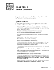
... CPi portable computers. This chapter provides an overview of the features and specifications of internal cache. Jacks for a battery in a Dell portable computer, the Latitude CP and CPi include the following new features: A Mobile Intel® Pentium® II microprocessor 233, 266, or 300 MHz or ...System Overview 1-1 PCI bus architecture that charges the battery in about an hour (when the computer is in suspend mode [or standby mode for a hard-disk drive in the modular bay. Support for the Microsoft® Windows® 98 operating system] or turned off). A 13.3-inch XGA (1024 x ...
... CPi portable computers. This chapter provides an overview of the features and specifications of internal cache. Jacks for a battery in a Dell portable computer, the Latitude CP and CPi include the following new features: A Mobile Intel® Pentium® II microprocessor 233, 266, or 300 MHz or ...System Overview 1-1 PCI bus architecture that charges the battery in about an hour (when the computer is in suspend mode [or standby mode for a hard-disk drive in the modular bay. Support for the Microsoft® Windows® 98 operating system] or turned off). A 13.3-inch XGA (1024 x ...
Service Manual
Page 9
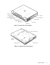
fan outlet parallel connector USB connector docking connector door docking connector serial connector monitor connector PS2 connector infrared port speaker security cable slot hard-disk drive PC Card slot modular bay latch battery bay latch memory module cover hard-disk drive System Overview 1-3
fan outlet parallel connector USB connector docking connector door docking connector serial connector monitor connector PS2 connector infrared port speaker security cable slot hard-disk drive PC Card slot modular bay latch battery bay latch memory module cover hard-disk drive System Overview 1-3
Service Manual
Page 10
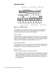
...following conditions: The indicator turns green while the AC adapter is being transferred to or from the hard-disk drive, or to or from a diskette drive, CD-ROM drive, or other device installed in suspend mode (or standby mode for Windows 98), suspend-to indicate ... (trickle) charge to keep the battery at full capacity. 1-4 Dell Latitude CP and CPi Service Manual power indicator drive activity indicator battery indicator numbers lock indicator capitals lock indicator scroll lock indicator The Latitude CP or CPi computer has three indicators on the display assembly's indicator ...
...following conditions: The indicator turns green while the AC adapter is being transferred to or from the hard-disk drive, or to or from a diskette drive, CD-ROM drive, or other device installed in suspend mode (or standby mode for Windows 98), suspend-to indicate ... (trickle) charge to keep the battery at full capacity. 1-4 Dell Latitude CP and CPi Service Manual power indicator drive activity indicator battery indicator numbers lock indicator capitals lock indicator scroll lock indicator The Latitude CP or CPi computer has three indicators on the display assembly's indicator ...
Service Manual
Page 12
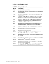
...full Reserved for use by the internal coprocessor Generated by the hard-disk drive to indicate that it requires the attention of the microprocessor Generated by the CD-ROM drive in the modular bay to indicate that the drive requires the attention of the microprocessor Available for use by a...use by a PC Card unless the built-in parallel port is attached Generated by the diskette drive controller to indicate that the diskette drive requires the attention of the microprocessor 1-6 Dell Latitude CP and CPi Service Manual IRQ0 IRQ1 IRQ2 IRQ3 IRQ4 IRQ5 IRQ6 IRQ7 IRQ8 IRQ9 IRQ10 IRQ11 IRQ12...
...full Reserved for use by the internal coprocessor Generated by the hard-disk drive to indicate that it requires the attention of the microprocessor Generated by the CD-ROM drive in the modular bay to indicate that the drive requires the attention of the microprocessor Available for use by a...use by a PC Card unless the built-in parallel port is attached Generated by the diskette drive controller to indicate that the diskette drive requires the attention of the microprocessor 1-6 Dell Latitude CP and CPi Service Manual IRQ0 IRQ1 IRQ2 IRQ3 IRQ4 IRQ5 IRQ6 IRQ7 IRQ8 IRQ9 IRQ10 IRQ11 IRQ12...
Service Manual
Page 19
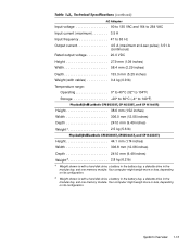
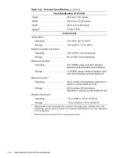
... or less, depending on its configuration. Your computer might weigh more or less, depending on its configuration. 5 Weight shown is with a hard-disk drive, a battery in the battery bay, a diskette drive in the modular bay, and one memory module. Input voltage 90 to 135 VAC and 164 to 264 VAC Input current (maximum... 2.5 kg (5.6 lb) Height 44.1 mm (1.74 inches) Width 306.8 mm (12.08 inches) Depth 241.0 mm (9.49 inches) Weight5 2.8 kg (6.2 lb) 4 Weight shown is with a hard-disk drive, a battery in the battery bay, a diskette drive in the modular bay, and one memory module.
... or less, depending on its configuration. Your computer might weigh more or less, depending on its configuration. 5 Weight shown is with a hard-disk drive, a battery in the battery bay, a diskette drive in the modular bay, and one memory module. Input voltage 90 to 135 VAC and 164 to 264 VAC Input current (maximum... 2.5 kg (5.6 lb) Height 44.1 mm (1.74 inches) Width 306.8 mm (12.08 inches) Depth 241.0 mm (9.49 inches) Weight5 2.8 kg (6.2 lb) 4 Weight shown is with a hard-disk drive, a battery in the battery bay, a diskette drive in the modular bay, and one memory module.
Service Manual
Page 20
Your computer might weigh more or less, depending on its configuration. 7 Measured with a hard-disk drive, a battery in the battery bay, a diskette drive in head-parked position. 1-14 Dell Latitude CP and CPi Service Manual Height 38.6 mm (1.52 inches) Width 306.0 mm (12.05 inches) Depth 241.0 mm (9.49 inches) Weight6 2.6 kg (5.8 lb) Temperature: Operating 0&#... (maximum): Operating 18 to 3048 m (-59 to 10,000 ft) Storage 18 to 10,600 m (-59 to 35,000 ft) 6 Weight shown is with the hard-disk drive in the modular bay, and one memory module.
Your computer might weigh more or less, depending on its configuration. 7 Measured with a hard-disk drive, a battery in the battery bay, a diskette drive in head-parked position. 1-14 Dell Latitude CP and CPi Service Manual Height 38.6 mm (1.52 inches) Width 306.0 mm (12.05 inches) Depth 241.0 mm (9.49 inches) Weight6 2.6 kg (5.8 lb) Temperature: Operating 0&#... (maximum): Operating 18 to 3048 m (-59 to 10,000 ft) Storage 18 to 10,600 m (-59 to 35,000 ft) 6 Weight shown is with the hard-disk drive in the modular bay, and one memory module.
Service Manual
Page 25
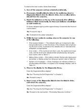
...subsystem. Error codes - System error messages - Proceed to light during the boot routine, refer to Table 3-1. Yes. See "Running the Dell Diagnostics" in Chapter 3. Does the Diagnostics Menu display? Proceed to Table 3-2. This indicator lights up within approximately 10 seconds after the ...), the capitals lock (Caps Lock), and the Scroll Lock indicators flash simultaneously during the boot routine, troubleshoot the diskette-drive or hard-disk drive subsystem, as appropriate. Yes. To observe the boot routine, follow these steps: Do these indicators light up in response...
...subsystem. Error codes - System error messages - Proceed to light during the boot routine, refer to Table 3-1. Yes. See "Running the Dell Diagnostics" in Chapter 3. Does the Diagnostics Menu display? Proceed to Table 3-2. This indicator lights up within approximately 10 seconds after the ...), the capitals lock (Caps Lock), and the Scroll Lock indicators flash simultaneously during the boot routine, troubleshoot the diskette-drive or hard-disk drive subsystem, as appropriate. Yes. To observe the boot routine, follow these steps: Do these indicators light up in response...
Service Manual
Page 31
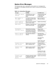
... computer operation. Hard-disk drive failed to failure Data error Decreasing available memory Disk C: failed initialization Diskette drive 0 seek failure Diskette read diskette in diskette drive. Hard-disk drive improperly seated in drive. System Error Messages 3-5 Hard-disk drive damaged. Diskette ...by memory error message). System cannot read the data. Diskette drive interface loose or faulty. Diskette drive faulty. Diskette or hard-disk drive cannot read diskette in diskette drive. System cannot read failure Diskette subsystem reset failed Integrated touch ...
... computer operation. Hard-disk drive failed to failure Data error Decreasing available memory Disk C: failed initialization Diskette drive 0 seek failure Diskette read diskette in diskette drive. Hard-disk drive improperly seated in drive. System Error Messages 3-5 Hard-disk drive damaged. Diskette ...by memory error message). System cannot read the data. Diskette drive interface loose or faulty. Diskette drive faulty. Diskette or hard-disk drive cannot read diskette in diskette drive. System cannot read failure Diskette subsystem reset failed Integrated touch ...

Service Manual
Page 32
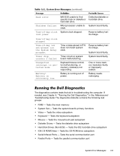
... Card. Diskette writeprotected. Amount of memory recorded in NVRAM does not match memory installed in the diskette drive. Computer cannot enable protective mode. One or more memory modules faulty or improperly seated. Hard-disk drive faulty. 3-6 Dell Latitude CP and CPi Service Manual The diskette may be completed. One or more memory modules faulty or improperly...
... Card. Diskette writeprotected. Amount of memory recorded in NVRAM does not match memory installed in the diskette drive. Computer cannot enable protective mode. One or more memory modules faulty or improperly seated. Hard-disk drive faulty. 3-6 Dell Latitude CP and CPi Service Manual The diskette may be completed. One or more memory modules faulty or improperly...

Service Manual
Page 34
.../read failure at address, read value expecting value No boot device available No boot sector on diskette or hard-disk drive. 3-8 Dell Latitude CP and CPi Service Manual System board faulty. Bad sector or corrupted FAT on hard-disk drive No timer tick interrupt Non-system disk or disk error Not a boot diskette Optional ROM bad checksum...
.../read failure at address, read value expecting value No boot device available No boot sector on diskette or hard-disk drive. 3-8 Dell Latitude CP and CPi Service Manual System board faulty. Bad sector or corrupted FAT on hard-disk drive No timer tick interrupt Non-system disk or disk error Not a boot diskette Optional ROM bad checksum...
Service Manual
Page 35
... malfunctioning, or memory module(s) not responding. One or more memory module(s) faulty or improperly seated. Tests the diskette drive subsystem Hard-Disk Drives (Non-SCSI) - Tests the serial communication port Parallel Ports - Battery is critically low. Tests the main memory System ... Reference and Troubleshooting Guide. Tests the CD-ROM drive subsystem Serial/Infrared Ports - If needed, see Chapter 4, "Running the Dell Diagnostics," in troubleshooting the computer. reset. Tests the video subsystem Keyboard - hard-disk drive. Reserve battery lost power MS-DOS unable to ...
... malfunctioning, or memory module(s) not responding. One or more memory module(s) faulty or improperly seated. Tests the diskette drive subsystem Hard-Disk Drives (Non-SCSI) - Tests the serial communication port Parallel Ports - Battery is critically low. Tests the main memory System ... Reference and Troubleshooting Guide. Tests the CD-ROM drive subsystem Serial/Infrared Ports - If needed, see Chapter 4, "Running the Dell Diagnostics," in troubleshooting the computer. reset. Tests the video subsystem Keyboard - hard-disk drive. Reserve battery lost power MS-DOS unable to ...
Service Manual
Page 43
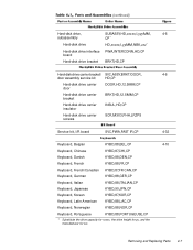
Hard-disk drive, subassembly Hard-disk drive Hard-disk drive interface board Hard-disk drive bracket SUBASSY,HD,xxxxx,I,yyyMM, CP* HD,xxxxx,I,yyMM,NBK,zzz* PWA,INTERCONN,HD,CP BRKT,HD,CP Hard-disk drive carrier bracket/ SVC,ASSY,BRKT/DOOR, door assembly service kit HD,CP Hard-disk drive carrier door DOOR,HD,12.5MM,CP Hard-disk drive carrier bracket BRKT,HD,12.5MM,CP Hard-disk drive carrier insulator...
Hard-disk drive, subassembly Hard-disk drive Hard-disk drive interface board Hard-disk drive bracket SUBASSY,HD,xxxxx,I,yyyMM, CP* HD,xxxxx,I,yyMM,NBK,zzz* PWA,INTERCONN,HD,CP BRKT,HD,CP Hard-disk drive carrier bracket/ SVC,ASSY,BRKT/DOOR, door assembly service kit HD,CP Hard-disk drive carrier door DOOR,HD,12.5MM,CP Hard-disk drive carrier bracket BRKT,HD,12.5MM,CP Hard-disk drive carrier insulator...

Service Manual
Page 48
...ZPS LCD hinge LCD inverter board LCD bezel and latch, 12.1-inch display Keyboard Thermal cooling assembly Touch-pad Palmrest, front edge Palmrest, hard-disk drive area I/R board Upper EMI shield, 1st PC/Video board Back cover Audio board Upper EMI shield, 2nd Bottom-case bracket Exhaust fan ... assembly with system board and processor module ASSY,PRM/PWA,ENGINE, CPxxx* * Substitute the drive capacity for xxxxx, the drive height for yy, and the manufacturer for zzz. 4-18, 4-19 4-16 4-21 4-17 4-9 4-30 4-13 4-12 4-12 4-32 4-11 4-26 4-27 4-31 4-30 4-12 Dell Latitude CP and CPi Service Manual
...ZPS LCD hinge LCD inverter board LCD bezel and latch, 12.1-inch display Keyboard Thermal cooling assembly Touch-pad Palmrest, front edge Palmrest, hard-disk drive area I/R board Upper EMI shield, 1st PC/Video board Back cover Audio board Upper EMI shield, 2nd Bottom-case bracket Exhaust fan ... assembly with system board and processor module ASSY,PRM/PWA,ENGINE, CPxxx* * Substitute the drive capacity for xxxxx, the drive height for yy, and the manufacturer for zzz. 4-18, 4-19 4-16 4-21 4-17 4-9 4-30 4-13 4-12 4-12 4-32 4-11 4-26 4-27 4-31 4-30 4-12 Dell Latitude CP and CPi Service Manual
Service Manual
Page 51
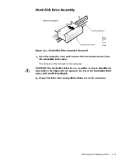
bottom of computer 5-mm screws (2) hard-disk drive door The drive is on the left side of the computer. Removing and Replacing Parts 4-15
bottom of computer 5-mm screws (2) hard-disk drive door The drive is on the left side of the computer. Removing and Replacing Parts 4-15
Service Manual
Page 57
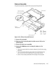
palmrest assembly 5-mm screws (2) 5-mm screw bottom case assembly 12-mm screws (3) One 5-mm screw inside the computer, adjacent to the thermal cooling assembly Two 5-mm screws inside the upper edge of the hard-disk drive bay (you must remove the hard-disk drive to access these screws) Three 12-mm screws underneath the front edge of the touch pad and the palmrest. The palmrest assembly consists of the computer Removing and Replacing Parts 4-21
palmrest assembly 5-mm screws (2) 5-mm screw bottom case assembly 12-mm screws (3) One 5-mm screw inside the computer, adjacent to the thermal cooling assembly Two 5-mm screws inside the upper edge of the hard-disk drive bay (you must remove the hard-disk drive to access these screws) Three 12-mm screws underneath the front edge of the touch pad and the palmrest. The palmrest assembly consists of the computer Removing and Replacing Parts 4-21
Service Manual
Page 78
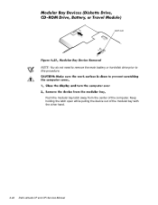
Keep holding the latch open while pulling the device out of the computer. latch lock NOTE: You do not need to remove the main battery or hard-disk drive prior to this procedure. Push the modular bay latch away from the center of the modular bay with the other hand. 4-42 Dell Latitude CP and CPi Service Manual
Keep holding the latch open while pulling the device out of the computer. latch lock NOTE: You do not need to remove the main battery or hard-disk drive prior to this procedure. Push the modular bay latch away from the center of the modular bay with the other hand. 4-42 Dell Latitude CP and CPi Service Manual
Service Manual
Page 88
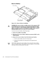
Then position the reserve battery on the hard-disk drive bay so there is minimal slack in the cable. 4-52 Dell Latitude CP and CPi Service Manual Tear the reserve battery free from the system board assembly. b. Remove the remnants of the foam pad from the foam pad. reserve battery reserve battery cable connector (JBAT1) To remove the reserve battery, follow these steps: a. NOTE: When replacing the reserve battery, first connect the reserve battery cable to the system board.
Then position the reserve battery on the hard-disk drive bay so there is minimal slack in the cable. 4-52 Dell Latitude CP and CPi Service Manual Tear the reserve battery free from the system board assembly. b. Remove the remnants of the foam pad from the foam pad. reserve battery reserve battery cable connector (JBAT1) To remove the reserve battery, follow these steps: a. NOTE: When replacing the reserve battery, first connect the reserve battery cable to the system board.
Service Manual
Page 90
..., 4-14 list of, 4-5 hard-disk drive assembly removal, 4-15 help getting, 2-6 I/O panel, 1-3 I/R board removal, 4-51 indicator panel, 1-4 initial procedures system error messages, 3-5 troubleshooting, 2-1 initialization error messages, 3-10 interrupt assignments list of, 1-6 keyboard assembly removal, 4-18 keyboard indicators, 1-5 LCD display hinge removal, 4-38 LCD inverter board removal, 4-35, 4-36 2 Dell Latitude CP and CPi Service Manual...
..., 4-14 list of, 4-5 hard-disk drive assembly removal, 4-15 help getting, 2-6 I/O panel, 1-3 I/R board removal, 4-51 indicator panel, 1-4 initial procedures system error messages, 3-5 troubleshooting, 2-1 initialization error messages, 3-10 interrupt assignments list of, 1-6 keyboard assembly removal, 4-18 keyboard indicators, 1-5 LCD display hinge removal, 4-38 LCD inverter board removal, 4-35, 4-36 2 Dell Latitude CP and CPi Service Manual...


