Service Manual
Page 3
... 1-7 Initial User Contact 2-1 Visual Inspection 2-2 Observing the Boot Routine 2-4 Eliminating Resource Conflicts 2-6 Getting Help 2-6 POST Error Codes 3-1 Battery Failure Codes 3-4 System Error Messages 3-5 Running the Dell Diagnostics 3-9 Recommended Tools 4-2 Precautionary Measures 4-2 Screw Identification and Tightening 4-3 ZIF Connectors 4-4 Field-Replaceable...
... 1-7 Initial User Contact 2-1 Visual Inspection 2-2 Observing the Boot Routine 2-4 Eliminating Resource Conflicts 2-6 Getting Help 2-6 POST Error Codes 3-1 Battery Failure Codes 3-4 System Error Messages 3-5 Running the Dell Diagnostics 3-9 Recommended Tools 4-2 Precautionary Measures 4-2 Screw Identification and Tightening 4-3 ZIF Connectors 4-4 Field-Replaceable...
Service Manual
Page 5
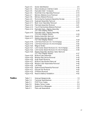
... 4-30. Figure 4-33. Table 3-3. Figure 4-7. Figure 4-10. Figure 4-20. Figure 4-24. Table 3-1. Interrupt Assignments 1-6 Technical Specifications 1-7 POST Error Codes 3-2 Battery Failure Codes 3-4 System Error Messages 3-5 Parts and Assemblies 4-5 vii Figure 4-18. Table 3-2. Figure 4-3. Figure 4-4. Figure 4-26. Figure 4-6. Figure 4-9. Figure 4-23. Figure 4-29. Figure 4-21. Figure 4-14. Figure 4-28. Figure 4-16. Figure...
... 4-30. Figure 4-33. Table 3-3. Figure 4-7. Figure 4-10. Figure 4-20. Figure 4-24. Table 3-1. Interrupt Assignments 1-6 Technical Specifications 1-7 POST Error Codes 3-2 Battery Failure Codes 3-4 System Error Messages 3-5 Parts and Assemblies 4-5 vii Figure 4-18. Table 3-2. Figure 4-3. Figure 4-4. Figure 4-26. Figure 4-6. Figure 4-9. Figure 4-23. Figure 4-29. Figure 4-21. Figure 4-14. Figure 4-28. Figure 4-16. Figure...
Service Manual
Page 22
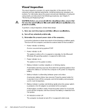
... a visual inspection, follow these steps: Look at the indicators to determine which of the following procedures, see Chapter 4, "Removing and Replacing Parts." Battery indicator is connected to -disk mode. 2-2 Dell Latitude CP and CPi Service Manual Then turn off the computer, and take the actions listed for 4 seconds to room temperature. Power indicator is...
... a visual inspection, follow these steps: Look at the indicators to determine which of the following procedures, see Chapter 4, "Removing and Replacing Parts." Battery indicator is connected to -disk mode. 2-2 Dell Latitude CP and CPi Service Manual Then turn off the computer, and take the actions listed for 4 seconds to room temperature. Power indicator is...
Service Manual
Page 36
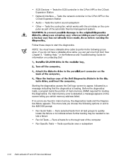
...cable, you choose the following procedure. See Chapter 5, "Getting Help," in sound subsystem Other - Tests a particular area or subsystem 3-10 Dell Latitude CP and CPi Service Manual Tests the SCSI controller in the C/Port APR or the C/Dock Expansion Station Audio - SCSI Devices - Tests the ... Follow these steps to appear, followed by a message indicating that the diagnostics is detected, a message appears on the computer as part of the computer Run Specific Tests - If no errors are found in main memory, the diagnostics loads and the Diagnostics Menu appears....
...cable, you choose the following procedure. See Chapter 5, "Getting Help," in sound subsystem Other - Tests a particular area or subsystem 3-10 Dell Latitude CP and CPi Service Manual Tests the SCSI controller in the C/Port APR or the C/Dock Expansion Station Audio - SCSI Devices - Tests the ... Follow these steps to appear, followed by a message indicating that the diagnostics is detected, a message appears on the computer as part of the computer Run Specific Tests - If no errors are found in main memory, the diagnostics loads and the Diagnostics Menu appears....
Service Manual
Page 37
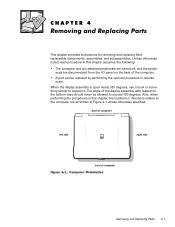
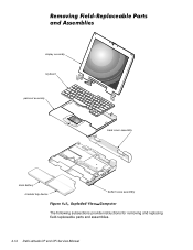
This chapter provides instructions for removing and replacing fieldreplaceable components, assemblies, and subassemblies. A part can be allowed to exceed 180 degrees. back of computer left side right side front of the display assembly with respect to the...be replaced by performing the removal procedure in this chapter, the locations or directions relative to support it. The angle of computer Removing and Replacing Parts 4-1 Also, when performing the procedures in this chapter assumes the following: The computer and any attached peripherals are turned off, and the peripherals ...
This chapter provides instructions for removing and replacing fieldreplaceable components, assemblies, and subassemblies. A part can be allowed to exceed 180 degrees. back of computer left side right side front of the display assembly with respect to the...be replaced by performing the removal procedure in this chapter, the locations or directions relative to support it. The angle of computer Removing and Replacing Parts 4-1 Also, when performing the procedures in this chapter assumes the following: The computer and any attached peripherals are turned off, and the peripherals ...

Service Manual
Page 39
A graphic for correct length. Removing and Replacing Parts 4-3 Match the actual screw to the graphic in the illustration to check for that length screw is also included in the following removal procedures provide the correct screw length as part of the screw's label. Then slide the battery out of the computer. battery bay latch battery The illustrations in the illustration. Slide the battery bay latch away from the center of the battery bay (see Figure 4-2).
A graphic for correct length. Removing and Replacing Parts 4-3 Match the actual screw to the graphic in the illustration to check for that length screw is also included in the following removal procedures provide the correct screw length as part of the screw's label. Then slide the battery out of the computer. battery bay latch battery The illustrations in the illustration. Slide the battery bay latch away from the center of the battery bay (see Figure 4-2).

Service Manual
Page 40
movable part of connector (do not remove) Some of the computer's interface connectors are not removable, but they must be released to disconnect a cable from them To disconnect an interface cable from a ZIF connector, follow these steps: To reconnect an interface cable to a ZIF connector, follow these steps: To ensure a firm connection, make sure the ZIF connector is completely closed. 4-4 Dell Latitude CP and CPi Service Manual These connectors are zero insertion force (ZIF) connectors.
movable part of connector (do not remove) Some of the computer's interface connectors are not removable, but they must be released to disconnect a cable from them To disconnect an interface cable from a ZIF connector, follow these steps: To reconnect an interface cable to a ZIF connector, follow these steps: To ensure a firm connection, make sure the ZIF connector is completely closed. 4-4 Dell Latitude CP and CPi Service Manual These connectors are zero insertion force (ZIF) connectors.
Service Manual
Page 41
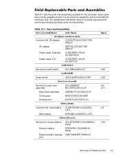
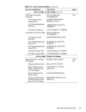
Table 4-1 lists the parts and assemblies available for reference only. CUS,ADPT,AC,EXT,20V,70W, NBK,CP ADPT,AC,EXT,20V,70W, NBK,CP CORD,PWR,110V,6F, AC ADPT,AUS CORD,PWR,110V,6F, AC ADPT,US Service kit, audio board SVC,PWA,AUDIO,CP 4-25 Audio shield SHLD,W/SPR,...,RSRV,7.2V,30MAH,6, 4-32 NIHD Reserve battery BTRY,RSRV,7.2V,30MAH,6, NIHD Reserve battery sponge PAD,FOAM,BRTY,RSRV,CP pad Removing and Replacing Parts 4-5 Some parts may only be available as part of a service kit or assembly, and are provided for the computer. The subsections that follow Table 4-1 provide instructions...
Table 4-1 lists the parts and assemblies available for reference only. CUS,ADPT,AC,EXT,20V,70W, NBK,CP ADPT,AC,EXT,20V,70W, NBK,CP CORD,PWR,110V,6F, AC ADPT,AUS CORD,PWR,110V,6F, AC ADPT,US Service kit, audio board SVC,PWA,AUDIO,CP 4-25 Audio shield SHLD,W/SPR,...,RSRV,7.2V,30MAH,6, 4-32 NIHD Reserve battery BTRY,RSRV,7.2V,30MAH,6, NIHD Reserve battery sponge PAD,FOAM,BRTY,RSRV,CP pad Removing and Replacing Parts 4-5 Some parts may only be available as part of a service kit or assembly, and are provided for the computer. The subsections that follow Table 4-1 provide instructions...
Service Manual
Page 43
... KYBD,88,ITALIAN,CP Keyboard, Japanese KYBD,90,JPN,CP Keyboard, Korean KYBD,87,KOR,CP Keyboard, Latin American KYBD,88,LAC,CP Keyboard, Norwegian KYBD,88,NOR,CP Keyboard, Portuguese KYBD,88,PORTUGEUSE,CP * Substitute the drive capacity for xxxxx, the drive height for yy, and the manufacturer for zzz. 4-6 4-6 4-32 4-10 Removing and Replacing Parts 4-7
... KYBD,88,ITALIAN,CP Keyboard, Japanese KYBD,90,JPN,CP Keyboard, Korean KYBD,87,KOR,CP Keyboard, Latin American KYBD,88,LAC,CP Keyboard, Norwegian KYBD,88,NOR,CP Keyboard, Portuguese KYBD,88,PORTUGEUSE,CP * Substitute the drive capacity for xxxxx, the drive height for yy, and the manufacturer for zzz. 4-6 4-6 4-32 4-10 Removing and Replacing Parts 4-7
Service Manual
Page 45
... LCD/Cable service kit, Sharp SVC,LCD/CBL/INV, TFT,SHARP,CP LCD inverter board assembly ASSY,PWA,INVRTR,LCD,CP LCD cable subassembly, SUBASSY,CBL/HLDR,TFT, Sharp (TFT) SHARP,CP LCD cable subassembly, SUBASSY,CBL/HLDR,STN, Sharp (STN) SHARP,CP LCD panel, Sharp (TFT) LCD,TFT,SVGA,12.1", SHARP LCD panel... CVR,SCR,LCD,13.3",TOP, OVAL,CPX CVR,SCR,BTM,RND,ADH BMPR,RBR,UPR,LCD,13.3", NBK,CPX 4-18 4-15, 4-17 Removing and Replacing Parts 4-9
... LCD/Cable service kit, Sharp SVC,LCD/CBL/INV, TFT,SHARP,CP LCD inverter board assembly ASSY,PWA,INVRTR,LCD,CP LCD cable subassembly, SUBASSY,CBL/HLDR,TFT, Sharp (TFT) SHARP,CP LCD cable subassembly, SUBASSY,CBL/HLDR,STN, Sharp (STN) SHARP,CP LCD panel, Sharp (TFT) LCD,TFT,SVGA,12.1", SHARP LCD panel... CVR,SCR,LCD,13.3",TOP, OVAL,CPX CVR,SCR,BTM,RND,ADH BMPR,RBR,UPR,LCD,13.3", NBK,CPX 4-18 4-15, 4-17 Removing and Replacing Parts 4-9
Service Manual
Page 47
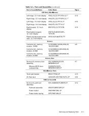
... door subassembly SUBASSY,DOOR, MEM/BIOS,NB,CP Touch-pad bracket Air flow duct BRCKT,TPAD,CP 4-13 GDE,INTK,AIR,FAN,PLSTC,CP 4-30 Service kit, palmrest SVC,SUBASSY,PLMRST,CP 4-12 assembly Palmrest assembly ASSY,PLMRST,GRY,CP Power button SWT,PWR SW, CP Power button spring SPR,PWR SW,CP Removing and Replacing Parts 4-11
... door subassembly SUBASSY,DOOR, MEM/BIOS,NB,CP Touch-pad bracket Air flow duct BRCKT,TPAD,CP 4-13 GDE,INTK,AIR,FAN,PLSTC,CP 4-30 Service kit, palmrest SVC,SUBASSY,PLMRST,CP 4-12 assembly Palmrest assembly ASSY,PLMRST,GRY,CP Power button SWT,PWR SW, CP Power button spring SPR,PWR SW,CP Removing and Replacing Parts 4-11

Service Manual
Page 49
...,PRM/PWA,ENGINE, CPixxx* SUBASSY,PWA/ENGINE,CP PWA,FAST IR,CP GRMT,RBR,BOOT,MCPHN PWA,PLN,0M,NB,CP PWA,DTRBD,VID/PCMCIA,CP PWA,LED,CP SHLD,BTM,PLN ASSY,CP SHLD,TOP,1ST,PLN ASSY,CP SHLD,TOP,2ND,PLN ASSY,CP FAN,25X25X10,CP MCPHN,CP BTRY,RSRV,7.2,30MAH,6,NIHD PAD,FOAM,BTRY,RSRV...,CP Service kit, thermal cooling SVC,SUBASSY,HTSNK, 4-30 subassembly CPU,HYB,CP Touch-pad service kit SVC,TPAD,SQ,INTFC,CP Touch-pad subassembly TPA,INTFC,CP * Substitute the drive capacity for xxxxx, the drive height for yy, and the manufacturer for zzz. 4-13 Removing and Replacing Parts 4-13
...,PRM/PWA,ENGINE, CPixxx* SUBASSY,PWA/ENGINE,CP PWA,FAST IR,CP GRMT,RBR,BOOT,MCPHN PWA,PLN,0M,NB,CP PWA,DTRBD,VID/PCMCIA,CP PWA,LED,CP SHLD,BTM,PLN ASSY,CP SHLD,TOP,1ST,PLN ASSY,CP SHLD,TOP,2ND,PLN ASSY,CP FAN,25X25X10,CP MCPHN,CP BTRY,RSRV,7.2,30MAH,6,NIHD PAD,FOAM,BTRY,RSRV...,CP Service kit, thermal cooling SVC,SUBASSY,HTSNK, 4-30 subassembly CPU,HYB,CP Touch-pad service kit SVC,TPAD,SQ,INTFC,CP Touch-pad subassembly TPA,INTFC,CP * Substitute the drive capacity for xxxxx, the drive height for yy, and the manufacturer for zzz. 4-13 Removing and Replacing Parts 4-13
Service Manual
Page 50
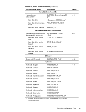
display assembly keyboard palmrest assembly back cover assembly main battery modular bay device bottom case assembly The following subsections provide instructions for removing and replacing field-replaceable parts and assemblies. 4-14 Dell Latitude CP and CPi Service Manual
display assembly keyboard palmrest assembly back cover assembly main battery modular bay device bottom case assembly The following subsections provide instructions for removing and replacing field-replaceable parts and assemblies. 4-14 Dell Latitude CP and CPi Service Manual
Service Manual
Page 51
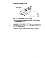
bottom of computer 5-mm screws (2) hard-disk drive door The drive is on the left side of the computer. Removing and Replacing Parts 4-15
bottom of computer 5-mm screws (2) hard-disk drive door The drive is on the left side of the computer. Removing and Replacing Parts 4-15
Service Manual
Page 53
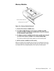
Align the notch near the center of its retaining clips. Removing and Replacing Parts 4-17 memory module sockets (2) retaining clips (2 per socket) The memory module should rotate upward out of the memory module with the corresponding key in the memory module socket. Memory modules can be installed only one way. Do not attempt to force the memory module into the socket.
Align the notch near the center of its retaining clips. Removing and Replacing Parts 4-17 memory module sockets (2) retaining clips (2 per socket) The memory module should rotate upward out of the memory module with the corresponding key in the memory module socket. Memory modules can be installed only one way. Do not attempt to force the memory module into the socket.
Service Manual
Page 55
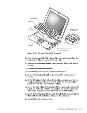
metal tabs (2) keyboard plastic tabs (2) palmrest scalloped edge of blank key deflect palmrest outward to release keyboard Follow these steps when replacing the keyboard assembly: Removing and Replacing Parts 4-19
metal tabs (2) keyboard plastic tabs (2) palmrest scalloped edge of blank key deflect palmrest outward to release keyboard Follow these steps when replacing the keyboard assembly: Removing and Replacing Parts 4-19
Service Manual
Page 57
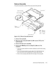
palmrest assembly 5-mm screws (2) 5-mm screw bottom case assembly 12-mm screws (3) One 5-mm screw inside the computer, adjacent to the thermal cooling assembly Two 5-mm screws inside the upper edge of the hard-disk drive bay (you must remove the hard-disk drive to access these screws) Three 12-mm screws underneath the front edge of the touch pad and the palmrest. The palmrest assembly consists of the computer Removing and Replacing Parts 4-21
palmrest assembly 5-mm screws (2) 5-mm screw bottom case assembly 12-mm screws (3) One 5-mm screw inside the computer, adjacent to the thermal cooling assembly Two 5-mm screws inside the upper edge of the hard-disk drive bay (you must remove the hard-disk drive to access these screws) Three 12-mm screws underneath the front edge of the touch pad and the palmrest. The palmrest assembly consists of the computer Removing and Replacing Parts 4-21
Service Manual
Page 59
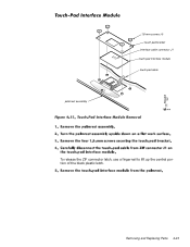
palmrest assembly 1.8-mm screws (4) touch-pad bracket interface cable connector J1 touch-pad interface module touch-pad cable To release the ZIF connector latch, use a fingernail to lift up the central portion of the black plastic latch. Removing and Replacing Parts 4-23
palmrest assembly 1.8-mm screws (4) touch-pad bracket interface cable connector J1 touch-pad interface module touch-pad cable To release the ZIF connector latch, use a fingernail to lift up the central portion of the black plastic latch. Removing and Replacing Parts 4-23
Service Manual
Page 61
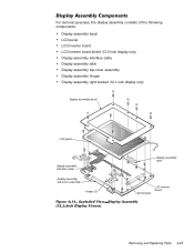
For removal purposes, the display assembly consists of the following components: Display assembly bezel LCD panel LCD inverter board LCD inverter board shield (13.3-inch display only) Display-assembly interface cable Display assembly latch Display assembly top-cover assembly Display assembly hinges Display assembly right bracket (12.1-inch display only) display assembly bezel LCD panel display-assembly interface cable display-assembly top-cover assembly hinges (2) display assembly latch LCD inverter board right bracket Removing and Replacing Parts 4-25
For removal purposes, the display assembly consists of the following components: Display assembly bezel LCD panel LCD inverter board LCD inverter board shield (13.3-inch display only) Display-assembly interface cable Display assembly latch Display assembly top-cover assembly Display assembly hinges Display assembly right bracket (12.1-inch display only) display assembly bezel LCD panel display-assembly interface cable display-assembly top-cover assembly hinges (2) display assembly latch LCD inverter board right bracket Removing and Replacing Parts 4-25
Service Manual
Page 63
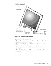
Removing and Replacing Parts 4-27 display assembly display-assembly interface-cable grounding screws (2) display-assembly interface cable 5-mm screws (4) hinges (2) Grasp the grounding tabs and pull the connector straight up from the system board.
Removing and Replacing Parts 4-27 display assembly display-assembly interface-cable grounding screws (2) display-assembly interface cable 5-mm screws (4) hinges (2) Grasp the grounding tabs and pull the connector straight up from the system board.


