Service Manual
Page 5
...Specifications 1-7 POST Error Codes 3-2 Battery Failure Codes 3-4 System Error Messages 3-5 Parts and Assemblies 4-5 vii Figure 4-6. Figure 4-18. Figure 4-32. Figure 4-7. Figure 4-19. Figure 4-23. Figure 4-12. Figure 4-5. Figure 4-16. Table 3-3. Table 4-1. Figure 4-28. Screw Identification 4-3 Disconnecting an Interface Cable 4-4 Exploded View-Computer 4-14 Hard-Disk Drive Assembly Removal 4-15 Memory Module Cover Removal 4-16 Memory Module Removal 4-17 Removing the Keyboard Assembly Screws 4-18 Keyboard Assembly Removal 4-19 Back Cover Assembly Removal...
...Specifications 1-7 POST Error Codes 3-2 Battery Failure Codes 3-4 System Error Messages 3-5 Parts and Assemblies 4-5 vii Figure 4-6. Figure 4-18. Figure 4-32. Figure 4-7. Figure 4-19. Figure 4-23. Figure 4-12. Figure 4-5. Figure 4-16. Table 3-3. Table 4-1. Figure 4-28. Screw Identification 4-3 Disconnecting an Interface Cable 4-4 Exploded View-Computer 4-14 Hard-Disk Drive Assembly Removal 4-15 Memory Module Cover Removal 4-16 Memory Module Removal 4-17 Removing the Keyboard Assembly Screws 4-18 Keyboard Assembly Removal 4-19 Back Cover Assembly Removal...
Service Manual
Page 7
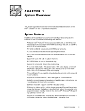
... mode [or standby mode for a battery in the upper PC Card connector. Software wavetable support and SRS 3-D audio control. Support for the Microsoft® Windows® 98 operating system] or turned off). Support for a hard-disk drive in the modular bay. System Overview 1-1 Support for a zoom video PC Card in the modular bay. A Sound Blaster Pro-compatible integrated audio controller with the computer's main battery, a second battery doubles battery operating time. When used with voice and music functions. A CD-ROM drive...
... mode [or standby mode for a battery in the upper PC Card connector. Software wavetable support and SRS 3-D audio control. Support for the Microsoft® Windows® 98 operating system] or turned off). Support for a hard-disk drive in the modular bay. System Overview 1-1 Support for a zoom video PC Card in the modular bay. A Sound Blaster Pro-compatible integrated audio controller with the computer's main battery, a second battery doubles battery operating time. When used with voice and music functions. A CD-ROM drive...
Service Manual
Page 8
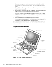
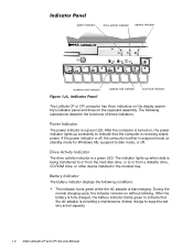
... or starts a small fan when necessary. For a complete list of system features, see "Technical Specifications" found later in flash memory and that help you conserve battery power. Two power management modessuspend mode (or standby mode in Windows 98) and suspend-to-disk modethat can be upgraded by diskette if required. display microphone power button keyboard touch pad battery bay touch pad buttons (2) modular bay display latch indicator panel cooling-fan air intake AC adapter connector audio jacks (3) speakers (2) 1-2 Dell Latitude CP and CPi Service Manual
... or starts a small fan when necessary. For a complete list of system features, see "Technical Specifications" found later in flash memory and that help you conserve battery power. Two power management modessuspend mode (or standby mode in Windows 98) and suspend-to-disk modethat can be upgraded by diskette if required. display microphone power button keyboard touch pad battery bay touch pad buttons (2) modular bay display latch indicator panel cooling-fan air intake AC adapter connector audio jacks (3) speakers (2) 1-2 Dell Latitude CP and CPi Service Manual
Service Manual
Page 10
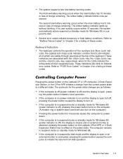
... AC adapter is providing a maintenance (trickle) charge to or from the hard-disk drive, or to keep the battery at full capacity. 1-4 Dell Latitude CP and CPi Service Manual If the power indicator is off . The battery indicator displays the following subsections describe the functions of these indicators. After the battery is fully charged, the battery indicator blinks green to -disk mode, or off , the computer is being transferred to or from a diskette drive, CD-ROM drive, or other device installed...
... AC adapter is providing a maintenance (trickle) charge to or from the hard-disk drive, or to keep the battery at full capacity. 1-4 Dell Latitude CP and CPi Service Manual If the power indicator is off . The battery indicator displays the following subsections describe the functions of these indicators. After the battery is fully charged, the battery indicator blinks green to -disk mode, or off , the computer is being transferred to or from a diskette drive, CD-ROM drive, or other device installed...
Service Manual
Page 11
...-from the current power state to turn on . System Overview 1-5 The amber battery indicator blinks once per second. If no user activity occurs within 15 seconds, the system automatically enters suspend (or standby mode for 4 seconds causes the computer to -disk mode and the display is open, pressing the power button initiates a boot operation. The keyboard controls the operation of the numbers lock (Num Lock) indicator, the capitals lock (Caps Lock) indicator, and the Scroll Lock indicator, all of which...
...-from the current power state to turn on . System Overview 1-5 The amber battery indicator blinks once per second. If no user activity occurs within 15 seconds, the system automatically enters suspend (or standby mode for 4 seconds causes the computer to -disk mode and the display is open, pressing the power button initiates a boot operation. The keyboard controls the operation of the numbers lock (Num Lock) indicator, the capitals lock (Caps Lock) indicator, and the Scroll Lock indicator, all of which...
Service Manual
Page 12
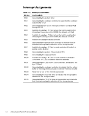
... bay to indicate that the drive requires the attention of the integrated touch pad or external PS/2 mouse is full Reserved for use by a PC Card Generated by the USB and PC Card controllers; available for use by a PC Card or audio controller unless the C/Port APR or C/Dock Expansion Station is attached Generated by the keyboard controller to indicate that the output buffer of the microprocessor 1-6 Dell Latitude CP and CPi Service Manual
... bay to indicate that the drive requires the attention of the integrated touch pad or external PS/2 mouse is full Reserved for use by a PC Card Generated by the USB and PC Card controllers; available for use by a PC Card or audio controller unless the C/Port APR or C/Dock Expansion Station is attached Generated by the keyboard controller to indicate that the output buffer of the microprocessor 1-6 Dell Latitude CP and CPi Service Manual
Service Manual
Page 14
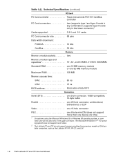
...-byte buffer Parallel one device at a time) 1 On systems using the Microsoft Windows 95 or Windows 98 operating system, a zoom video card can be used only in any combination; The Microsoft Windows NT ® 4.0 operating system does not support zoom video. 2 The Latitude CP and CPi do not support memory modules from previous models of Dell portable computers, such as the Latitude XP, XPi, XPi CD, and LM. 1-8 Dell Latitude CP and CPi Service Manual
...-byte buffer Parallel one device at a time) 1 On systems using the Microsoft Windows 95 or Windows 98 operating system, a zoom video card can be used only in any combination; The Microsoft Windows NT ® 4.0 operating system does not support zoom video. 2 The Latitude CP and CPi do not support memory modules from previous models of Dell portable computers, such as the Latitude XP, XPi, XPi CD, and LM. 1-8 Dell Latitude CP and CPi Service Manual
Service Manual
Page 16
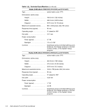
... (10.64 inches) Diagonal 337.8 mm (13.3 inches) Maximum resolution/colors 1024 x 768 pixels; 262,144 colors Response time (typical 50 ms Operating angle 0° (closed) to 180° Dot pitch 0.26 mm Power consumption: Panel (typical 1.7 W Backlight 2.6 W Controls brightness can be controlled with key combinations, the Display window in the Dell Control Center, or the System Setup program 1-10 Dell Latitude CP and CPi Service Manual
... (10.64 inches) Diagonal 337.8 mm (13.3 inches) Maximum resolution/colors 1024 x 768 pixels; 262,144 colors Response time (typical 50 ms Operating angle 0° (closed) to 180° Dot pitch 0.26 mm Power consumption: Panel (typical 1.7 W Backlight 2.6 W Controls brightness can be controlled with key combinations, the Display window in the Dell Control Center, or the System Setup program 1-10 Dell Latitude CP and CPi Service Manual
Service Manual
Page 21
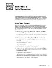
... correct starting point for a description of the correct procedure. Can the user duplicate the problem? When you perform these steps: See "Maintaining Your Computer" in the proper procedure, or direct him or her to the appropriate user documentation for troubleshooting the computer. Instruct the user in the online Dell Latitude CP and CPi User's Guide. These procedures can often indicate the cause of user error...
... correct starting point for a description of the correct procedure. Can the user duplicate the problem? When you perform these steps: See "Maintaining Your Computer" in the proper procedure, or direct him or her to the appropriate user documentation for troubleshooting the computer. Instruct the user in the online Dell Latitude CP and CPi User's Guide. These procedures can often indicate the cause of user error...
Service Manual
Page 22
... -disk mode. 2-2 Dell Latitude CP and CPi Service Manual An error occurred during system POST. then replace the battery or connect the computer to AC power to -disk mode. The system is in suspend (or standby, for that condition: Power indicator is either off or in suspend-to room temperature. Battery indicator is connected to determine which of the following procedures, see Chapter 4, "Removing and Replacing Parts." Shut down the operating system; A fatal battery...
... -disk mode. 2-2 Dell Latitude CP and CPi Service Manual An error occurred during system POST. then replace the battery or connect the computer to AC power to -disk mode. The system is in suspend (or standby, for that condition: Power indicator is either off or in suspend-to room temperature. Battery indicator is connected to determine which of the following procedures, see Chapter 4, "Removing and Replacing Parts." Shut down the operating system; A fatal battery...
Service Manual
Page 24
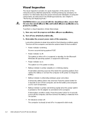
... that users make copies of obvious physical damage. The monitor and its cable are secure enough to ensure a firm connection. The attached device and its interface cable are set according to the instructions in Chapter 4 of obvious physical damage. Yes. The monitor's controls are free of the Dell Latitude CP Reference and Troubleshooting Guide. 2-4 Dell Latitude CP and CPi Service Manual For instructions, see "Before You Start Testing" in the documentation for any indications of...
... that users make copies of obvious physical damage. The monitor and its cable are secure enough to ensure a firm connection. The attached device and its interface cable are set according to the instructions in Chapter 4 of obvious physical damage. Yes. The monitor's controls are free of the Dell Latitude CP Reference and Troubleshooting Guide. 2-4 Dell Latitude CP and CPi Service Manual For instructions, see "Before You Start Testing" in the documentation for any indications of...
Service Manual
Page 31
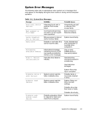
... diskette drive. System board faulty. Diskette or hard-disk drive cannot read failure Diskette subsystem reset failed Integrated touch pad or external PS/2 mouse failed. System Error Messages 3-5 Bad command or filename entered. Diskette faulty or incorrectly inserted in pathname specified. Diskette subsystem failed to respond to initialize. The following table lists (in modular bay. Auxiliary device failure Bad command or File Name Cache disabled...
... diskette drive. System board faulty. Diskette or hard-disk drive cannot read failure Diskette subsystem reset failed Integrated touch pad or external PS/2 mouse failed. System Error Messages 3-5 Bad command or filename entered. Diskette faulty or incorrectly inserted in pathname specified. Diskette subsystem failed to respond to initialize. The following table lists (in modular bay. Auxiliary device failure Bad command or File Name Cache disabled...

Service Manual
Page 32
..., improperly seated, or improperly configured. Computer cannot enable protective mode. Message indicates system failure. The CD-ROM drive does not respond to commands from the computer. System board faulty. Computer cannot identify PC Card. Hard-disk drive faulty. 3-6 Dell Latitude CP and CPi Service Manual Defective or unformatted diskette. Amount of memory recorded in NVRAM does not match memory installed in the diskette drive. Hard-disk drive not responding to commands from computer...
..., improperly seated, or improperly configured. Computer cannot enable protective mode. Message indicates system failure. The CD-ROM drive does not respond to commands from the computer. System board faulty. Computer cannot identify PC Card. Hard-disk drive faulty. 3-6 Dell Latitude CP and CPi Service Manual Defective or unformatted diskette. Amount of memory recorded in NVRAM does not match memory installed in the diskette drive. Hard-disk drive not responding to commands from computer...
Service Manual
Page 33
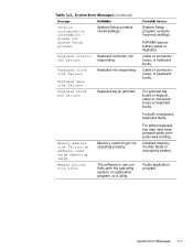
... software in keyboard, keyboard faulty. System Setup program contains incorrect settings. Cable or connector loose, or keyboard faulty. System Error Messages 3-7 Keyboard control- Keyboard controller not ler failure responding. Installed memory module faulty or improperly seated. For built-in use conflicts with the operating system, an application program, or a utility. For external keyboard or keypad, cable or connector loose or keyboard faulty. Keyboard key(s) jammed. For either keyboard, key may have been pressed while computer was booting...
... software in keyboard, keyboard faulty. System Setup program contains incorrect settings. Cable or connector loose, or keyboard faulty. System Error Messages 3-7 Keyboard control- Keyboard controller not ler failure responding. Installed memory module faulty or improperly seated. For built-in use conflicts with the operating system, an application program, or a utility. For external keyboard or keypad, cable or connector loose or keyboard faulty. Keyboard key(s) jammed. For either keyboard, key may have been pressed while computer was booting...

Service Manual
Page 34
... sector or corrupted FAT on harddisk drive. No boot sector on diskette or hard-disk drive. 3-8 Dell Latitude CP and CPi Service Manual Timer on hard-disk drive or diskette. ROM in external device faulty. No operating system files on system board malfunctioning. Unable to locate a sector on diskette or hard-disk drive. System board faulty. MS-DOS® unable to boot from which it is trying to boot. Memory data line failure at address, read...
... sector or corrupted FAT on harddisk drive. No boot sector on diskette or hard-disk drive. 3-8 Dell Latitude CP and CPi Service Manual Timer on hard-disk drive or diskette. ROM in external device faulty. No operating system files on system board malfunctioning. Unable to locate a sector on diskette or hard-disk drive. System board faulty. MS-DOS® unable to boot from which it is trying to boot. Memory data line failure at address, read...
Service Manual
Page 36
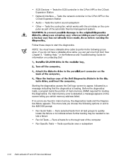
SCSI Devices - Tests the SCSI controller in the C/Port APR or the C/Dock Expansion Station Audio - Tests the network controller in the C/Port APR or the C/Dock Expansion Station Network Interface - NOTE: You must have a diskette-drive cable, you choose the following procedure. Starting the diagnostics causes the Dell logo screen to perform the following options or exit to the MS-DOS prompt: Run Quick Tests...
SCSI Devices - Tests the SCSI controller in the C/Port APR or the C/Dock Expansion Station Audio - Tests the network controller in the C/Port APR or the C/Dock Expansion Station Network Interface - NOTE: You must have a diskette-drive cable, you choose the following procedure. Starting the diagnostics causes the Dell logo screen to perform the following options or exit to the MS-DOS prompt: Run Quick Tests...
Service Manual
Page 90
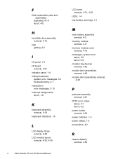
...4-18 keyboard indicators, 1-5 LCD display hinge removal, 4-38 LCD inverter board removal, 4-35, 4-36 2 Dell Latitude CP and CPi Service Manual LCD panel removal, 4-31, 4-32 LEDs, 1-4 low-battery warnings, 1-4 main battery assembly removal, 4-3 memory module removal, 4-17 memory module cover removal, 4-16 messages, system error about, 3-5 list of, 3-5 modular bay devices removal, 4-42 module latch assemblies removal, 4-46 module latch assemblies removal, 4-46 palmrest assembly removal, 4-21 POST error codes about, 3-1 list of, 3-2 power button removal, 4-24 power indicator, 1-4 power states...
...4-18 keyboard indicators, 1-5 LCD display hinge removal, 4-38 LCD inverter board removal, 4-35, 4-36 2 Dell Latitude CP and CPi Service Manual LCD panel removal, 4-31, 4-32 LEDs, 1-4 low-battery warnings, 1-4 main battery assembly removal, 4-3 memory module removal, 4-17 memory module cover removal, 4-16 messages, system error about, 3-5 list of, 3-5 modular bay devices removal, 4-42 module latch assemblies removal, 4-46 module latch assemblies removal, 4-46 palmrest assembly removal, 4-21 POST error codes about, 3-1 list of, 3-2 power button removal, 4-24 power indicator, 1-4 power states...
Setup Guide
Page 3
.... Follow the instructions on for the first time. 1. Remove any PC Card installed in the PC Card slot of the operating system for use with your computer uses Windows 95, the computer is completed and you want to use with the Dell Latitude C/Dock Expansion Station or C/Port Advanced Port Replicator (APR). Dell Latitude CP Before You Turn On Your Computer 1-1 For details on completing the setup of the computer...
.... Follow the instructions on for the first time. 1. Remove any PC Card installed in the PC Card slot of the operating system for use with your computer uses Windows 95, the computer is completed and you want to use with the Dell Latitude C/Dock Expansion Station or C/Port Advanced Port Replicator (APR). Dell Latitude CP Before You Turn On Your Computer 1-1 For details on completing the setup of the computer...
Setup Guide
Page 4
... the Dell Latitude C/Dock Expansion Station Windows NT 4.0 IDE Driver diskette into the computer's diskette drive. 7. To determine the PCI bus speed of the computer, see "Setting Up a Hardware Profile" in the C/Dock media bay. Follow the instructions on the computer undocked, and complete the operating system setup. Create a hardware profile for maximum performance as follows: 1. Click the Start button, point to restart the computer, remove...
... the Dell Latitude C/Dock Expansion Station Windows NT 4.0 IDE Driver diskette into the computer's diskette drive. 7. To determine the PCI bus speed of the computer, see "Setting Up a Hardware Profile" in the C/Dock media bay. Follow the instructions on the computer undocked, and complete the operating system setup. Create a hardware profile for maximum performance as follows: 1. Click the Start button, point to restart the computer, remove...
Setup Guide
Page 5
... OEM Option window, highlight 3Com Fast EtherLink XL Adapter (3C905) and click OK. 16. Click Change. 6. Use the Boot Controller tab to Settings, and click Control Panel. 3. SCSI Controller Driver If your network administrator before beginning this procedure came with the C/Dock Expansion Station. 9. The diskettes you are using a C/Port APR, go to install the driver for a PCI Video Card" in a specific DMA channel. Undock the computer. 2. Click the Start button, point...
... OEM Option window, highlight 3Com Fast EtherLink XL Adapter (3C905) and click OK. 16. Click Change. 6. Use the Boot Controller tab to Settings, and click Control Panel. 3. SCSI Controller Driver If your network administrator before beginning this procedure came with the C/Dock Expansion Station. 9. The diskettes you are using a C/Port APR, go to install the driver for a PCI Video Card" in a specific DMA channel. Undock the computer. 2. Click the Start button, point...


